Originally Posted by
RCISFUN
I entered the same numbers you used and came up with the same results, however I still have a question, see photo.
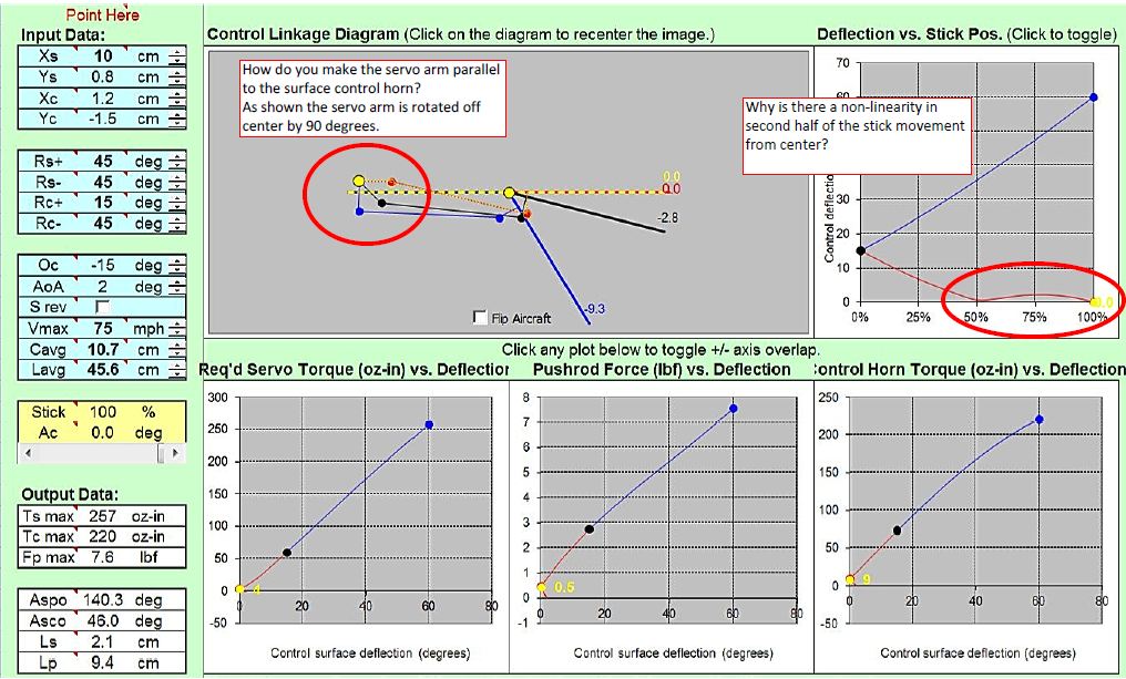
In the cad drawing I have the servo arm drawn as I though it should be which is different than the diagram in the simulation.
It's got a weird result because some of your figures are not right, you have not matched the centre of servo travel to the centre of flap travel. Total flap travel is 60 degrees but you have defined its centre at 15 degrees which is 1/4 rather than 1/2 travel, so the program has had to work out how to make the flap travel 15 degrees one way with 1/2 servo rotation whilst making it travel 45 degrees with 1/2 servo rotation in the other direction. In reality you don't do that mechanically, which is what the program has calculated, you do it electronically in your Tx servo settings, e.g off-setting the centre value.
Since flap travel is 60 degres, half flap (which will equat to servo centre) is 30, so in the Oc box put in -30, not -15. Then your Rc+ and Rc- both should be +30, i.e. 30 degrees either side of a -30 centre value (the Oc value). Now you will get a proper diagram showing a sensible servo output arm, and sensible torque graphs.
At first, when you put the Tx switch to the mid position the flap will go to about 30 degrees down. Simply adjust the Tx flap control/servo centre point until you get the required travel.