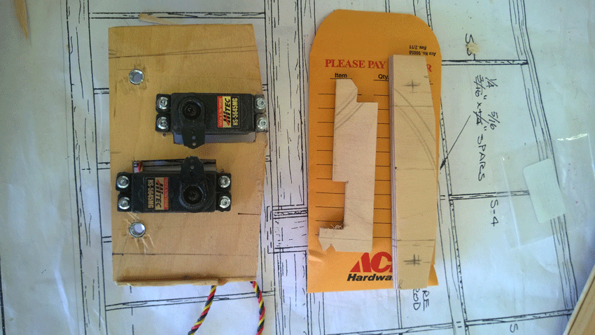
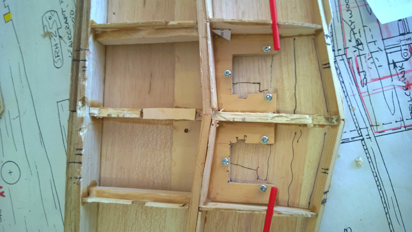
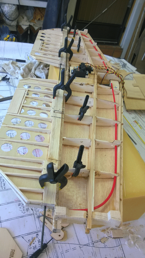
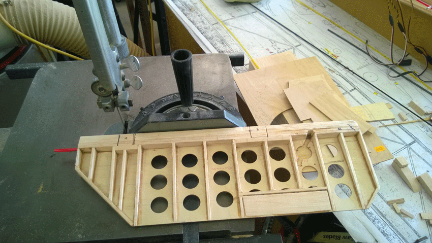
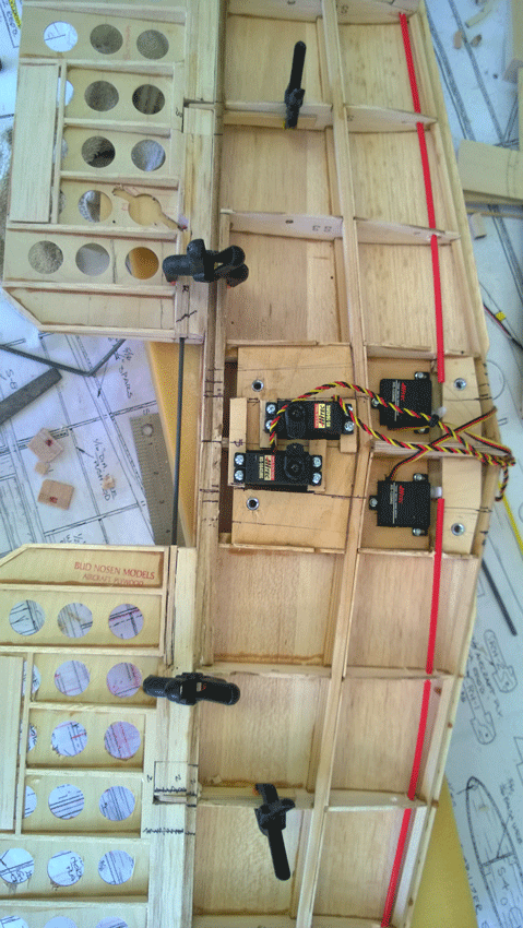
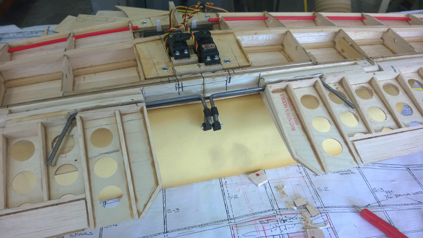

It is my decision to mount all servos in the stab, this requires that the whole stab be removable to get to the servos and linkage for maintenance and or repairs/adjustment. Photo 1 shows the ply plates and hold down member for the front plate. This hold down hooks under the front spruce LE as well as under the spruce main spar so as to ensure that the front hold down plate does not come loose. Photo 2 just shows the location for the hold down plates. I decided not to shape the LE of the elevator right now so it could be clamped to the stab for marking, cutting and gluing. Used square on the band saw to keep cuts for the tabs nice, clean and square. I used a 1/8" CF rod for the hinge as it fits perfectly in the Nyrod tube and the weight is way down over metal. The lite ply hinge points were recut from 1/8" aviation ply and drilled out for the CF rod, they were also extended for additional gluing area to the stab rib. By keeping the elevator so it can be clamped I could then run the CF rod through the entire tail section to ensure all the hinge areas are perfectly aligned when they are glued up - this system has appeared to work very well.
Rudder linkage runs through the stab and out the back and will be covered at the exit point as per scale. Each of the servos applies 90 # of torque so should be plenty for each rudder. I did reposition the Nyrod once the servos were in place, however, it appears that the servos may need to be moved back about 1/16" to give some additional clearance for the linkage.
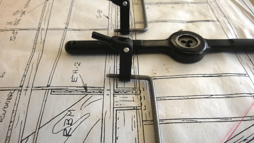
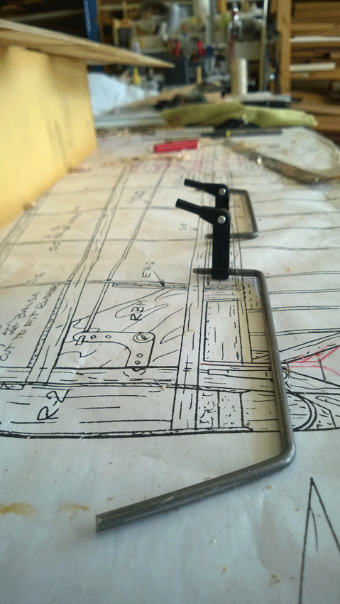
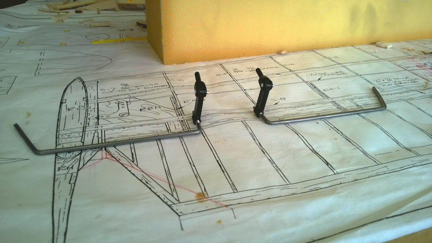
Once the elevator tabs were glued to the stab with the CF rod in place the elevator the elevators were cut and the Nyrod tube removed to install the elevator metal linkage rod. This spring steel rod was bent and threads created with a die to match the nylon adjustable linkage. Cutting in the threads was much more of a task than I anticipated as the rod was slightly large in diameter for the die. Once completed the nylon linkage treaded on just fine. The rod will be sandwiched between 1/8" ply which will use blind nuts to hold rod to the elevator. It appears I will need to cut a small amount of elevator away and re-bend the rod to allow for some additional spacing for the nylon linkage. The rod area will be covered, and screwed in, using 1/16" ply so that the elevator could be removed if required. The 1/16" ply cover plate will have the 1/4" filler glued to it to fill in the area cut out for the rod in the LE of the elevator. Note, that the elevator servos require a reverser Y connection, where the rudder servos do not. I then sanded the elevator LE to shape and obtained the necessary clearance for the degree of elevator rotation as per plan.
Away in the 5th wheel for a family wedding and should be able to get back to building on Thur. or Friday of this next week.