SLOTTED FLAP MOD - Installment 1
http://naca.central.cranfield.ac.uk/...report-664.pdf
Before beginning the mod, we need to take some measurements for our particular wing and do some calculations. No complex formula is involved, just simple arithmetic and geometry. The basis for all these measurements is the chord. Using data presented in TR 664, we can determine values for our new flap chord, our slot lip length, the slot entry radius, flap cove radius, and later on when installing the flap mount, figure dimensions to double-check the correct placement of our flap relative to the aft edge of the slot lip as the flap deploys.
I will be using the ARF from Nitroplanes as the basis for my modification. The primary difference between a SIG kit and the ARF is: 1) the chord for the ARF is 15.0 inches vs. 15.125 for the SIG kit Even so, the calculations should vary only a little.
The main structural differences in the ARF vs. SIG version is that the aft spar further aft, which makes for a narrwower (chordwise) slot lip extension. If you have the original SIG kit , you can either make your slot lip extension longer (chordwise) to capture the SIG aft spar, or you can fab and install your own sub-spar from which to attach your slot extension.
Fortunately, in any case,
The SIG Kadet Senior has a straight wing, therefore a constant chord, and this simplifies everything. The flap will have a constant chord from inboard to outboard.
Our numbers from Figure 5 of TR 664 (Slotted Flap Configuration 2-h):
Reference Values
Chord (C) = 15.0 inches
therefore: C = 15.0 inches
Flap Chord (C[SUB]f[/SUB]) = C X 0.2566
therefore: C[SUB]f[/SUB]= 15.0 X .2566 = 3.849 inches
Slot Lip (E) = C X 0.827
therefore: E =15.0 X 0.827 = 12.40 inches
Slot Entry Radius (R[SUB]e[/SUB]) = C X 0.0789
therefore: R[SUB]e[/SUB] = 15.0 X .0789 = 1.18 inches
Cove Radius (R[SUB]c[/SUB]) = C X .0475 =0.712 inches
therefore: R[SUB]c[/SUB] = 0.712 inches
The graphic from NACA TR 664 Figure 5, gives all the dimensions for configuration 2-h, EXCEPT the flap chord dimension. It is depicted in configuration 2-i, immediately below 2-h.
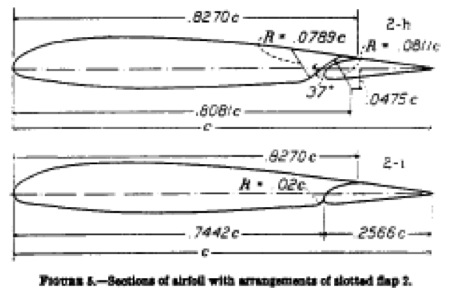
.2566 c gives us a flap 25.66% of the original wing chord. Generous indeed.