
SLOTTED FLAP MOD –cont’d
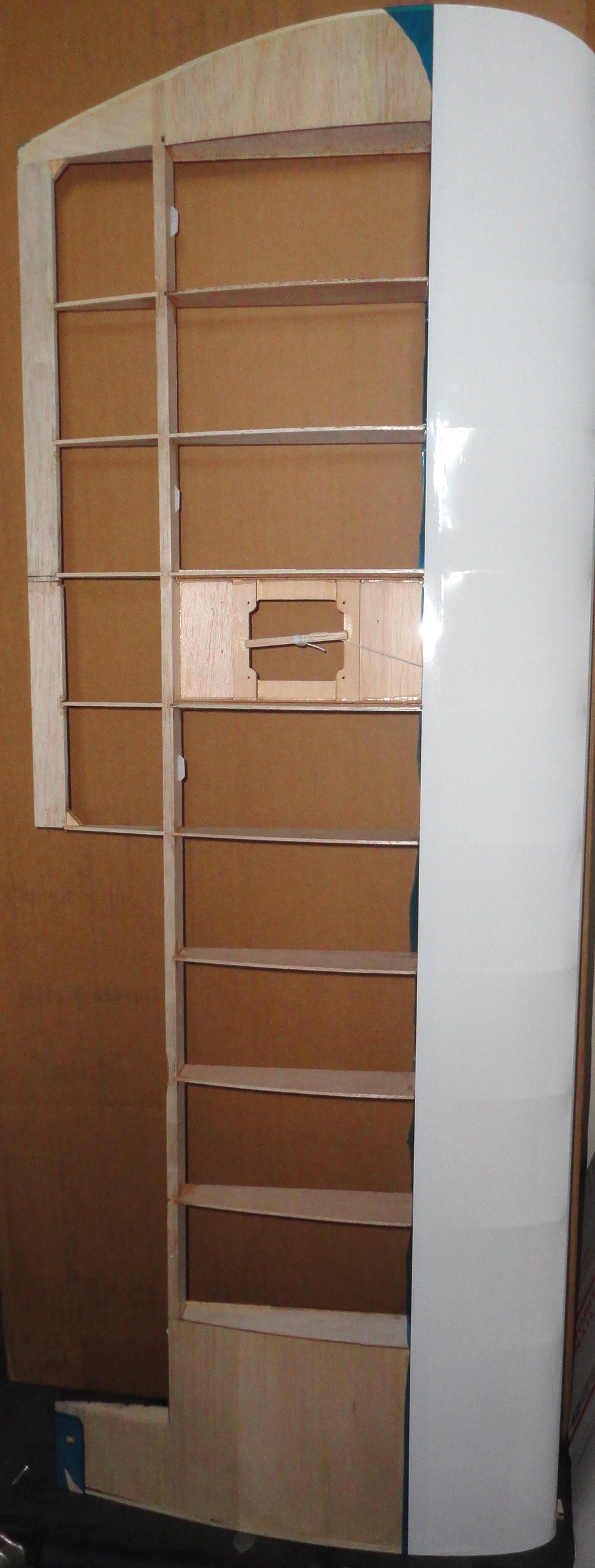
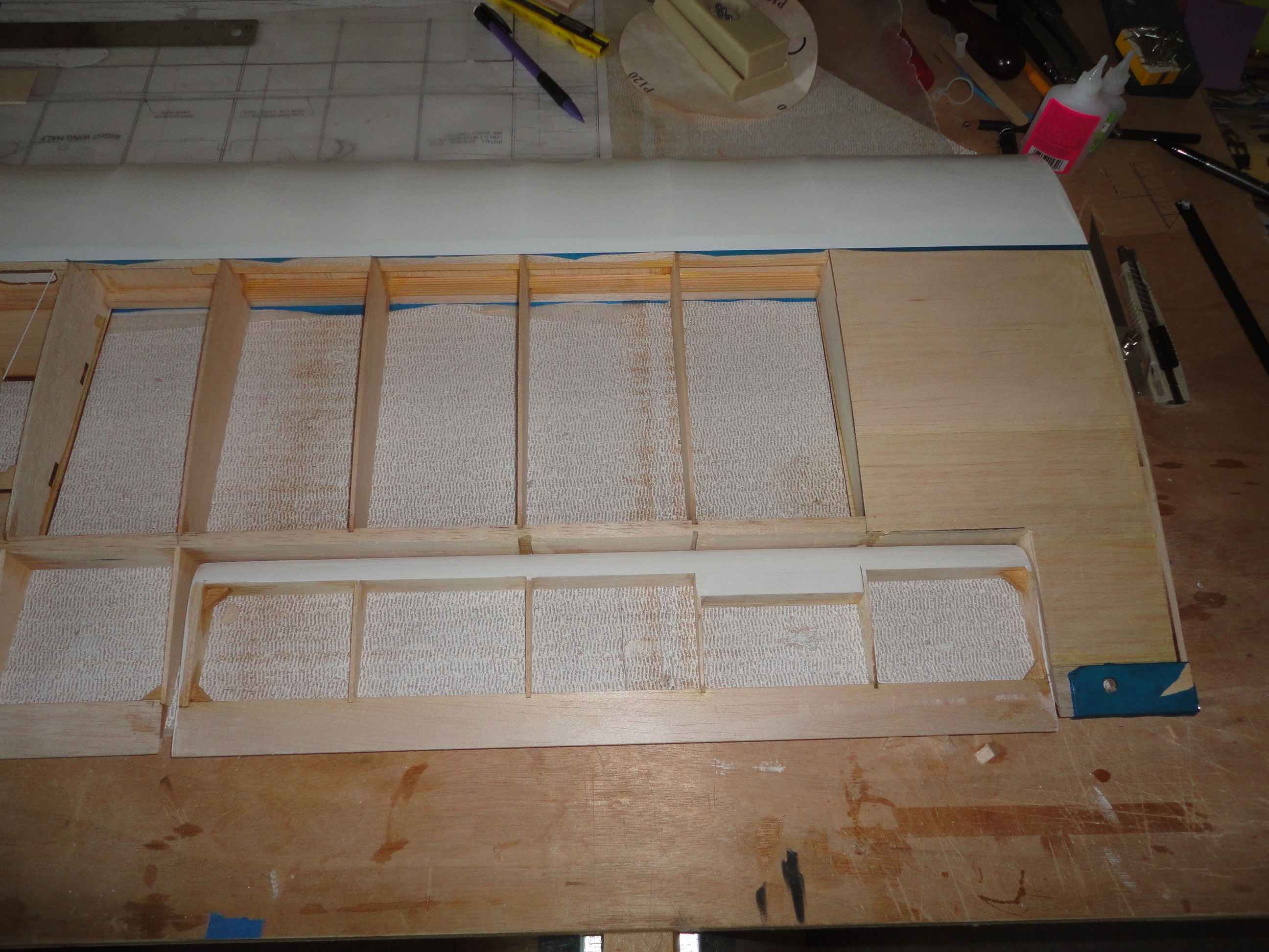
Having cut new rib sections and new rib notches for attachment to the rear spar and trailing edge, the TE was reconstructed. Flap bay is ready for the flap cove mod, while will come soon.
First, the flap.
Carl Wenzinger and team surmised (as I’m sure that we all do,intuitively) that a flap of “good airfoil shape” would provide the greatest effect since the flap is a lifting component as well.
They used a NACA 6318 nose profile.
Since I don’t know what that is, and would rather avoid the tedium of plotting airfoil coordinates, as fun as that may sound, I went by what was depicted in TR 664 and tried my best to replicate that profile. I would imagine that most any flap profile representing a nice fat airfoil with a flat bottom would be effective. Interestingly, the P-3 and C-130 flap profiles are versions a bit squished from this, but seeing as they are Fowler flaps, they need the flatter upper profile, to extend before translating down.
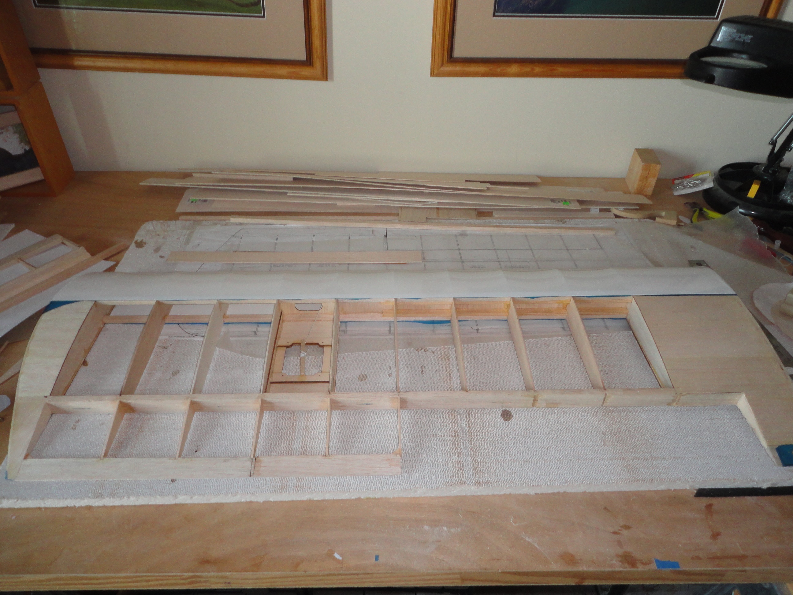
BUILDING THE FLAP PROFILE for the BIG SIG flaps:
The salvaged aileron is the base structure for this flap mod. I created a rib profile template from heavy cardstock. It allowed me to draw/trim the profile to match what I wanted. As you can see from the construction picture, the flap template affixed to the end of the aileron, showed that it was short chord-wise, and a little high “airfoil-wise.” If you do this mod from existing airplanes, you will find that most flap and aileron profiles do not offer the very generous 26% flap chord required for this mod. You have to build them up, and sand ‘em down.
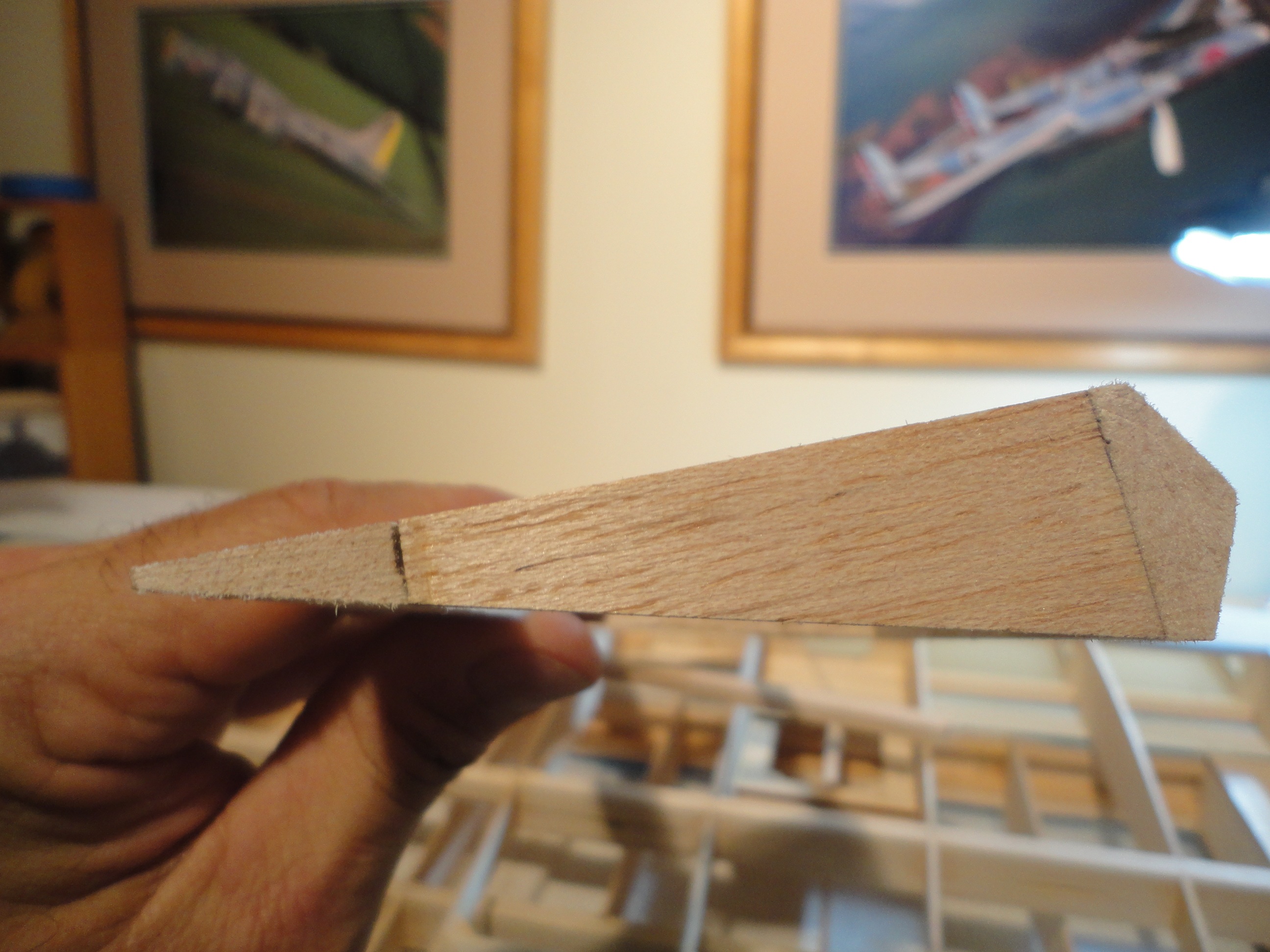
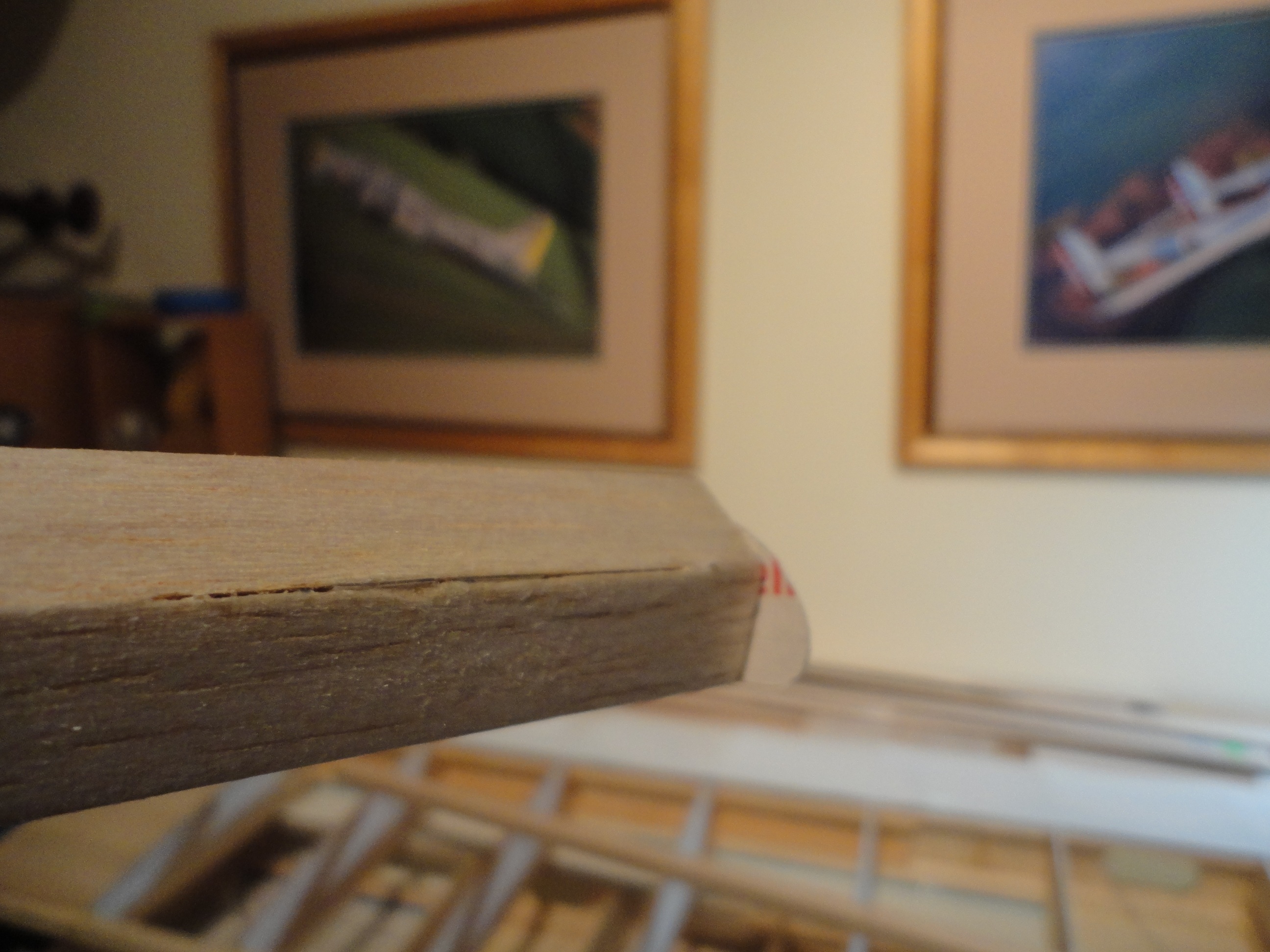
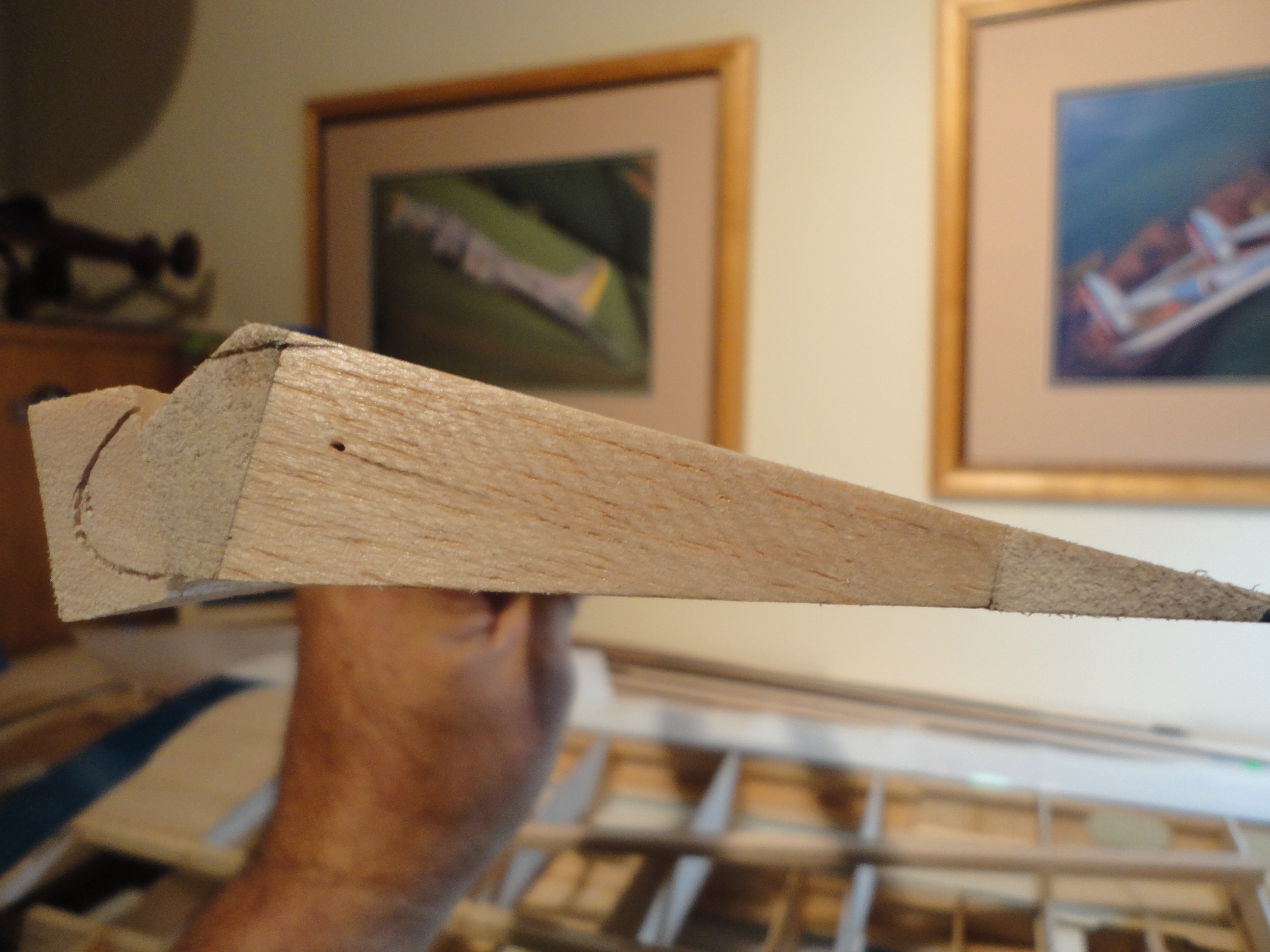
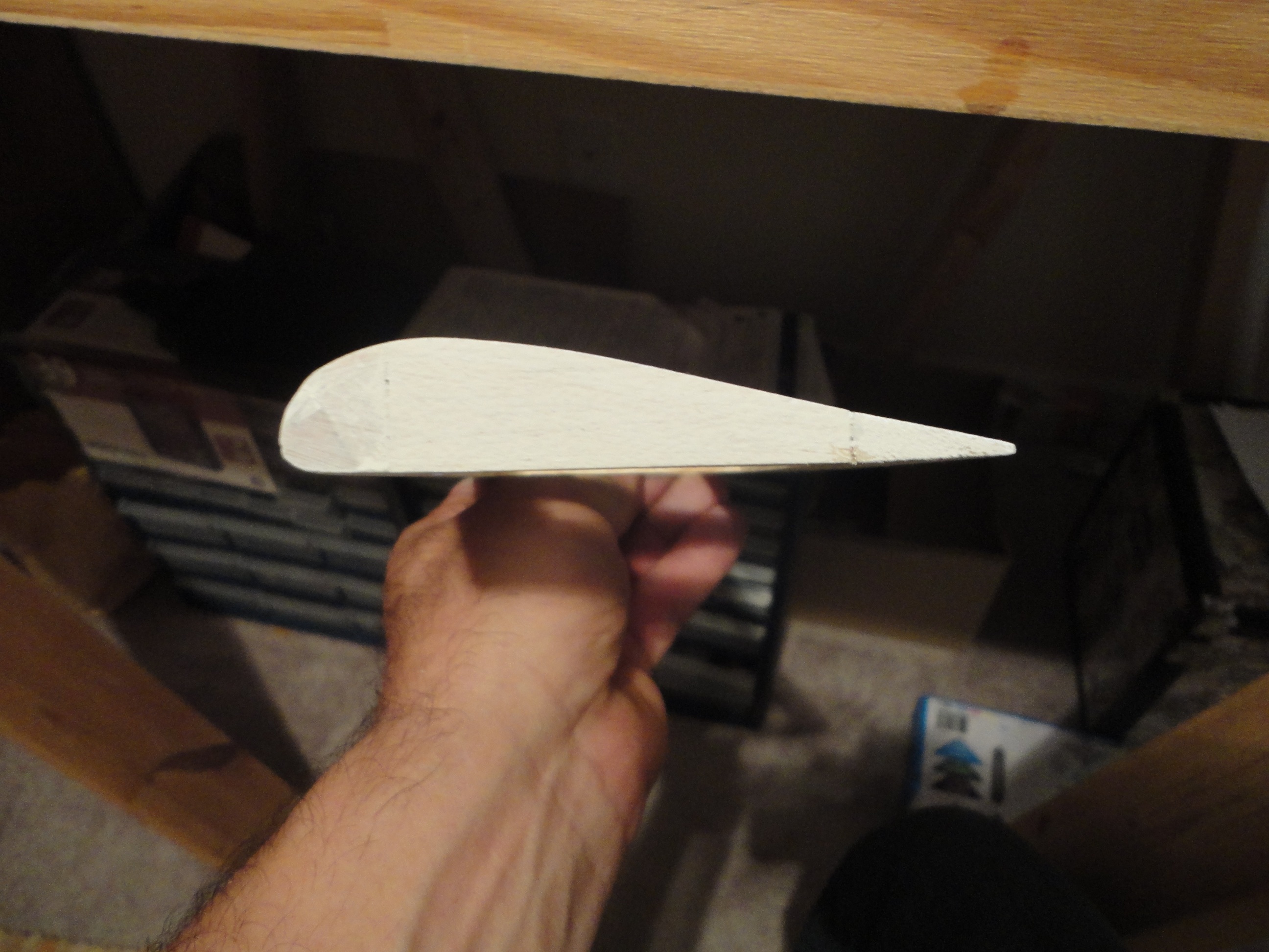
I added balsa to the LE and drew the profile from the template onto the end, giving me my desired profile. Easy enough.
The beveled leading edge of the aileron made it difficult to glue balsa so that there were no complex angles to trim to and deal with. Solution: fill the remaining gap with a sandable material after the profile sanding is completed and final sand to complete the job. Seal with a sandable sealer. I used latex paint. Sands very nicely and leaves a good finish for monokote to adhere to. Probably not a good foundation for oil-based paint.........or is it?
Could someone tell me?
Of note, however is the consideration that the flaps are “faired into the contour of the main airfoil over the rest of [the flap’s] length.” Makes sense.
That is important in this situation because:
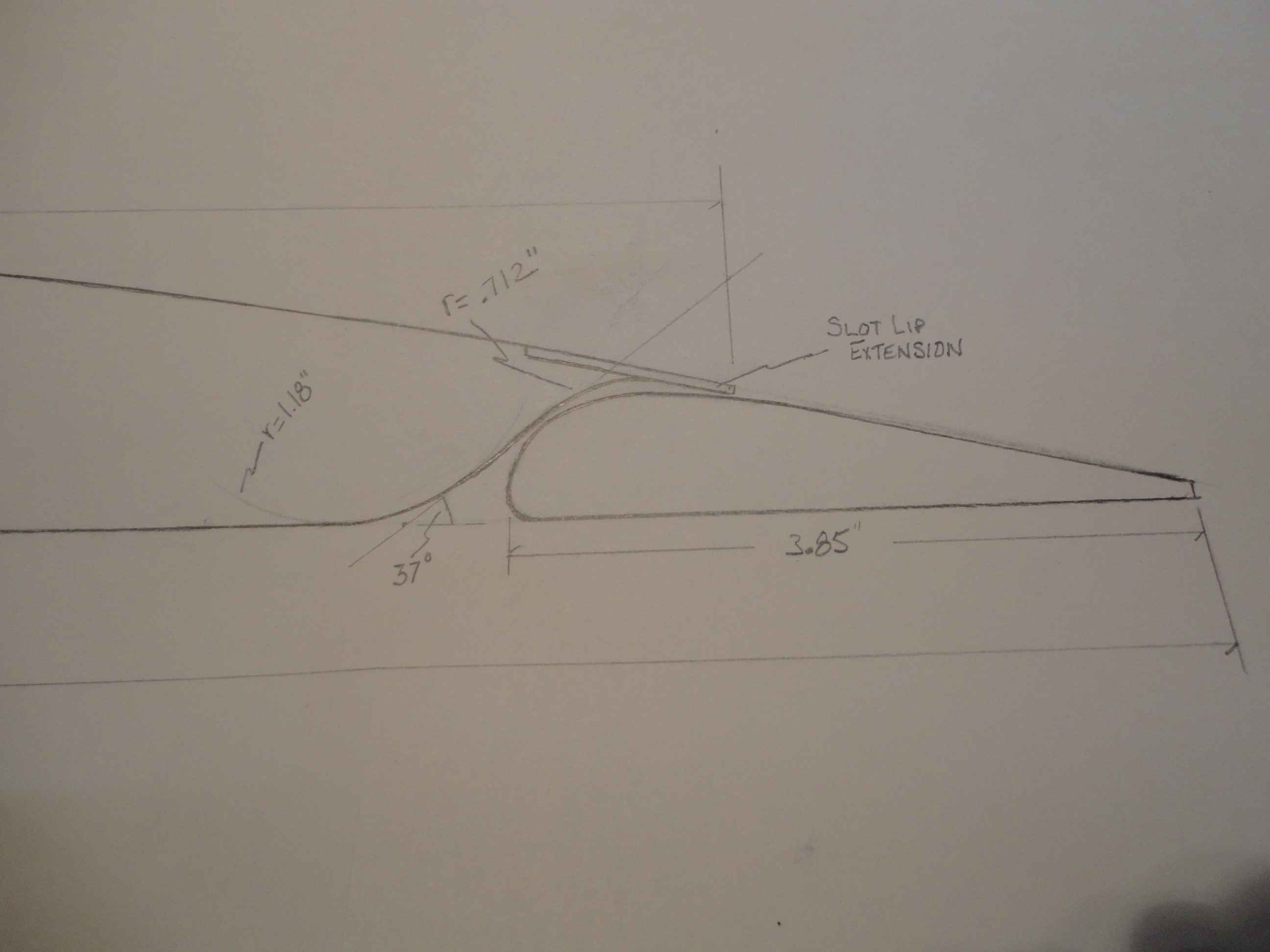
The flap should be rigged so that it seals the aft slot lip/flap interface. This is not a tight fit, mind you (which would lead to servo binding) but should be as close as possible.
Where is that on the flap then?
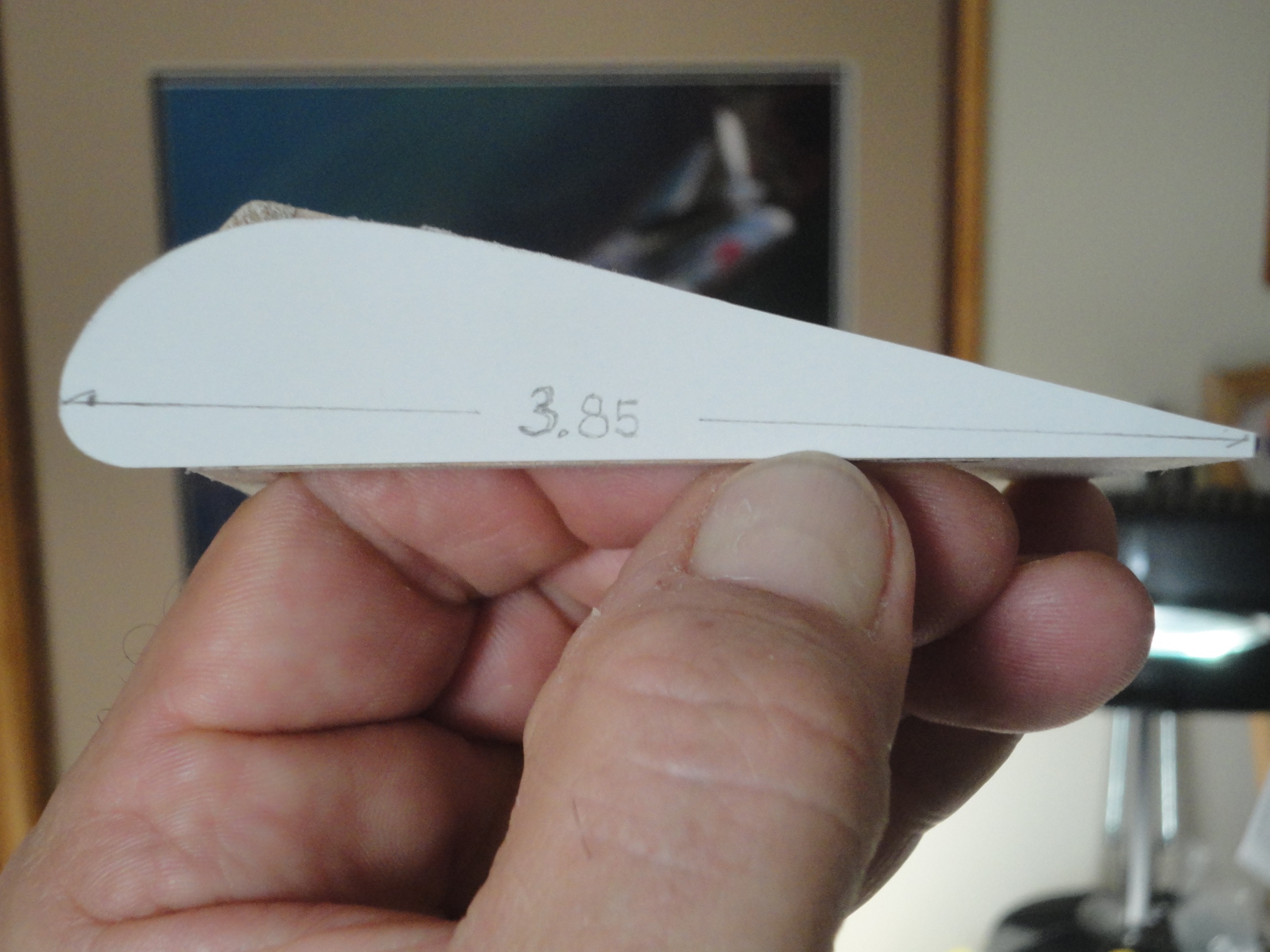
Wing Chord (C) = 15 inches
Slot Lip Extension (E) = 12.40 inches
(C) minus (E) should give me the dimension from the TE where the Slot Lip Extension is located.
15.0 – 12.4 = 2.6 inches from the trailing edge
Therefore, the faired section of the flap begins 2.6 inches from the flap trailing edge. This arithmetic should help alleviate fiddling with the flap contour later, also, the aileron rib profile gives me a strong basis for the flap rib profile , so I will sand the top where needed. The flap can then move out from under the slot lip extension without interfering.
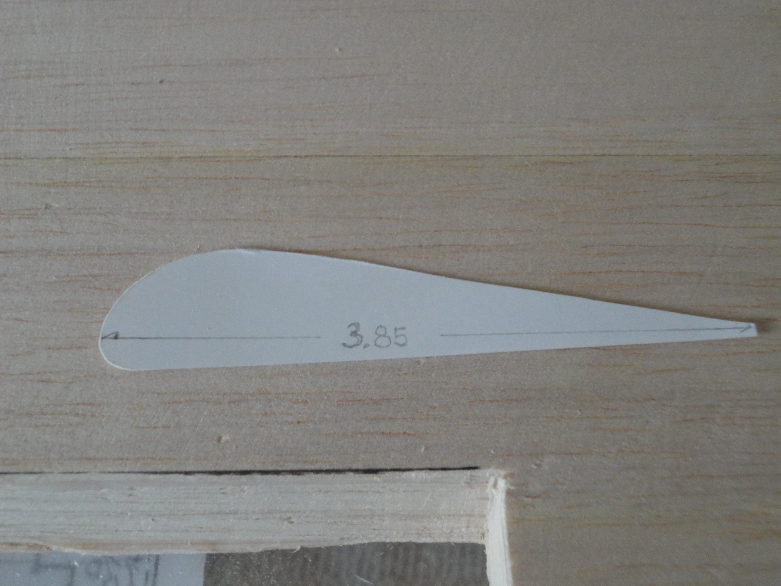
Remember, our flap chord is 3.85 inches so we should have no trouble profiling to the FCS 1.25 (Flap Chord Station 1.25). We’ll see.
I could have built the flap cove first, but from past experience, there are complications associated with this, too numerous to delineate here, so please take my word for it.
The flap will nest in the flap cutout, of course. On my first mod on another plane, instant panic when I placed the flap into the cutout and the trailing edges did not line up.
Huh? I thought.
Ah! When we profile the slot entry transition, the nose of the flap will move forward into the cove and line up with the rest of the trailing edge.
Here is an installation drawing of the arrangement, minus the hinge mounts.
 NEXT UP:
 Flap Cove, Slot Entry Transition, and Slot Lip Extension
Last edited by nealmontgomery; 01-27-2015 at 09:00 AM.