SLOTTED FLAP MOD – cont’d
Apologies for the time lag between posts………SWMBO decreed that a new kitchen backsplash must be installed and the cabinetry repainted. Such has been my recent commitment and reason for the lack of continuity.
We press on with the Senior Kadet Slotted Flap Modification series.
As a former Teacher, I would like to discuss the rationale of the:
Slot Entry, Slot Lip Extension, and Flap Cove
The Slot Entry is the transition into the flap cove from the lower surface of the wing. While there are many profiles of this transition, the most effective transitions producing the highest lift coefficients allow for a smooth airflow into the flap cove and allow a portion of the airflow to travel up and over the flap leading edge where that air is re-combined with airflow off the upper surface of the wing. Flow separation from the flap is delayed, providing lift for a longer period before the drag penalty occurs.
This Slot Entry profile is typically a rather large, smooth radius, as opposed to a sharp corner at the forward lower edge of the flap cove as seen edge-on.
A side profile view provided by flyingagin in post #2435
shows one of many designs for a flap/cove/lip combination. I cannot be at all critical of this design since I configured many of my own earlier flap designs
just as this, or worse, aerodynamically speaking. 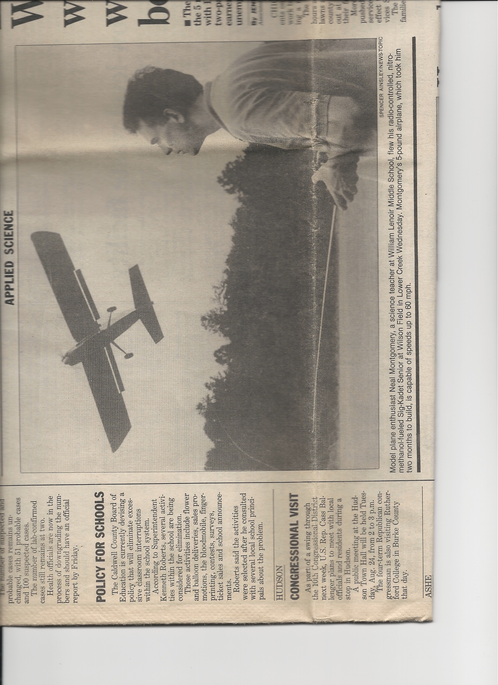 I was in the local papaer many years ago...... Look at these flaps! Hanging' out there, and I thought I was the MAN building those flaps! I suppose they worked..........but just okay!
Anyway...........
My thinking back then was that a gap or a big discontinuity in the undersurface of the wing leading into the flap area would cause undue drag at cruise speeds. After reading the TR664, I came to learn from the research team’s conclusion was that although there is some drag penalty at cruise speeds due to the gap created by the transition into the flap cove, the SR Kadet, or any such slower type models would not suffer greatly from such a discontinuity. Indeed, even when these studies were being conducted at the Langley Research Center, the faster airplanes of the day benefited more from the advantages of the TR 664 flap design at approach and landing speeds than were penalized from the design in normal cruise speed range.
Below are some examples of early-on slotted flap modifications to my Icon A-5 and FMS T-28. i wanted to work on the foamies before grinding on my balsa models. You can see the slot entry areas are not as pronounced as it may seem. These were relatively short-chord wings so the radii of the slot entries were tightly rounded.
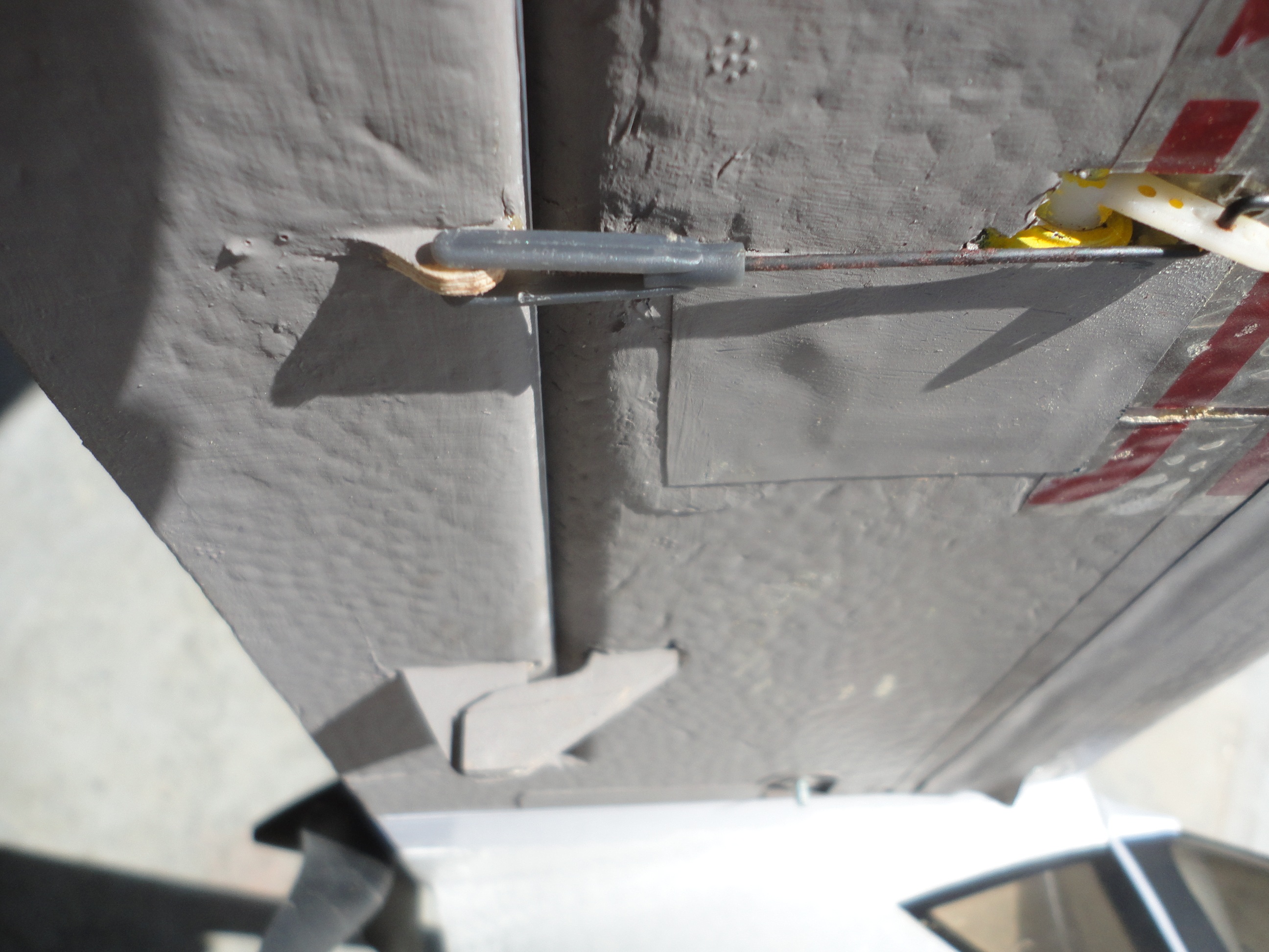
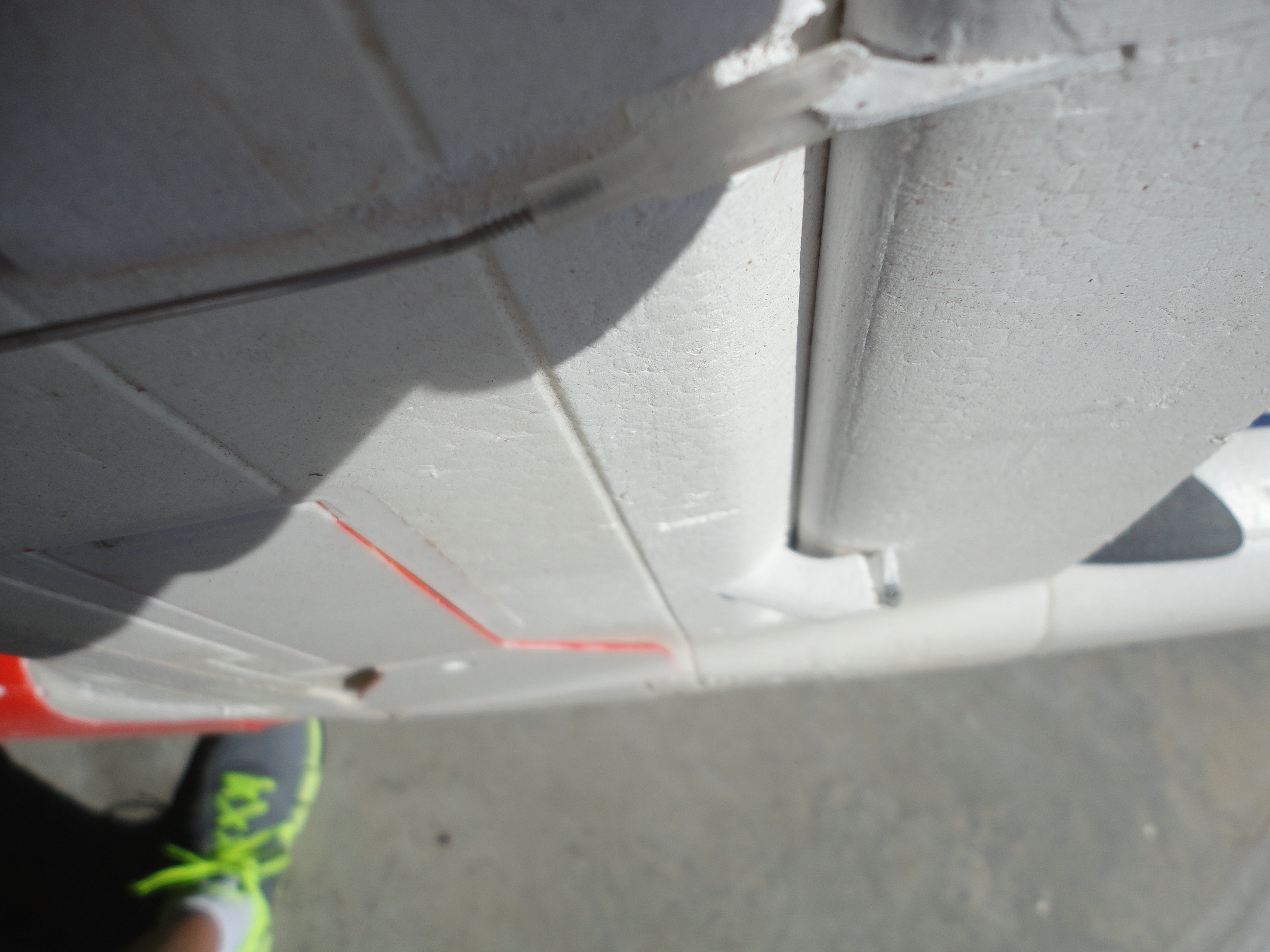
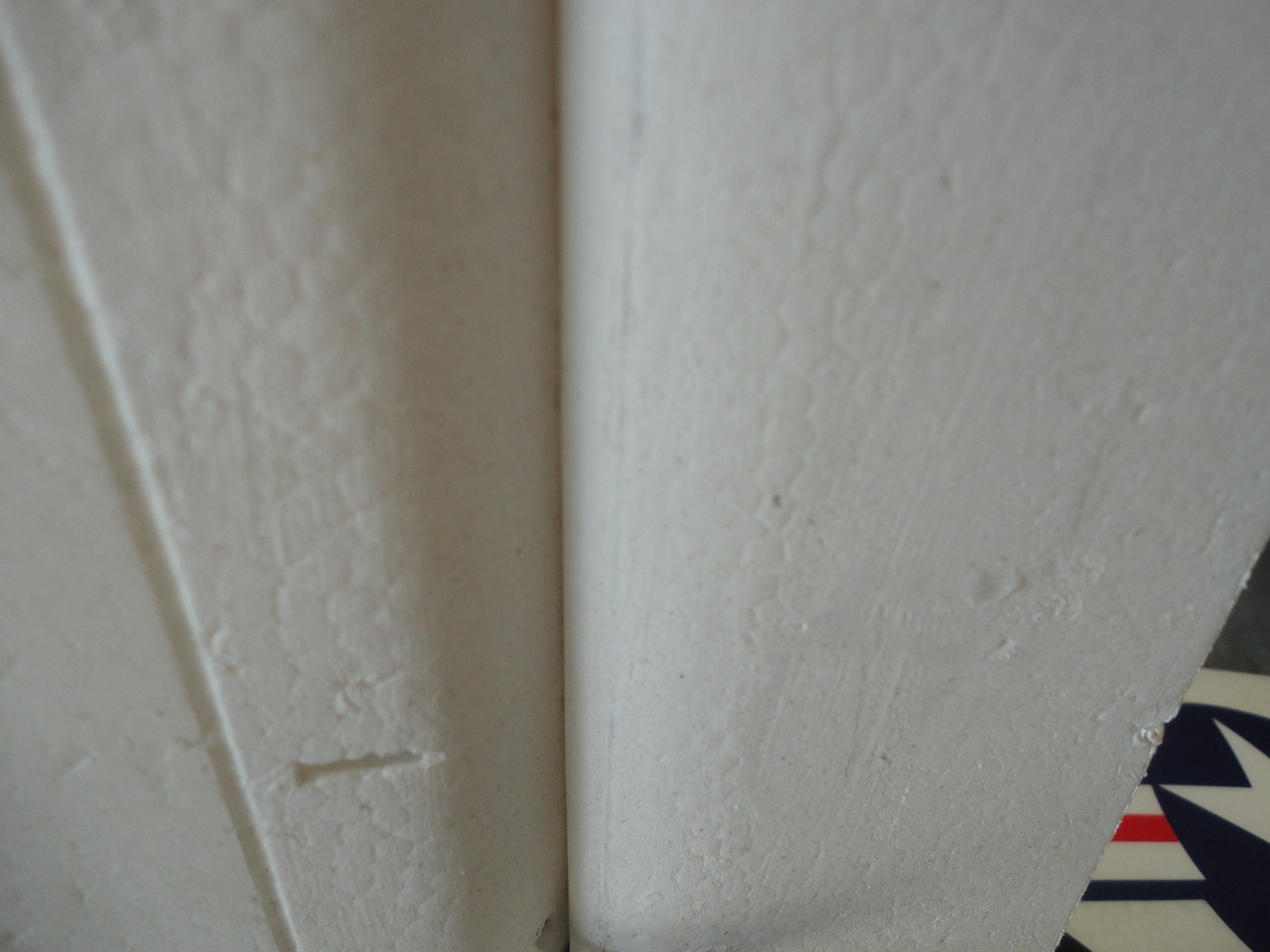
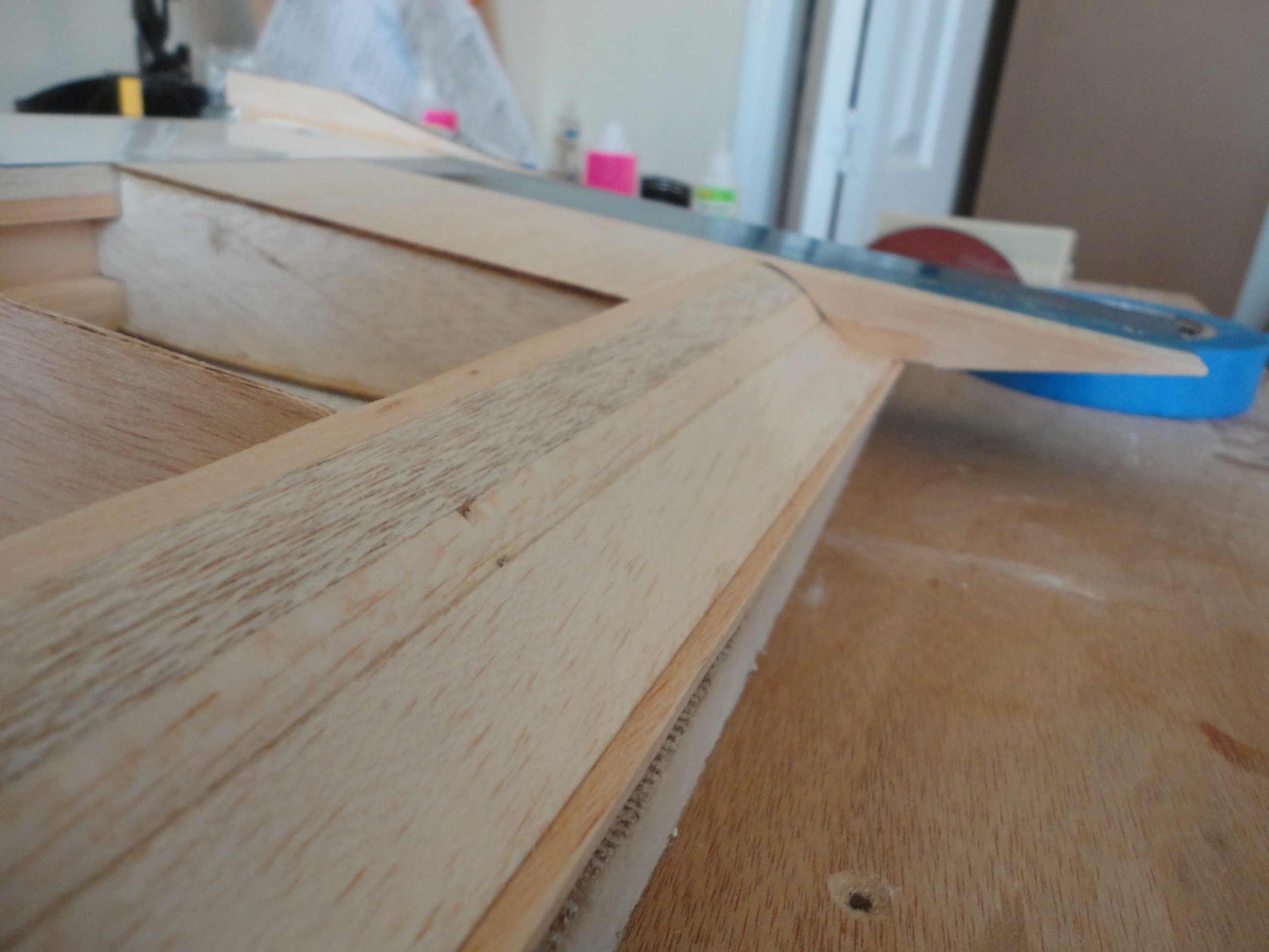
This will be the slot entry for our Senior Kadet.
Without any finishing/painting, it may seem like not much, but when you see it for the first time, your reaction may be unfavorable.............not to worry.
Slot Lip Extension
The Slot Lip Extension is an extension of the upper surface of the wing, which covers the first 25% or so of the flap. Its duty is to provide an aerodynamic structure, which aids in the creation of the very important slot. When deployed, the flap’s LE is just under and forward of, never aft of, the aft edge of the Slot Lip. This creates a convergent condition, which accelerates the airflow through the slot and aids in the creation of lift by the flap. A venturi effect, if you will.
The Flap Cove is the cutout area in its entirety, in which the flap resides. It includes, the Slot Entry and another radiused area, which I will call the “Flap Cove Radius” just under the slot lip extension. These two curved (radiused) areas, as I gather from reading the TR664, are the keys to allowing the smoothest airflow through the slot as the flap deploys.
In short(if you can believe it): smoother, rather than sharper, contours lead to the most effective performance of this flap design.
If you’re flying the hottest of ships with very high cruise speeds, then no, this configuration may not be for you.
For we brothers, flying the SR Kadet however, the benefits of “more lift for a longer period of time” outweigh the drag penalties.
Pontification complete.
Slot Entry and Flap Cove radius design and construction:
If you want, refer to the Technical Report as we proceed:
http://naca.central.cranfield.ac.uk/...report-664.pdf
Caveat: If building a new model, then it is a much simpler matter to merely modify your ribs, sanding or cutting the Slot Entry radius and Flap Cove radius as dictated by the wing chord.
For my SIG Seniorita in-work, I radiused the ribs for the Slot Entry and the Flap Cove as shown in the photos below. I used 1/32” balsa glued to the radiused areas and the Slot Entry and Flap Cove radii turned out quite nicely. Much simpler. If modifying an existing model as referenced here, there are many options/methods open as to how to fabricate the radiused areas.
 What follows is my method for the SIG Senior Kadet ARF.
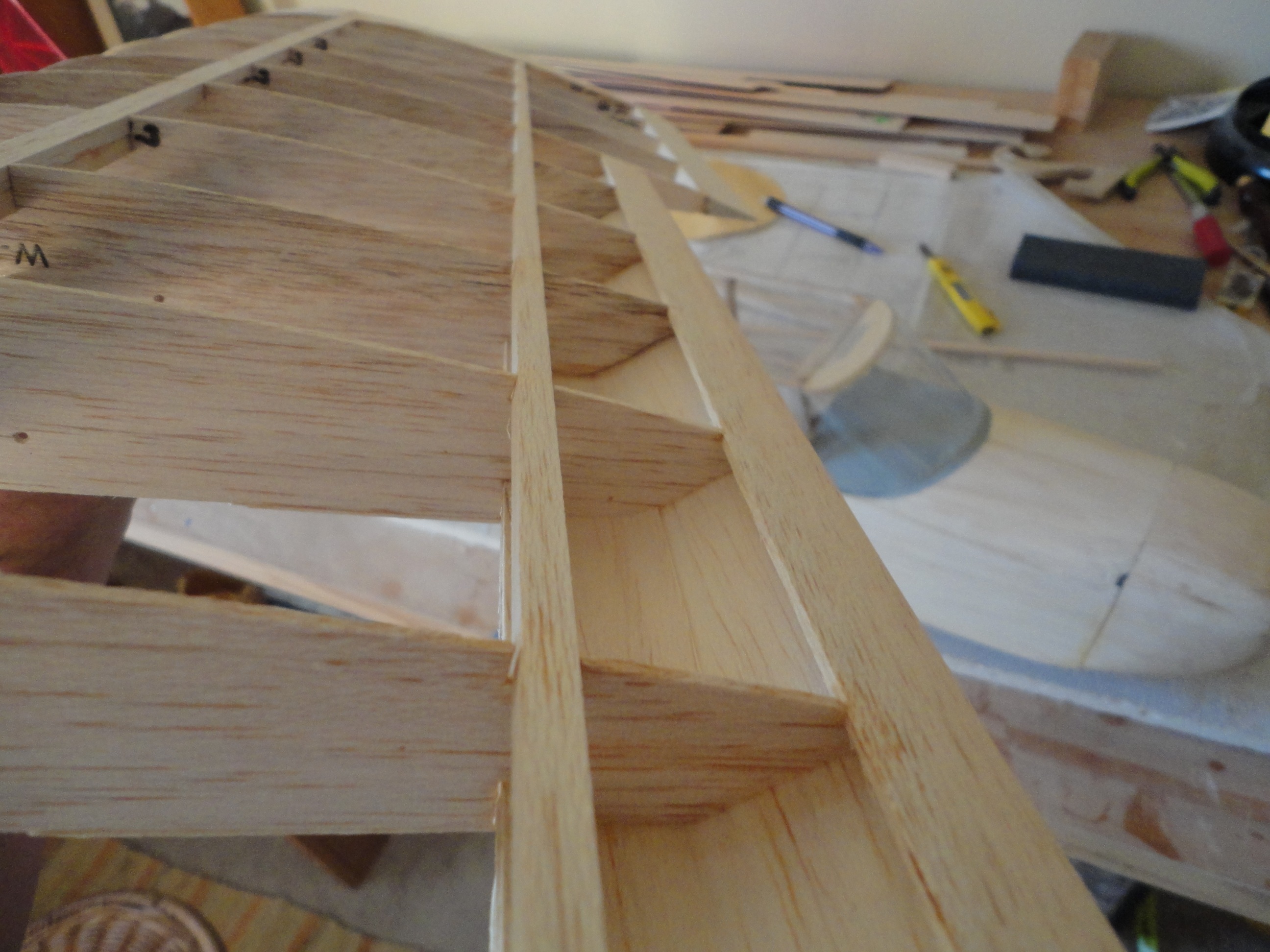
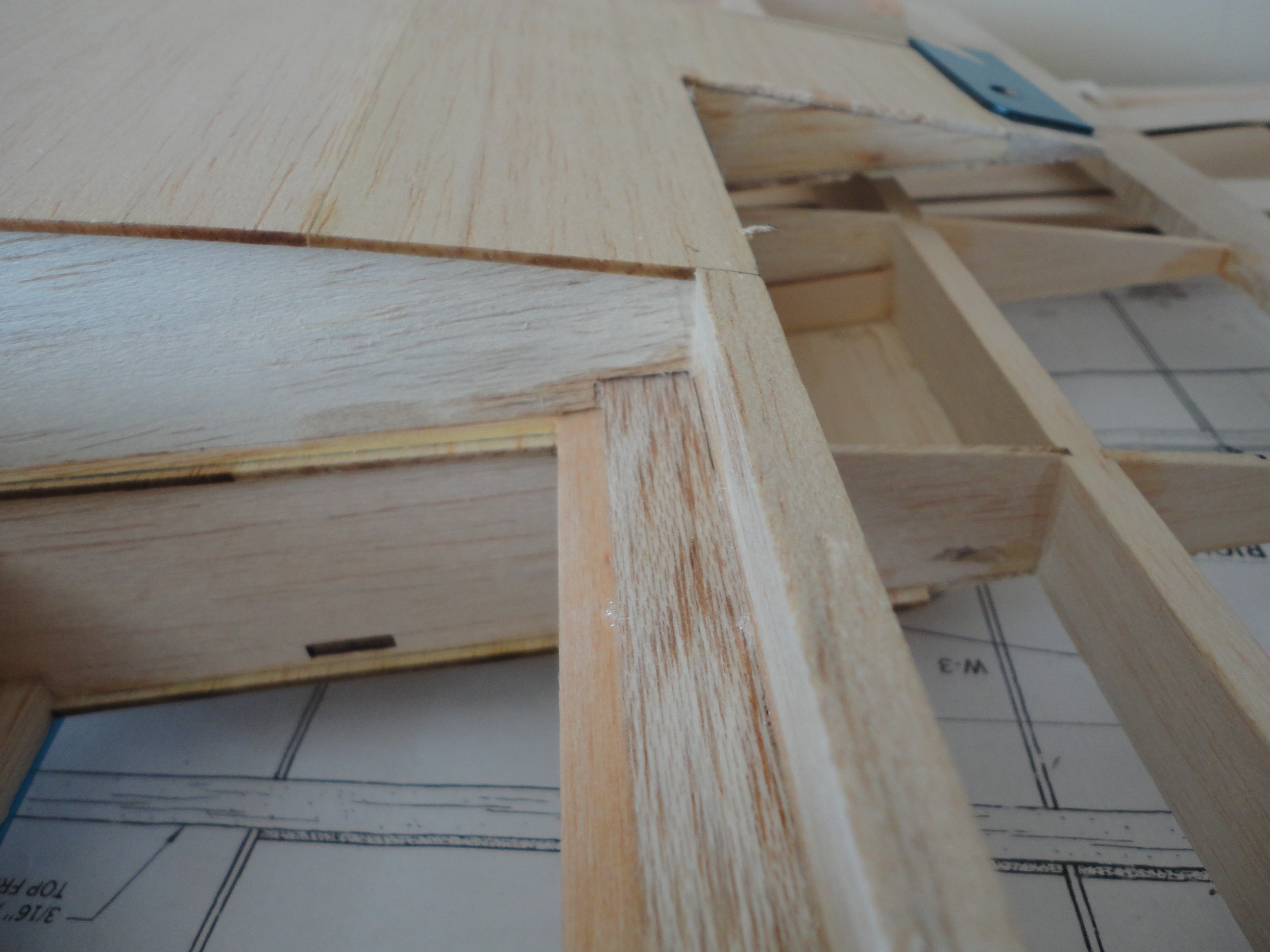
Since my aft spar is right in the Slot Entry area, I will be required to remove some material from the aft spar. I wanted to reinforce that area and maintain structural integrity. Figuring how much material would be removed when sanding the transition radius, I chose to go with balsa fill glued to the aft spar. I cut out the areas to allow the installation of 3/8” X �” and 3/16” X �” square fill pieces.
What follows is my method for the SIG Senior Kadet ARF.
Since my aft spar is right in the Slot Entry area, I will be required to remove some material from the aft spar. I wanted to reinforce that area and maintain structural integrity. Figuring how much material would be removed when sanding the transition radius, I chose to go with balsa fill glued to the aft spar. I cut out the areas to allow the installation of 3/8” X �” and 3/16” X �” square fill pieces.
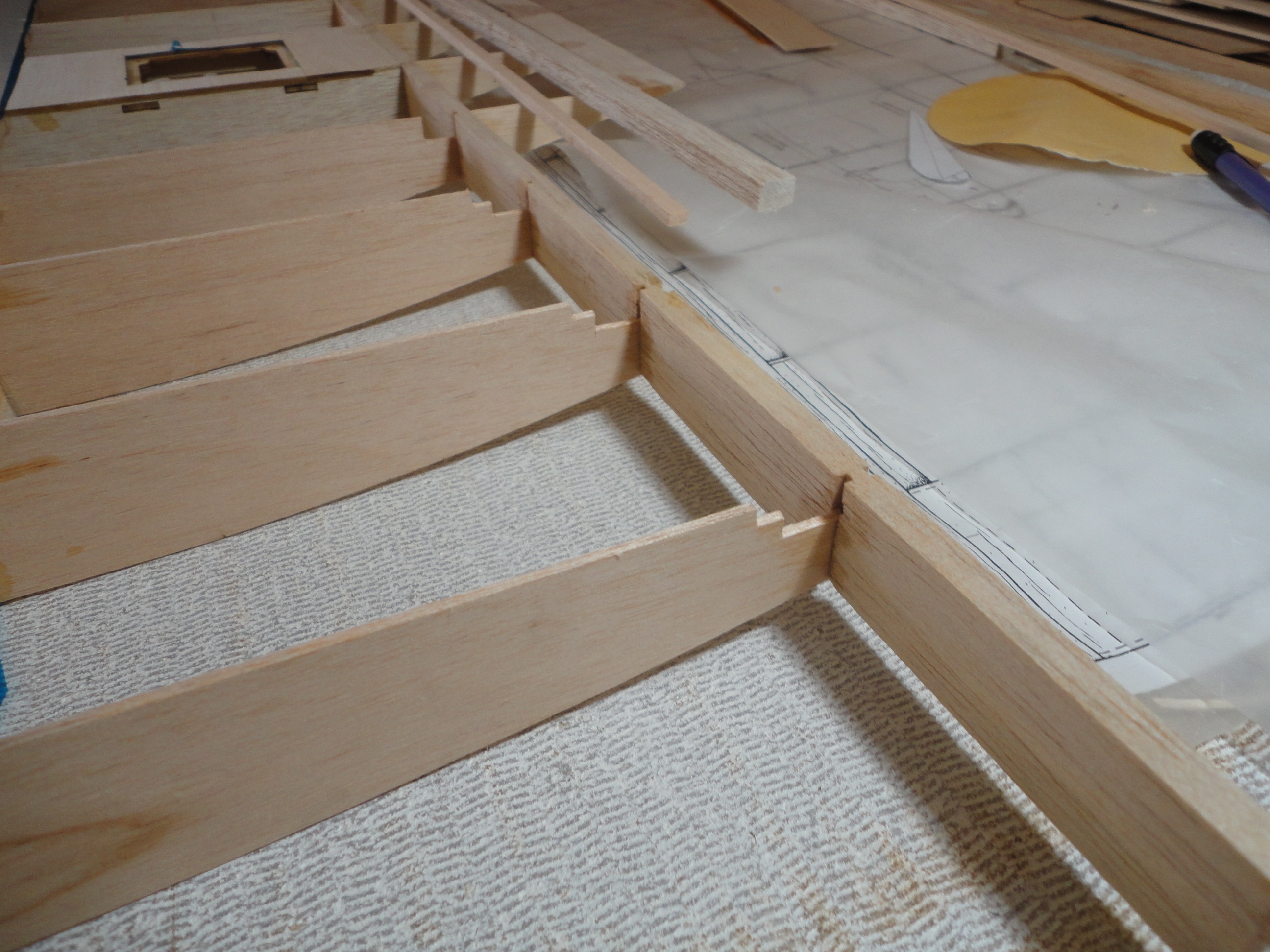
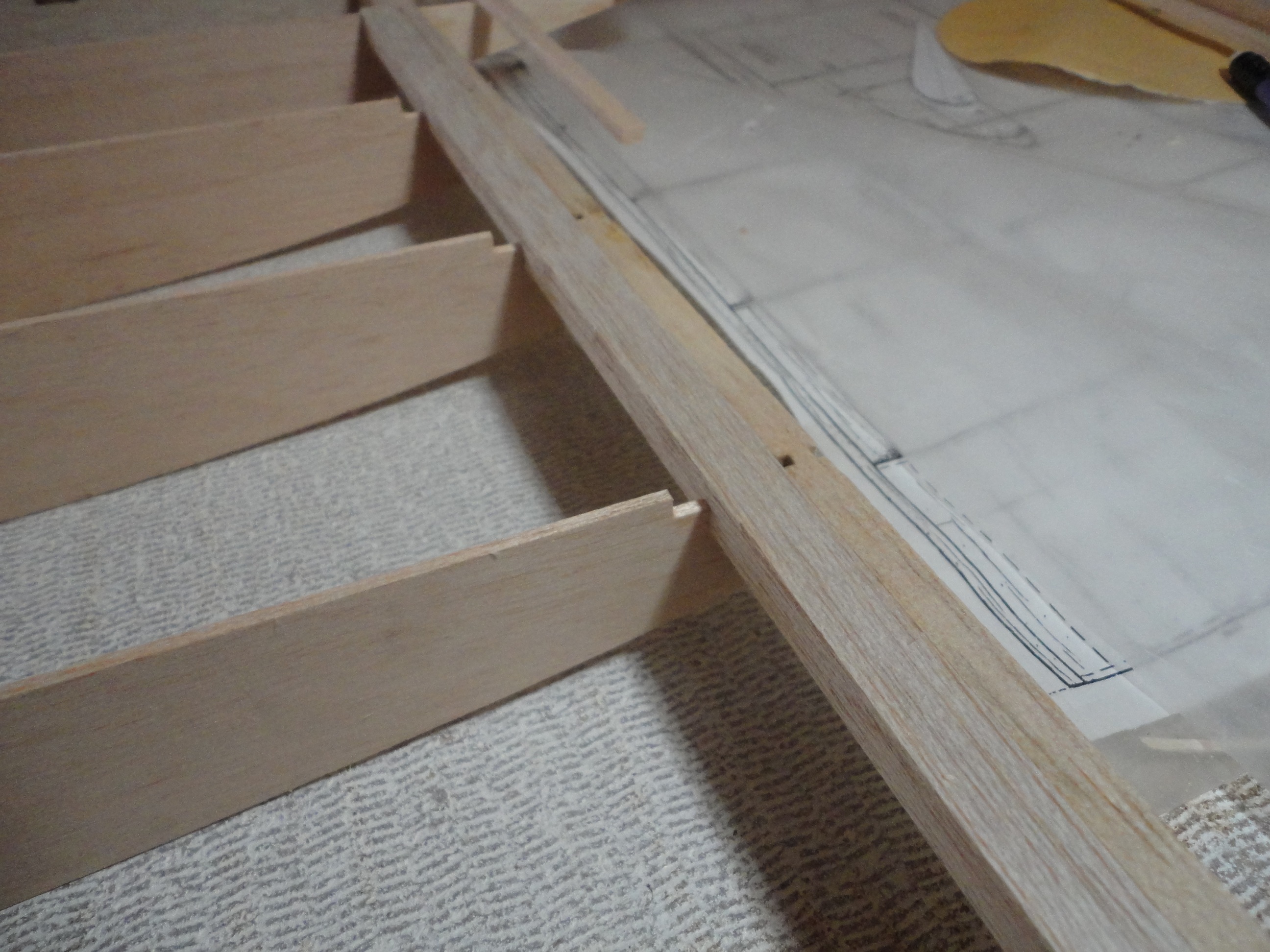
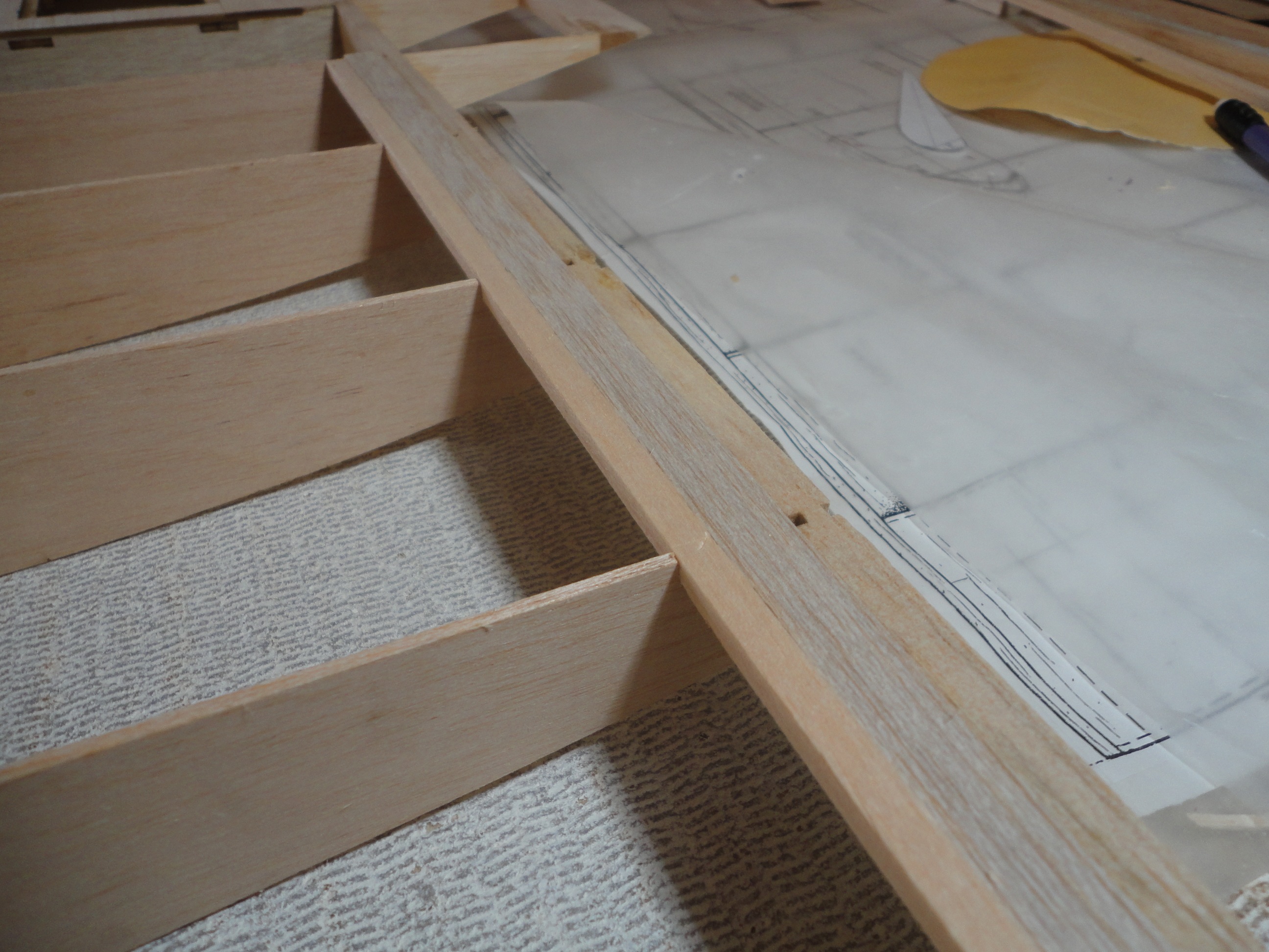
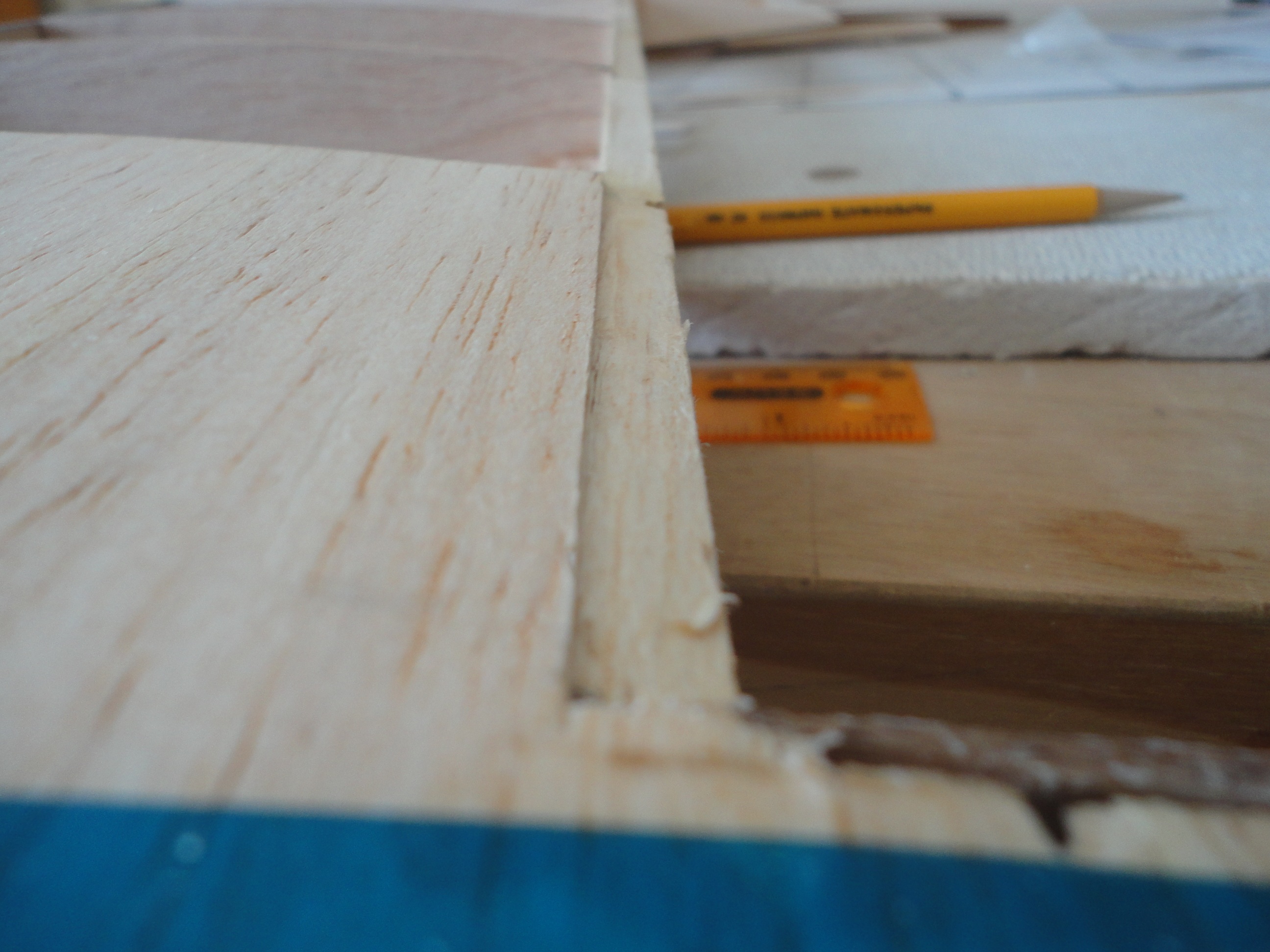
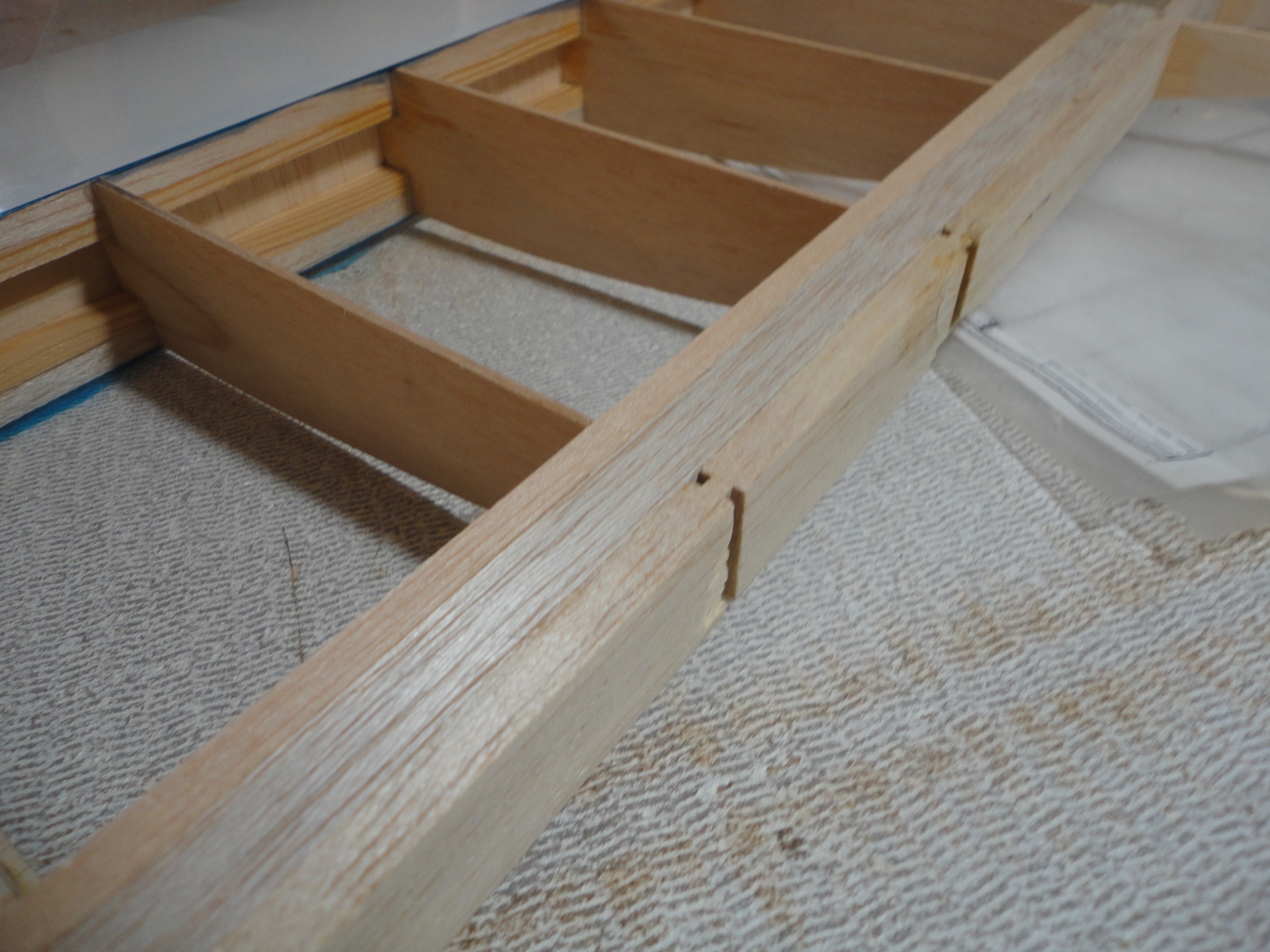 I glued these to the aft spar, the long dimension of both balsa fill pieces along the chord line. Reinforcement should be adequate and give me lots of room to sand in the Slot Entry.
Now it is time to sand the Slot Entry to shape.
I made a heavy card-stock template of the Slot Entry and Flap Cove radius. According to TR 664, the Slot Entry radius is:
Slot Entry Radius (R[SUB]e[/SUB]) = C X 0.0789
therefore: R[SUB]e[/SUB] = 15.0 X .0789 = 1.18 inches
and the Flap Cove radius is:
Flap Cove Radius (R[SUB]c[/SUB]) = C X .0811
therefore: R[SUB]c[/SUB] = 15.0 X 0.0811 = 1.21 inches
Virtually the same radius for both.
Remember: these dimensions are for the radius, not the diameter. I caution you, because no one cautioned me and I mangled one of my first attempts. Learning experience.
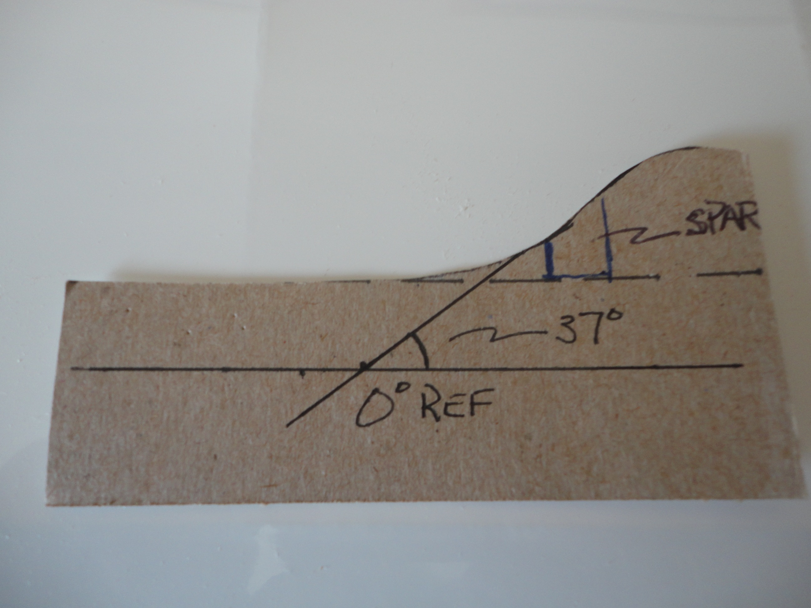
So grab your fancy Staedtler drafting compass, and get the lower and upper radius drawn out on your template.
Of note: refer to the TR 664 excerpt below: It shows that the changeover point from the Slot Entry radius to the Flap Cove radius is at 37 degrees from the lower surface of the wing.
I glued these to the aft spar, the long dimension of both balsa fill pieces along the chord line. Reinforcement should be adequate and give me lots of room to sand in the Slot Entry.
Now it is time to sand the Slot Entry to shape.
I made a heavy card-stock template of the Slot Entry and Flap Cove radius. According to TR 664, the Slot Entry radius is:
Slot Entry Radius (R[SUB]e[/SUB]) = C X 0.0789
therefore: R[SUB]e[/SUB] = 15.0 X .0789 = 1.18 inches
and the Flap Cove radius is:
Flap Cove Radius (R[SUB]c[/SUB]) = C X .0811
therefore: R[SUB]c[/SUB] = 15.0 X 0.0811 = 1.21 inches
Virtually the same radius for both.
Remember: these dimensions are for the radius, not the diameter. I caution you, because no one cautioned me and I mangled one of my first attempts. Learning experience.
So grab your fancy Staedtler drafting compass, and get the lower and upper radius drawn out on your template.
Of note: refer to the TR 664 excerpt below: It shows that the changeover point from the Slot Entry radius to the Flap Cove radius is at 37 degrees from the lower surface of the wing.
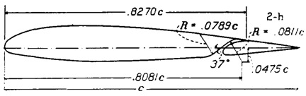
So, at 37 degrees from a line along the lower surface, transition to the opposite radius for the flap cove.
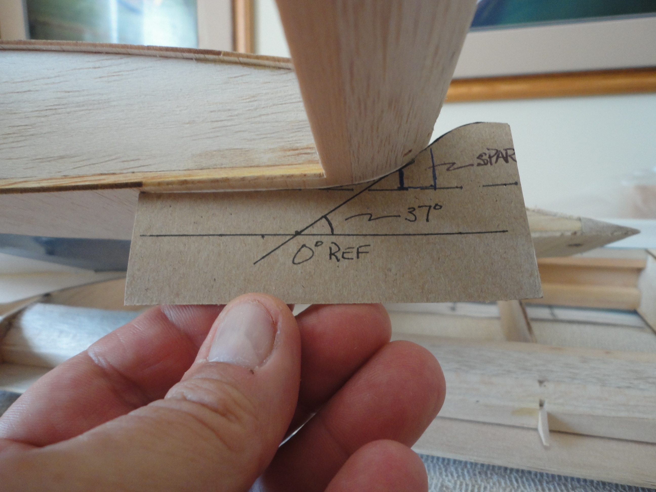
Grab your protractor and make your 37-degree angle as I did for my template.
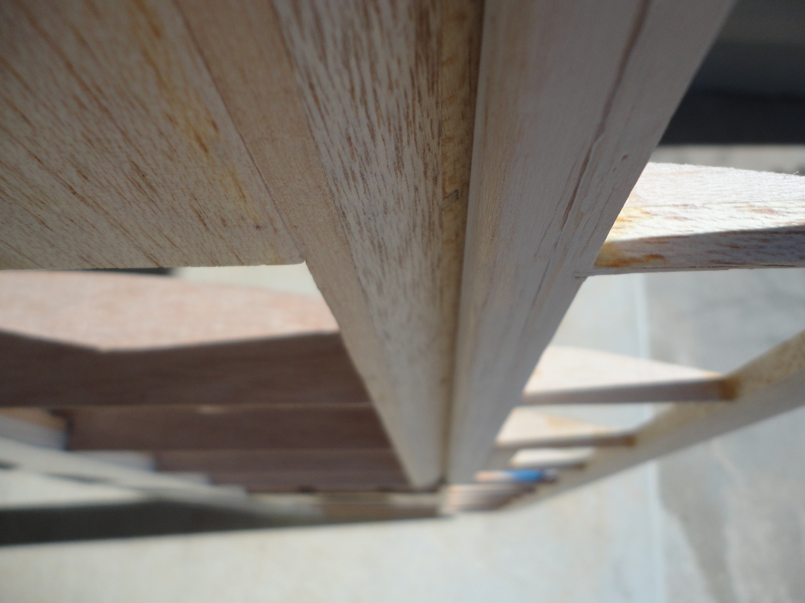
 Grab your template and when you finish making balsa dust, you should be here.
 Slot Lip Extension
The slot lip extension is balsa or thin ply extending out over the cove into which your flap will nest when fully retracted. At the very beginning of this series we found that
Slot Lip Extension (E) = C X 0.827
therefore: E=15.0 X 0.827 = 12.40 inches
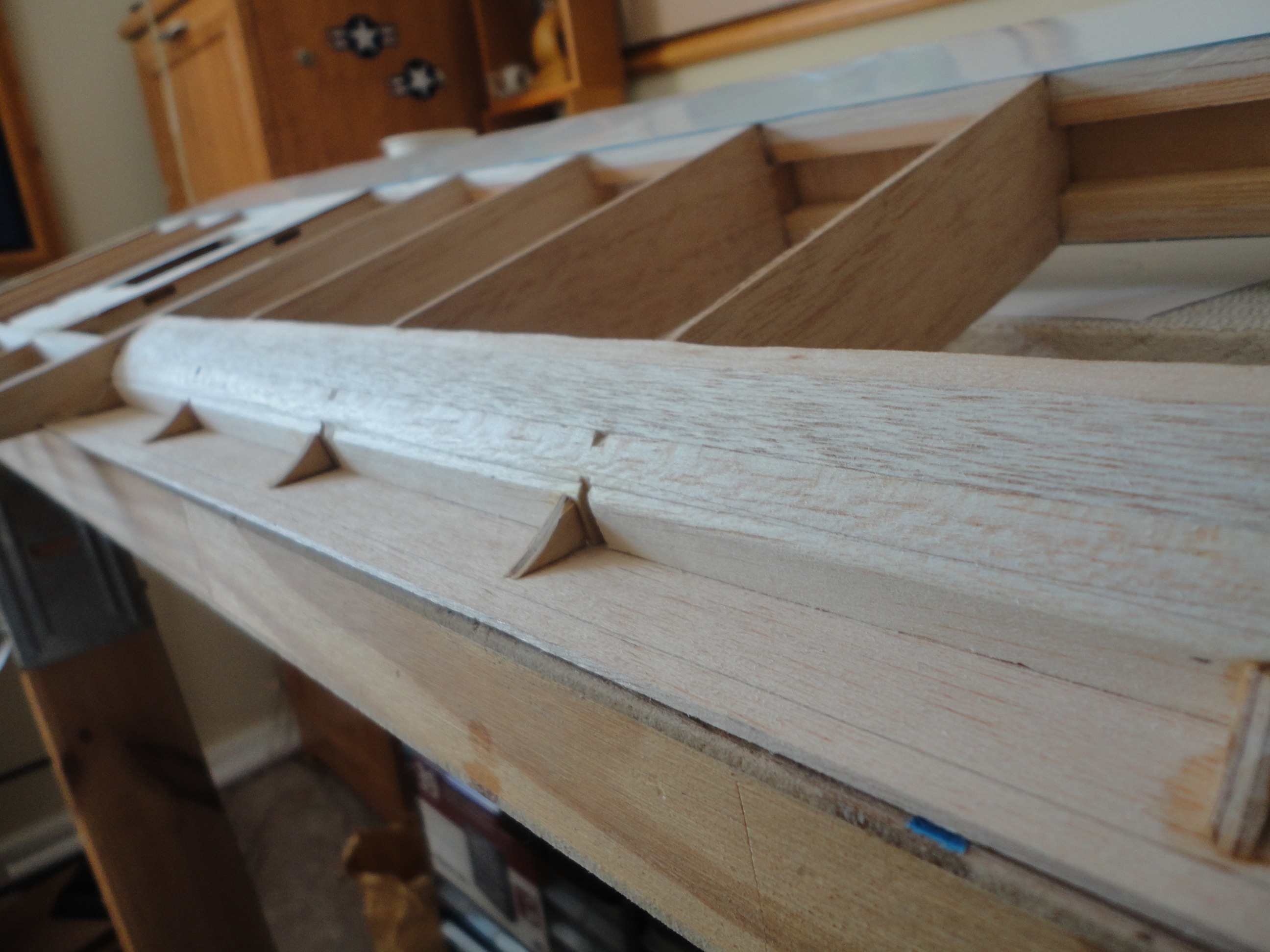
Therefore, my Slot Lip Extension will end 12.4 inches from the LE. Your numbers will vary according to your own Chord measurements. The Slot lip Extension should have a chord-wise dimension enough to make sure it engages all the structural components such as ribs and spars. I made mine out of 3/32 balsa 1.25 inches front to back. I will not have to worry about it flexing so much…..I will make some radiused gussetts to support the radius of the flap cove sheeting (discussed later) that will tie into the spar and Slot Lip Extension sheeting. When the flap cove radius sheeting is glued to the gussets and the underside of the Slot Lip Extension, it should be very rigid.
I want the Slot Lip Extension sheeting flush with the upper surface of the wing, so I’ll have to trim ribs and aft spar. I used my Dremel with a router attachment to route out the proper depth (3/32”) and then test fit the Slot Lip Extension.
Slot Lip Extension
The slot lip extension is balsa or thin ply extending out over the cove into which your flap will nest when fully retracted. At the very beginning of this series we found that
Slot Lip Extension (E) = C X 0.827
therefore: E=15.0 X 0.827 = 12.40 inches
Therefore, my Slot Lip Extension will end 12.4 inches from the LE. Your numbers will vary according to your own Chord measurements. The Slot lip Extension should have a chord-wise dimension enough to make sure it engages all the structural components such as ribs and spars. I made mine out of 3/32 balsa 1.25 inches front to back. I will not have to worry about it flexing so much…..I will make some radiused gussetts to support the radius of the flap cove sheeting (discussed later) that will tie into the spar and Slot Lip Extension sheeting. When the flap cove radius sheeting is glued to the gussets and the underside of the Slot Lip Extension, it should be very rigid.
I want the Slot Lip Extension sheeting flush with the upper surface of the wing, so I’ll have to trim ribs and aft spar. I used my Dremel with a router attachment to route out the proper depth (3/32”) and then test fit the Slot Lip Extension.
I will slightly taper the trailing edge of the Extension later and reinforce with thin CA.
Attention to detail is important here as well.
Remember the requirement, mentioned in the Technical Report, of having the flap upper surface of the flap come as close as possible to the Slot Lip Extension trailing edge? This close fit will serve as a “seal” to prevent airflow (and excess drag) when the flap is fully retracted.
 Flap Cove Radius
The final thing to do today is form the upper radius radius for the flap cove.
Earlier, I determined that this radius is:
Flap Cove Radius (R[SUB]c[/SUB]) = C X .0475
therefore: R[SUB]c[/SUB] = 15.0 X 0.0811 = 1.21 inches
I discovered that a 2” diameter PVC pipe has a 2.5-inch outer diameter. (2” inside diameter plus .25” walls). I need a radius of 1.21”, but I figure 1.25” radius is close enough. I mean, what’s 4 one-hundredths of an inch? I hate to depart from my typically anal-retentive approach at this point, but I am willing to negotiate.
I’m going to make gussets with a radius so that I can use them to support both my Slot Lip Extension, and use the radius to glue my 1/32” balsa sheet to.
Flap Cove Radius
The final thing to do today is form the upper radius radius for the flap cove.
Earlier, I determined that this radius is:
Flap Cove Radius (R[SUB]c[/SUB]) = C X .0475
therefore: R[SUB]c[/SUB] = 15.0 X 0.0811 = 1.21 inches
I discovered that a 2” diameter PVC pipe has a 2.5-inch outer diameter. (2” inside diameter plus .25” walls). I need a radius of 1.21”, but I figure 1.25” radius is close enough. I mean, what’s 4 one-hundredths of an inch? I hate to depart from my typically anal-retentive approach at this point, but I am willing to negotiate.
I’m going to make gussets with a radius so that I can use them to support both my Slot Lip Extension, and use the radius to glue my 1/32” balsa sheet to.
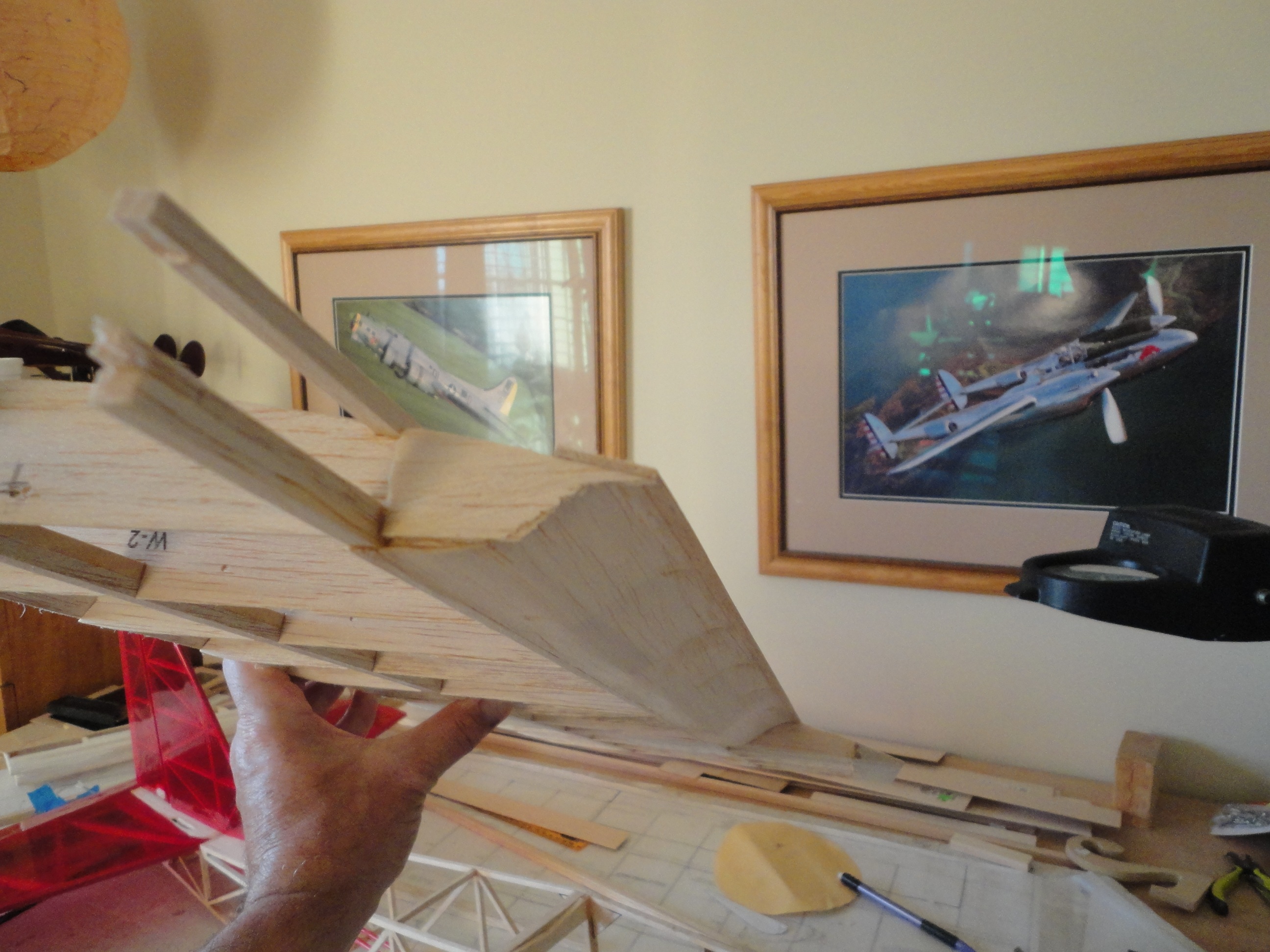
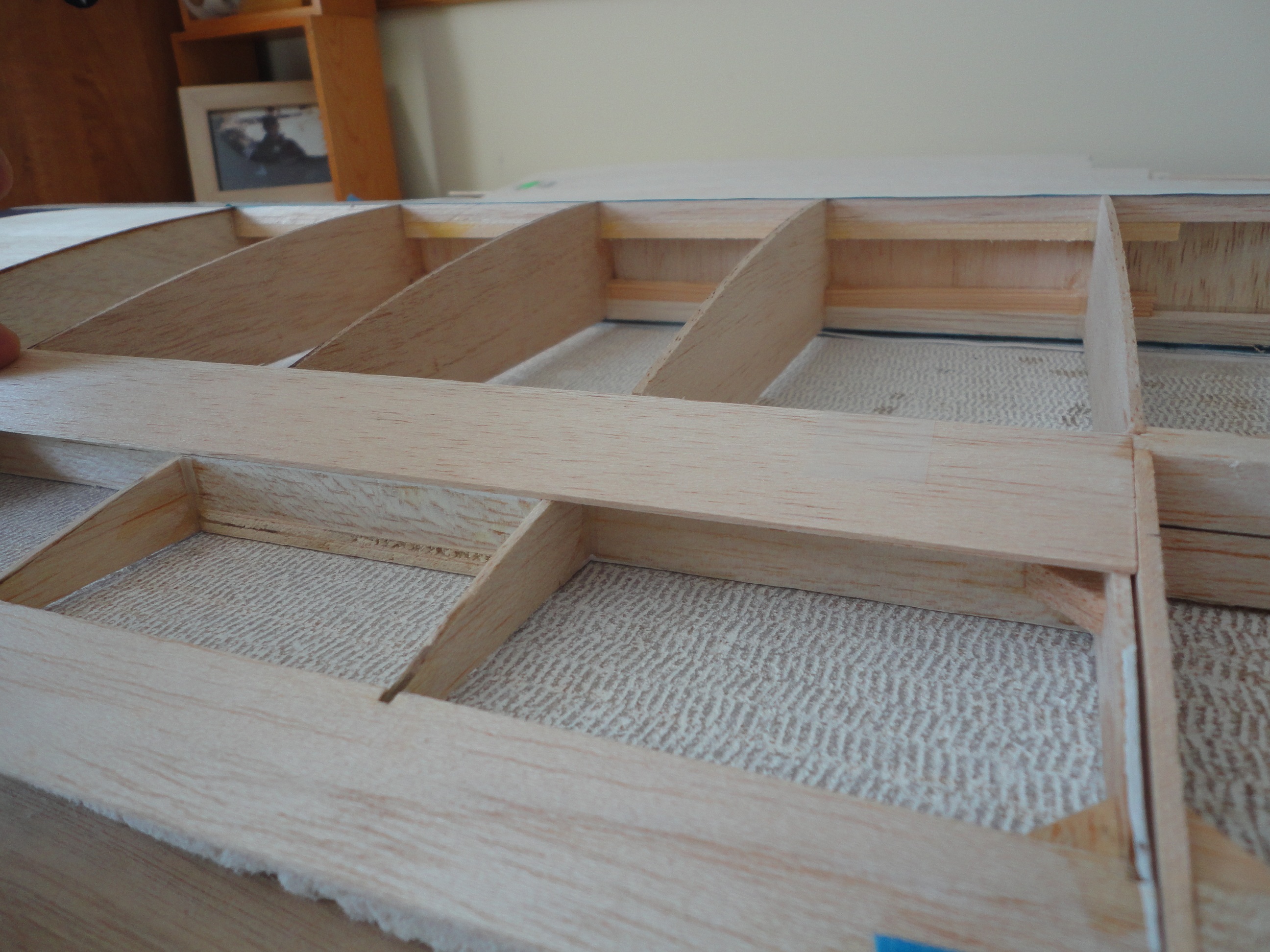
 Gussets installed, ready for the Flap Cove Radius sheeting.
When installing the Flap Cove Radius sheeting, I used epoxy to make sure I could make the sheeting end up where I wanted it before everything became fixed in place.
1/32” sheeting works just fine for making the flap cove radius.
Gussets installed, ready for the Flap Cove Radius sheeting.
When installing the Flap Cove Radius sheeting, I used epoxy to make sure I could make the sheeting end up where I wanted it before everything became fixed in place.
1/32” sheeting works just fine for making the flap cove radius.
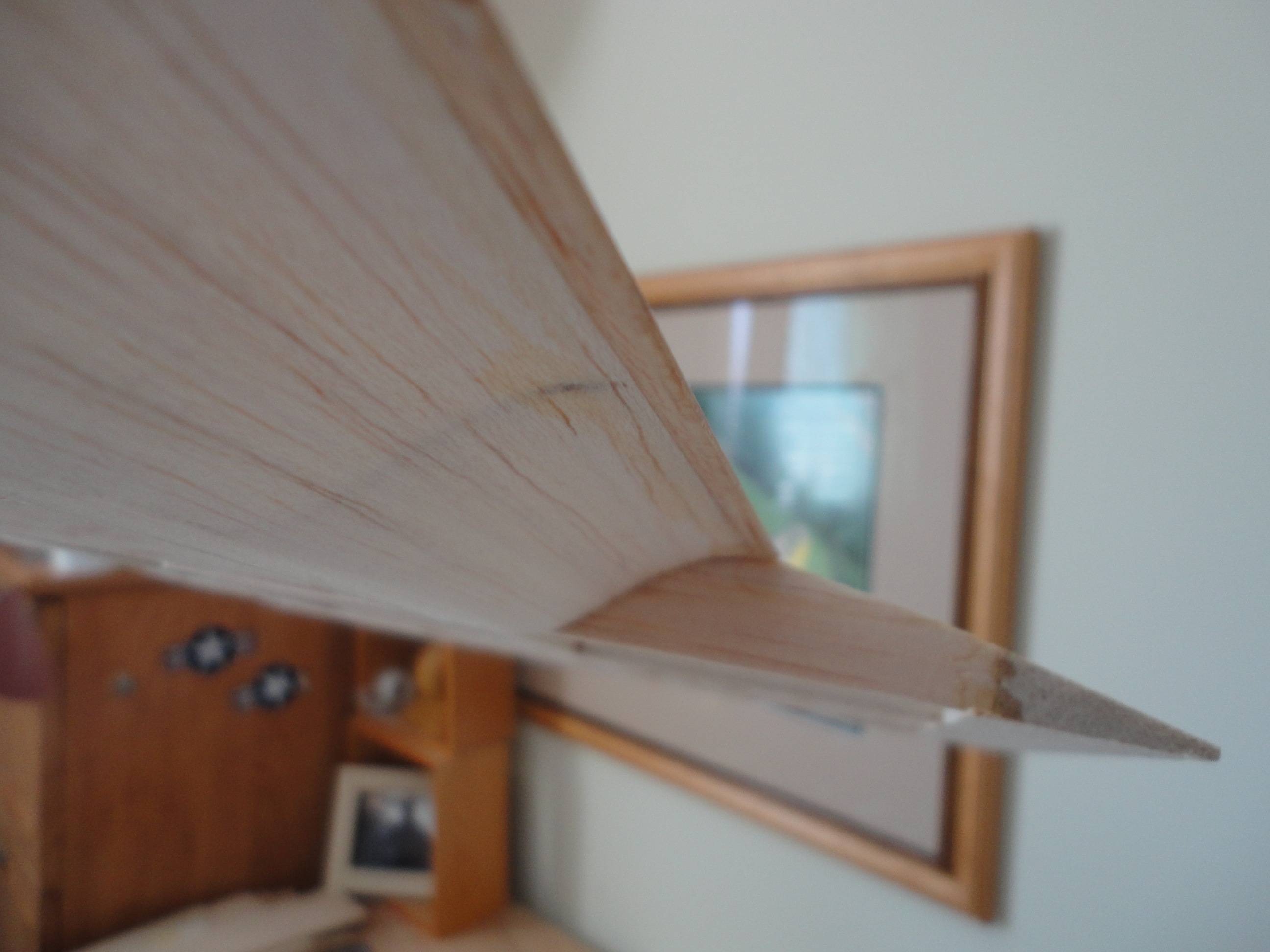
Fit check complete……just fine.
Hinge mount test fixtures and final flap hinge mount locations come next……………………………
thanks for reading..........nm