
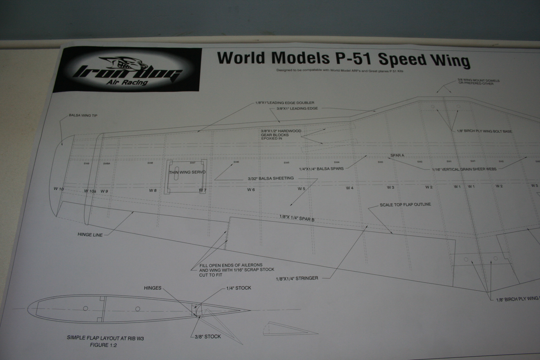
 Sample view of wing plans, left panel
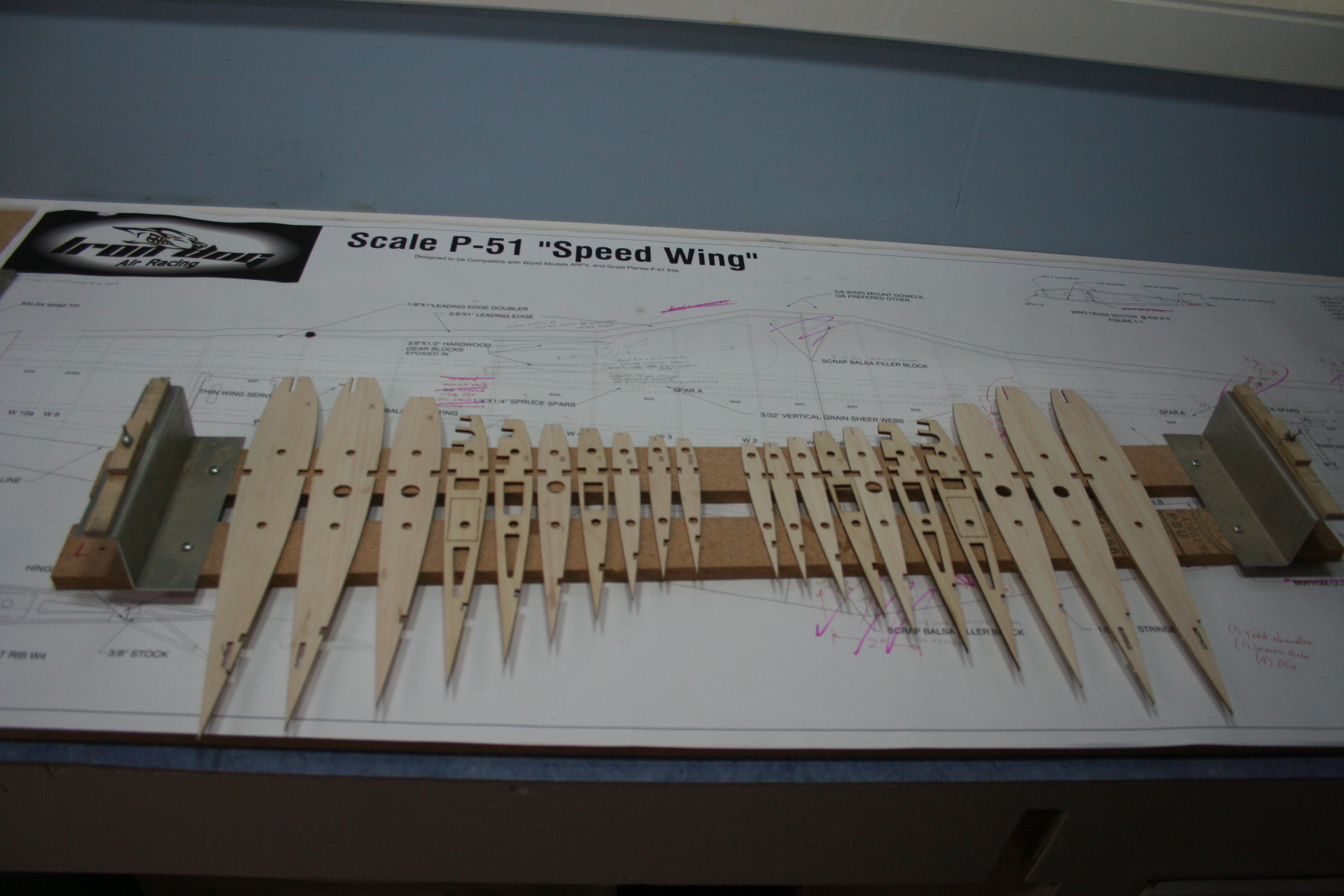 Ribs laid out on wing jig.
Initial planning stages:
Make some decisions regarding which version is to be built:
- Scale 55 5/8� full-span at 555�[SUP]2[/SUP] wing area; or, Reno race-modified clipped-wing 50 3/8� version at 519�[SUP] 2 [/SUP]wing area (�The Galloping Ghost�, �Stiletto�, or similar)
- With, or without, flaps.
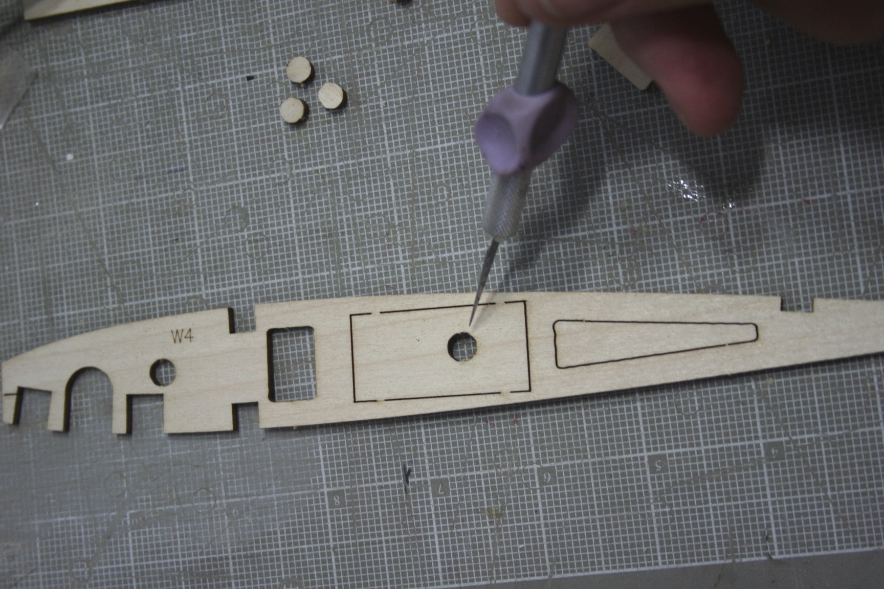
- Either way, do NOT remove the servo cut-out, as the rear drill rod/carbon fiber rod must pass through the hole located near the center of the cut-out (see picture below). If flaps are used, the cut-out is removed only after sheeting the wing.
- If scale flaps are desired, they will cut into the 1/8� birch ply wing bolt base, at the root of the wing. The ends of this bolt base would need to be shortened so that it does not extend to the scale outline of the flap; and to secure it, scrap balsa would need to be incorporated, attaching it to the top sheeting of the wing, rather than to rib W2. (Or some other preferred method for wing attachment incorporated.)
3. Are the aileron servos able to fit within the cutouts of plywood rib W7, and mount directly to this rib? Or, will larger servos be installed within the bay W7-W8, and attached to aileron hatch doors?
- Plans show the latter method, with servo arm opening more towards the center of the control surface.
- If the servo is to be mounted directly to the plywood rib, the hatch orientation shown on the plans will likely have to be reversed, with the opening for the servo�s output-arm oriented towards the root of the wing (and perhaps some minor repositioning of the ply hatch mounts may be necessary to better align the hatch with various servos� output arms). Additionally, if this mounting method is chosen, it is much easier to mount the servo to the rib now � prior to construction of the wing. Taking this step now eases both the mounting of the servo, and the running of the servo wires through the wing panel.
4. Will scale dihedral be used?
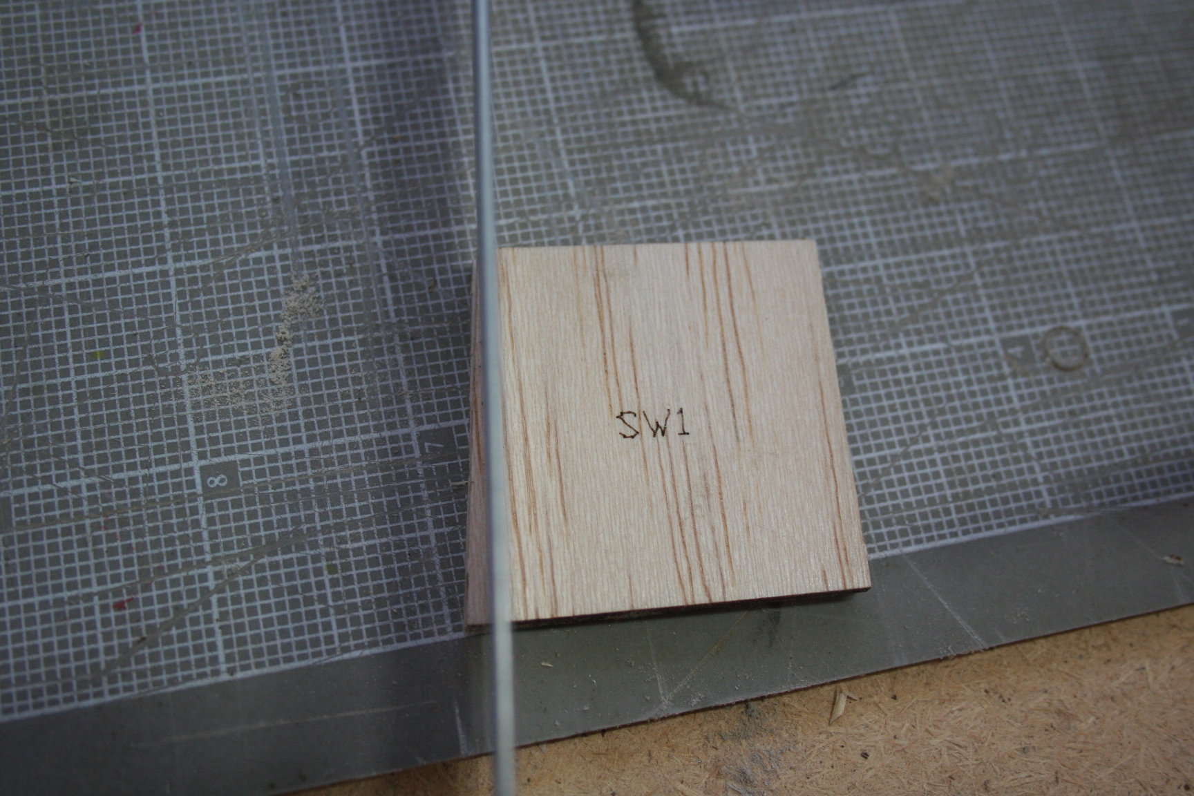
Shear web W1 and the dihedral brace were designed with scale dihedral built into the wing. Some racers prefer to sacrifice the stability of scale dihedral in favor of other perceived benefits of a wing with less dihedral. (Some racers argue that a wing, so designed, �carries more speed through the turns�; but I have yet to find a study by a degreed aerodynamicist that verifies this.)
If you decide you want less dihedral, you will need to lessen the angle in both SW1s equally, and then lay them together to trace out and cut a new 1/4" thick, plywood dihedral brace.
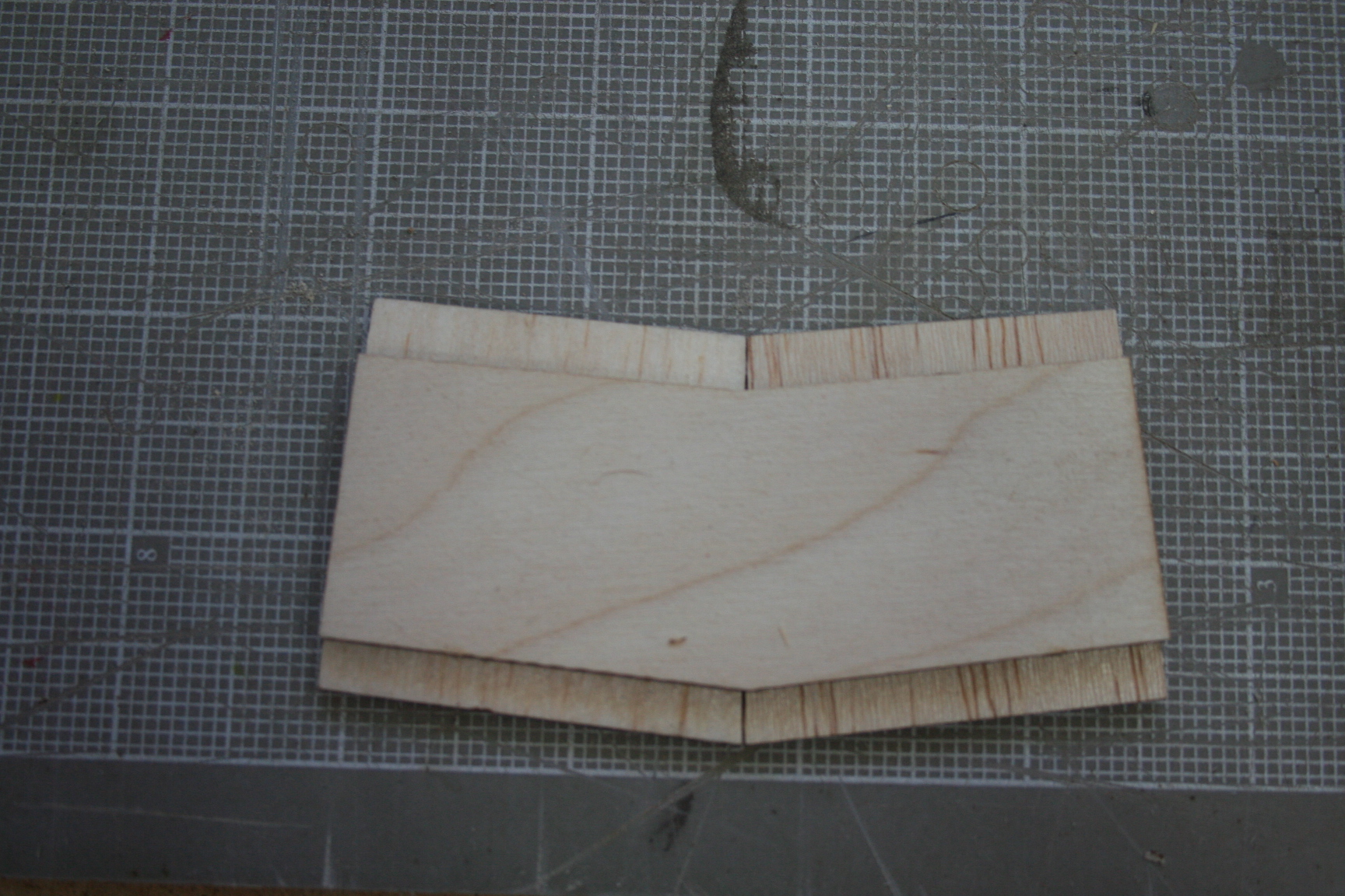
Please note:
The dihedral brace is 1/2" less in height than the shear webs to accommodate fitting between the two 1/4" top and bottom spars. For a proper fitting dihedral brace, you will need to subtract 1/4" from both the top and bottom of the pattern. When completed the new dihedral brace would appear as if vertically centered between the shear webs. (Accompanying picture is only for illustration purposes and therefore utilizes the unmodified dihedral brace and shear webs.)
Last edited by Iron Dog; 02-27-2015 at 11:59 PM.