
Sheeting the Top of the Wing:
7. When finishing the forward section, I foresee different builders having different preferences, but I would like to share some previous experience to consider before you start. When I built the very first prototype, I glued the 1/8" by 1" leading edge doubler to the leading edge before sheeting and beveled the doubler to the contour of the ribs, prior to sheeting. I then used one long, wide 3/32" sheet in one piece to sheet the remaining forward section of the wing, because I wanted the extra rigidity from having that sheet run the full span of the wing. I was not happy with the result. This final sheeting piece had to be forced to take too many compound curves, and even with relief cuts and wetting it down, it still resisted conforming well enough. Pressing so forcefully onto the wing jig to try to keep the tension from popping the sheeting off of the ribs while the glue set was not exactly conducive to keeping the entire assembly straight and true. Because of the strength of using both carbon fiber spars and the three spruce spars running the full span of the wing, I realize the relatively minute amount of extra strength from the sheeting is not worth the trouble, so I decided to try a different approach this time � and am pleased with the results. If you are leaving in the CF rods, the following steps (A - G) would be my recommendation:
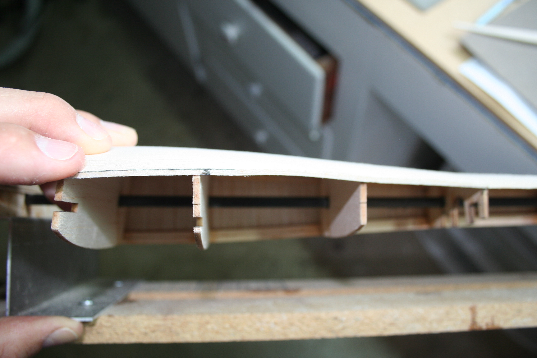 Jumping ahead in the construction a little, this view gives an idea of the complex curvature that the front sheeting must conform to as it progresses from the extra-tapered root section. It is caused by the substantially elongated and therefore much larger root ribs, compounded by the thicker airfoil used by these root ribs of the stock World Model and Great Planes wings, which must be used to fit the saddle of stock fuses without having to build a crutch system (ribs W1 and W2 are visible on left), as it progresses to the thinner airfoil and more"normal" length standard taper section (ribs W3 and W4 are visible to the right). This complex curvature makes gluing a wide, one-piece sheet across the full length of the panel, without unintentionally causing a warp or bow, a very challenging undertaking.)
Last edited by Iron Dog; 03-09-2015 at 09:31 PM.