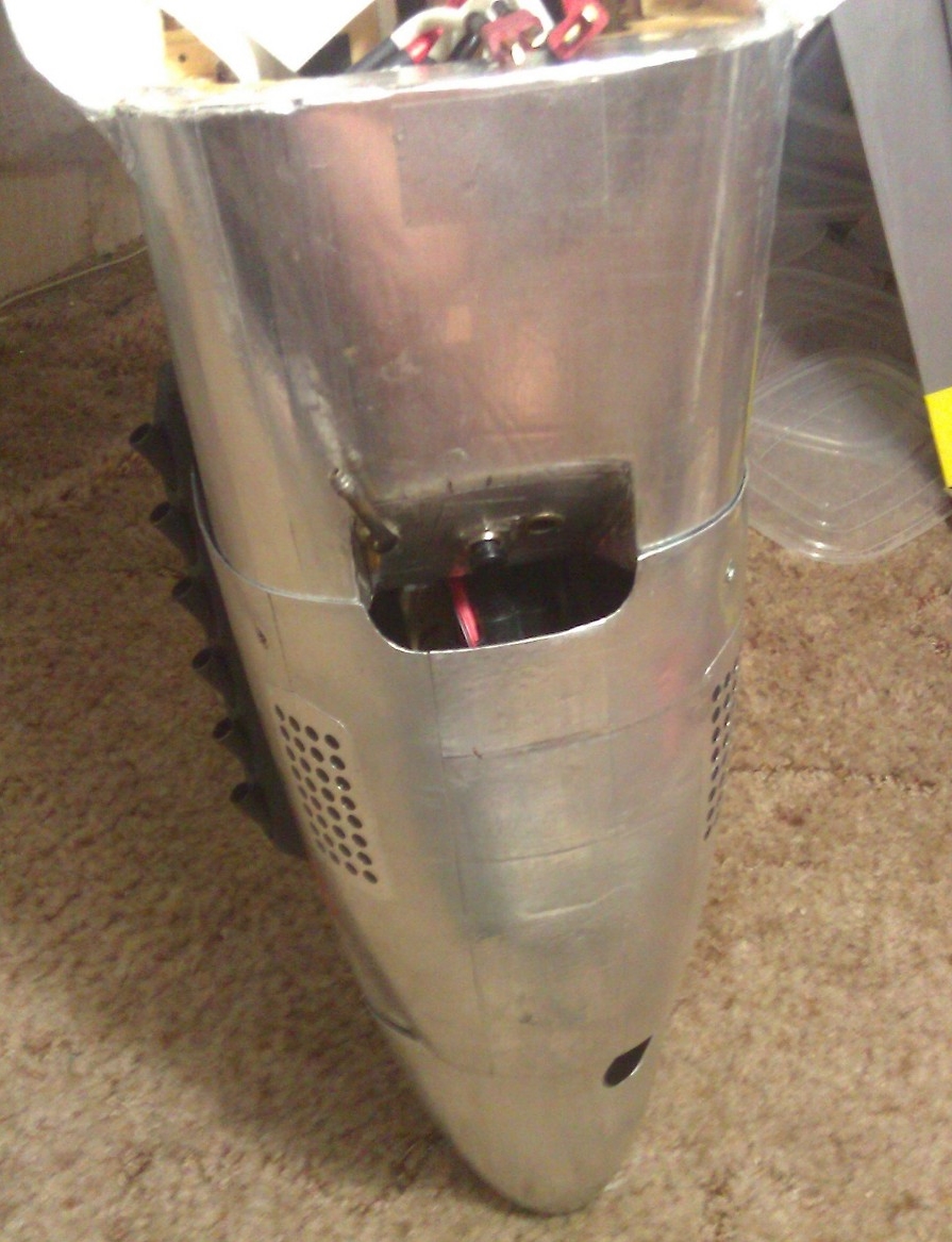
This is the nose exhaust of my TF GS P 51 B.

You need to really look at a Mustang's shape. Because the air flow around the entire aircraft is spiral (due to the prop dragging air around with it), centrifugal force causes air to move out away from the skin creating a low pressure air mass that reattaches further back near the wing. Openings near the front (back to a few feet behind the nose of the full scale) are under pressure and openings behind the curve (where an opening can't see the spinner) are in low pressure. The area of this opening is approximately 2.5 times the chin scoop.
The main body of spiral airflow (spiral air flow is the reason the leading edge of the vertical fin is offset a few degrees to the left) is forced by the air that it compressed when the spinner charged through it to rebound, pushing the boundary layers against the fuselage and forcefully squeezing the rear of the aircraft and recovering a lot of the original energy that the nose expended when it pushed through. This is some times called the "Pumpkin seed effect", and is the point in the airframe's operating envelope that, having reached this speed (fast cruise), it takes less power to maintain this speed (best cruise speed for fuel economy), a feature the P 51 had that a lot of other planes could not duplicate. It took some pretty smart guys to design this plane and they didn't get it completely right until the B-C models were produced.
Changes made to the design for the D model (visibility(bubble canopy), thicker wing (6 upright machine guns), and the chin carb-air-scoop (Packard-Merlin)), made it a better gunfighter but actually slowed top speed under 10,000 feet.
The common P 51 model designs have a box fuselage and these airflow factors are minimal.
The H-9 P 51 design has an almost constant curve to the fuse from nose to tail (except the area around the sides of the cockpit, this area is also the flattest part of the full scale fuse) and should show better efficiency than its competitors.
The above picture shows the simple hot air exhaust I have been using for about ten years on 5 of the 6 TF GS Mustangs I have flown in the last 11 years. It is cut out of the lower firewall and is 1.5 inches deep and 3 inches wide. It has rounded edges inside except for the front edge on the back of the cowl. High velocity air flowing past the opening exerts a drag effect that pulls the slower air coming out of this vent. The same aerodynamic principle used for slotted and fowler flaps on wings. If you put a spoiler here you upset the air flow and create drag.
The engine cowling in the picture is for the large electric motor I'm flying now. I have used this same exhaust on a Fox 2.4, A ZDZ 80, And twice with my DA 50R. The other cowls for the gas engines had exhaust stack openings that were just large enough to avoid damage from hot mufflers and of course the top of the gas engine cylinder. I also filled in the area behind the chin scoop with block balsa and created an aerodynamic air passage to carry the cool air directly to the engine cylinder. No overheating. And it is not visible unless you look at it from this angle.