Spent a long day in the garage today. It was raining anyway so a good day to work on the Rascal.
I want to back up a bit first.
Yesterday, after I had uploaded the pictures, I chucked the 8-32 engine mount screws in the drill press & used a mill file to taper the ends to make a "lead". This will help prevent cross threading in the soft nylon. The nylon is plenty strong to hold the screws given the long thread section.
Now for the progress today.
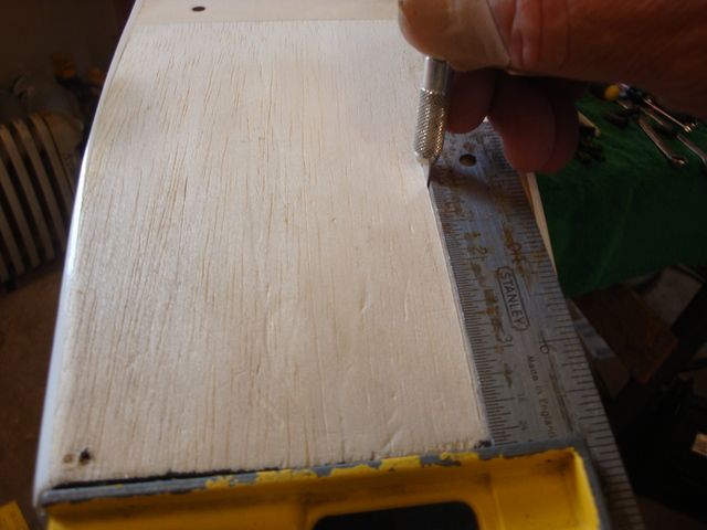
I started out by laying out the thrust centerline W/masking tape.
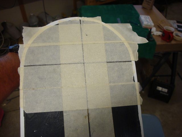
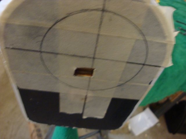
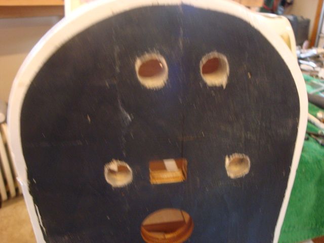
Then, I laid the mount over the centerlines & using the witness marks cast into the mount to locate it properly, I traced around the perimeter. I also cut the masking tape from the square hole that is in the firewall.
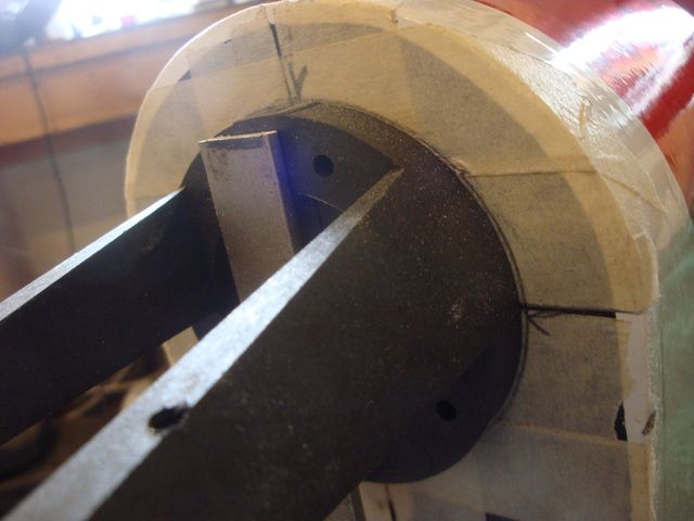
I used a piece of scrap 1/8" aluminum, a stove bolt & a wing nut to clamp the mount in place over the marks made on the tape.
W/the engine clamped in place, I was then able to make cut-outs to the cowl.
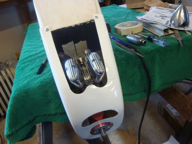
As it turned out, I had to rotate the mount a few degrees clockwise to get the cylinder head centered in the bottom of the cowl.
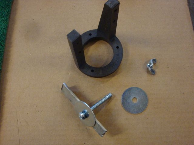
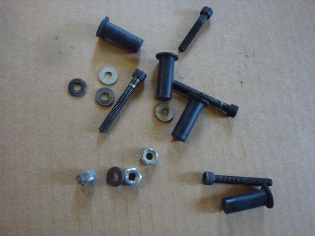
Here are the components needed to make the vibration dampening mount. There's probably about $6 worth of hardware there.
After I drilled the clearance holes form the 10-32 screws through the mount & firewall, I removed the clamped on mount & opened the holes up to 3/8" to clear the rubber well nuts & nylock nuts.
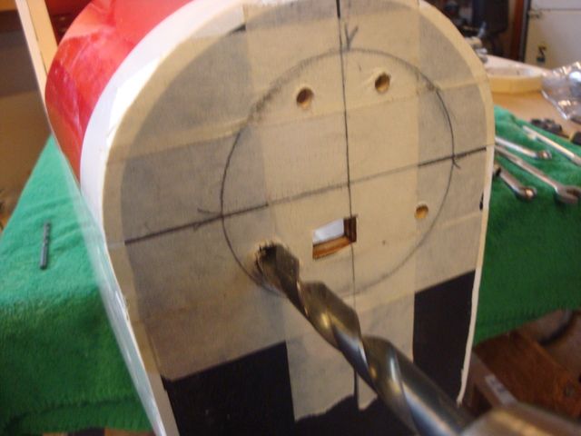
Here is the firewall with the holes prepped for the well nuts. I used a small grindstone to smooth out the edges of the holes.
I cut a hatch opening from the firewall to the 1st cross member. This will be used to house the CDI module as well as allow access to the back of the firewall to hold the nuts as the mount is tightened down.
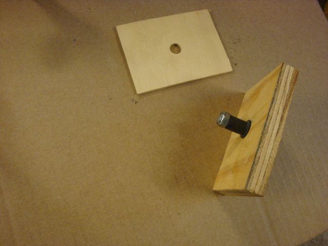
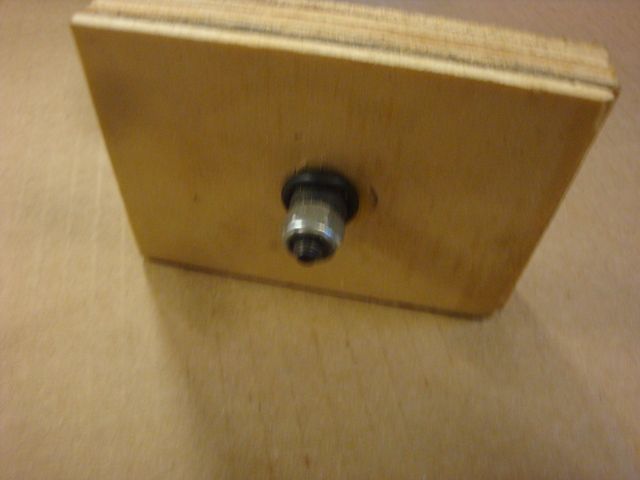
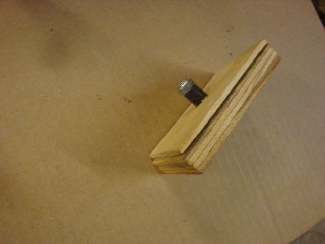
Somehow I lost the PIX of the assembled mount before I inserted it into the firewall. I did a mock-up W/some plywood. The 3/8" ply represents the mount, the 1/8" the firewall.
First you assemble the bolt & well nut & screw the nylock nut down finger snug onto the end of the well nut. You don't want to swell the side of the well nut. Just assemble finger snug.
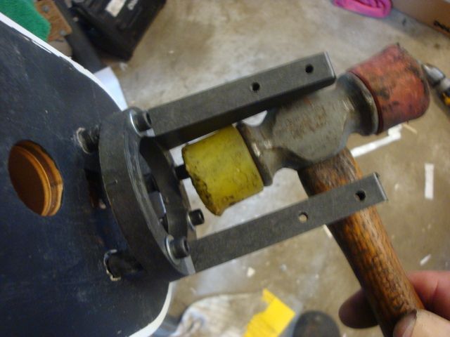
Insert the assembled mount W/the well nuts & nyloc nuts into the prepped holes in the firewall. The nyloc nuts will be slightly tight so I used a plastic mallet to tap the screws through the firewall working each one a little at a time until the mount slips up against the firewall.
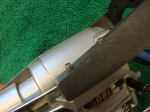
Now all you need to do is reach through the hatch to hold the nyloc nuts W/a 3/8" wrench while you tighten down the mount screws for the desired resilience in the mount as you hold the mount firmly against the firewall. I have my 180 tightened down so that there is perhaps 1/8" of movement @ the spinner when I grasp the engine firmly & twist it side to side. I will adjust the firmness as needed after the engine is fired up. The way the Dave Brown mount is situated, a ball end Allan wrench will access the mount bolts W/the engine mounted.
When tightened down snuggly, the rubber expands in the hole & mushrooms out behind the firewall to securely lock the assembly together.
Make sure there is @ least 3/8" of rubber protruding from the firewall before the nut is tightened down.
More to follow