Flap Linkage
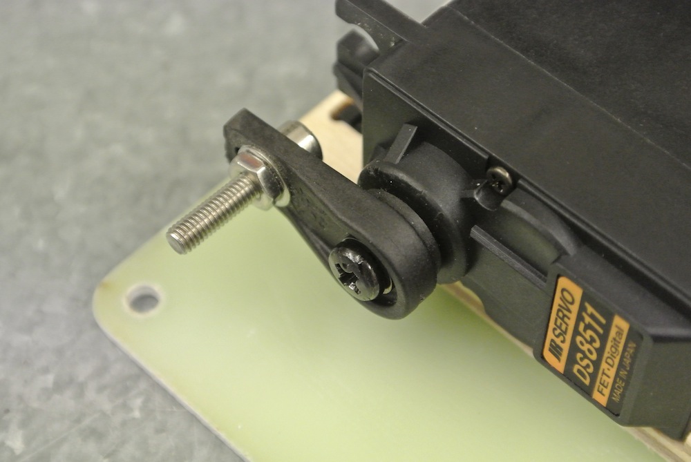
The flaps are driven via an internal linkage commonly seen on many larger jets, the horns a cnc'd carbon and are glued into slots pre-cut in the flap structure, I chose the ball link and bolted this through the two horns before preparing for gluing to make sure the gap was set right. I also angled the horns slightly towards the top surface as this makes for a better leverage on the flap seeing as its live hinged on the bottom.
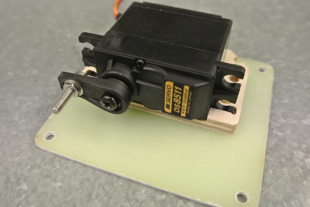
My dilemma with the flap servo was how best to mount it, I was keen to mount it to the top wing skin but felt this might not really be the right way as although the surface area being glued (using my wooden servo dock accessories) is large the skin is not really structural. Mounting to the servo cover which is a 1.6mm G10 plate would be better as the cover locates onto ply formers which surround the servo opening and provide the bolt holes to secure the cover. After some head scratching I decided to mount the servo on the cover, the more tricky part to this method is setting the correct location for the servo in respect of the linkage etc but a little juggling resulted in the location marked up.
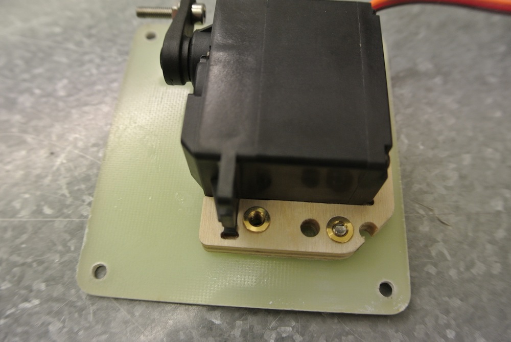
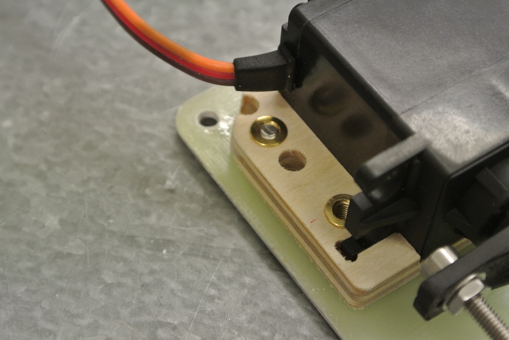
I did not have any more of the aluminium servo mounts left, 4 were supplied so will advise that 6 are included in the production kits, so used my servo dock which turned out to work well. It need the corners trimmed a little to avoid the corners of the servo hatch where the bolts went. I used two of the glue seep holes to insert small M3 blind nut inserts so the plate is held in place by bolts passing through the top of the cover, it meant no glue was needed which in the case of mounting servos is in my opinion a good move.
The two holes in the servo dock which normally take the servo security strap will be used as the 3rd and 4th fixing points and I have ordered some 30mm long bolts that will not only bolt the base of the servo dock to the servo cover but extend up and allow the security strap to be fixed as well holding the servo well in place.
The linkage can be attached to the servo arm easily before placing the cover in place and fixing it down with the 4 M3 bolts.
Servo is a JR8511 with a short 14mm centred arm. I used the 72mm long turnbuckles to make up the linkages which gave a nice overall length.
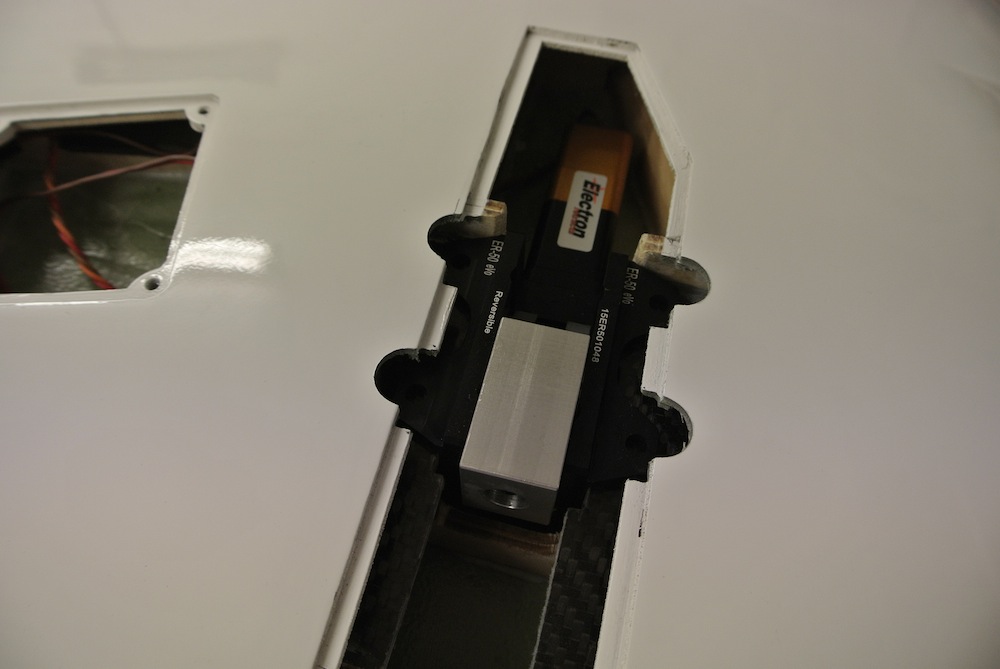
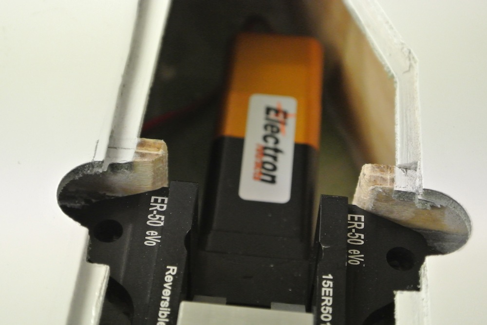
Electron Gear Modification.
Now the nose gear is almost done I tackled the main gear starting with one wing as the dummy....
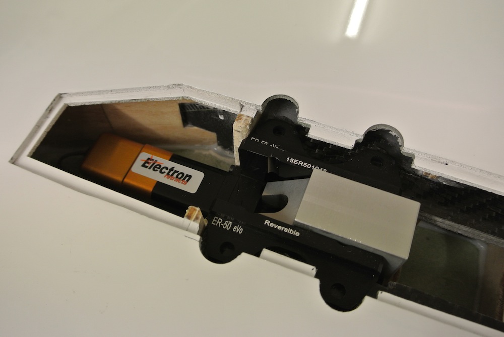
The rails fitted like in the nose need to be opened out, its only 4mm extra each side so marked the rails and sparked up the Proxxon with various carbide rotary attachments, once the rails were opened out the former under the rails needed some material removed as the Electrons are deeper than the pneumatic gear set. Again more surgery with abrasive tools.
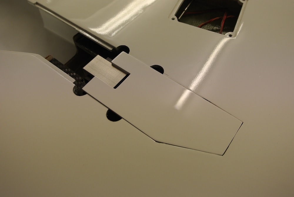
The fixing lugs on the Electrons are also naturally wider as a result of the wider retract unit, I could not find a way to slide the retract onto the rails so reluctantly sanded 4 semi-circular cut-outs in the skin to allow the lugs to pass through for fixing, I might just leave them or re-make the cover plate (which will need the slot opening out) to match the new opening + cut-outs.
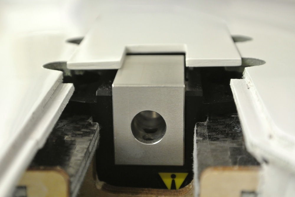
The Electron now sits nicely in the wing, below the skin so the leg covers should also fit.
Next job is fixing the final main leg length based on the retract position and the wheel well cut-out. Just for info the wheel wells are enclosed, I have added a picture of this as its a nice touch and makes for a cleaner look.

marcs