I still need to dust off that camera, but I have been working on the GP Super Stearman, I should add; at a snail's pace. I had my foot operated on almost seven weeks ago, which left me drugged and groggy for a week or two, and weak and slowly recovering ever since then, pushing a knee scooter around. Kind of like powering a 1.20 size model with a .46 -- NOT great. It's slow going, for sure.
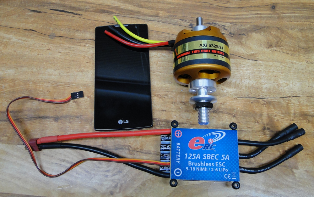
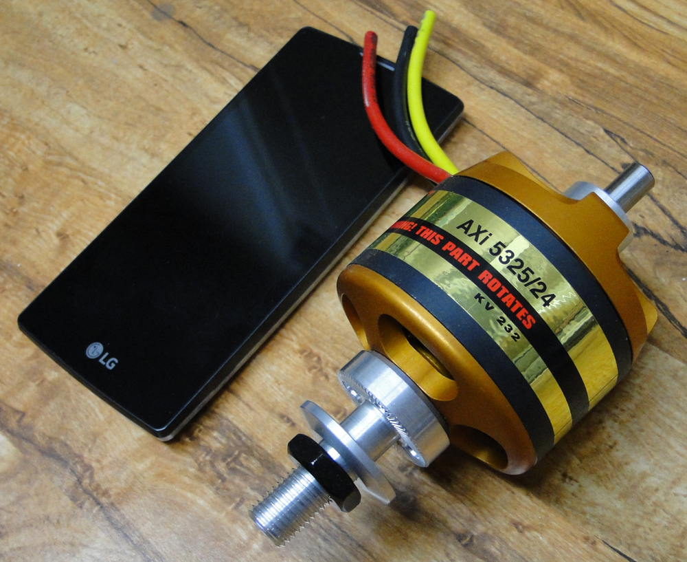
I assembled the JR ST126MG servos and worked on the fake radial engine. The fake radial is almost ready, but I'm still thinking about how to trim out the cooling holes for the electric motor. By the way, I DID go with the AXI 5325/24 electric motor, and I also went with a GP electric motor mount from Tower --the big one for the large motors. Turns out that was a lucky move. It has slots that match up EXACTLY with the stock T-nuts in the Super Stearman's firewall. I could claim it was all skill on my part, but I'm okay with just being lucky! Here's a photo of the motor and the speed control. To give you an idea of the size of this motor, I placed my full-size smartphone (LG Escape 2) next to it. After holding the little E-Flite 400 size motors between my thumb and index finger, this thing seems massive. It's really hard to just turn it over to the next magnet. On the speed control, the red and black wires you see are ten gauge wire to handle all the Amps. I bought 6mm bullet connectors for the wiring. Sorry, I forgot to write down where I bought them online. It was a place like Hobby King.
I took a HOT covering iron and stretched the covering on the whole plane. I did the same to all the control surfaces, and then I installed Robart pin hinges on all control surfaces. You may recall that the Super Stearman comes stock with CA hinges, which I equate to installing an expiration date on your plane. I went with the Robart standard size pin hinges this time. Last time I went with the large pins, and they worked out okay, but I ran into some problems with the fitting of the large pins. The standard size pins work much better on this model, though I increased the number of pin hinges I used on each surface by at least one or two.
Before moving ahead, I took this time while the control surfaces were loose, and attached my servo horns. It's always a royal pain to install servo horns after the control surfaces are attached to their wings/stabilizers/fins, etc. On the elevators, I used DuBro large scale double horns to use with the large ball links for smooth motion without any binding. I'll be using Central Hobbies carbon fiber linkage tubes with titanium ends. My preferred ends are the 3/16" X 4-40, attached with the JB Weld, which I've come to prefer over 30-minute epoxy, though I never had a single failure with the epoxy. I just like the consistency and ease of working with the JB Weld, and the pros all swear by the JB Weld. Cleans up easily too, with a small bit of paper towel. Here's a photo of the aileron linkage. The control horn shown here is a Robart ball-link control horn.

With control horns and Inter-aileron horns in place (I'm using the two-servo configuration on my ailerons), I moved on to attaching the elevators to the horizontal stabilizer with the pin hinges, and attaching the ailerons to all four wing panels in the same fashion. I laminated the bits of lite-ply provided with the kit to create the wing braces, and when those were dry I joined the lower wing halves using 30-minute epoxy. Using the strings they ran through the wings, I mounted my servos in the lower wing, and added servo extension wires. Next, I tossed the provided nylon wing pins into the trash, and installed 5/16" Oak dowels in the wing's leading edge. I'm sure the nylon pins would work just fine; I was just being myself!!
I struggle constantly to set up the perfect linkage, one that won't rattle or bind, and I've come very close several times, but here I finally came up with a combo that fills the bill. On my servo, I use a JR gold servo arm with 4-40 threaded holes, and I attach DuBro or Sullivan heavy duty Ball Link connectors to the arm. I already mentioned the Central Hobbies Titanium ends and carbon fiber rods, and finally at the aileron end I installed Robart 5/8" ball-link control horns (Sorry I wrote DuBro before. I used those on the elevators). The result is an assembly that's perhaps a little pricier than I'd like, but the big payoff here is that I'm completely confident these linkages will hold, come what may. Nothing worse than a linkage that comes apart on a hard-working bipe or 3D control surface during a grueling workout.
Things are off to a good start here, and I'm finally feeling healthy enough to spend more time at my building table.
Next time I'll tell you about my decision on which linkage configurations I'm using for the tail surfaces, and why.
Jim