Dusted off my soldering skills today & did some electrical work.
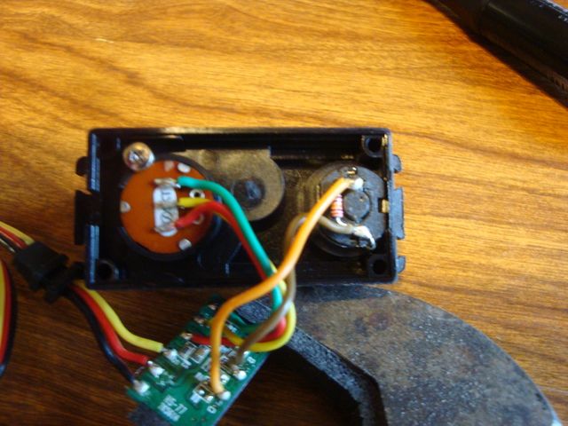
1st off I needed to reverse one of the HS-77BB servos for use on the starboard flap. I didn't want to use a reversing "Y" harness so I Googled it I found a YouTube video that showed a Hitec servo being reversed internally.
I used a fine tip soldering iron & it was quite easy. All that needs to be done is swap the green & red (outside) leads on the potentiometer (left) and the yellow tan leads on the motor (right)
Here is the video, but this guy used a large soldering gun & I would not have attempted the job with such an unwieldy tip.
https://www.youtube.com/watch?v=EK_FdRTenl0
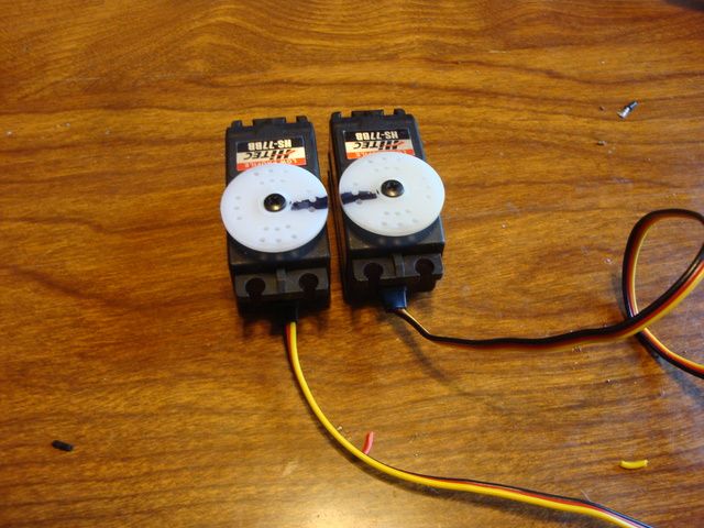
Here is the standard HS-77BB servo along side of the reversed at center. (note the black lines)
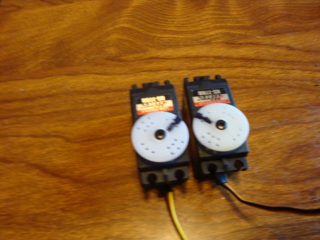
Here they are when the flaps are deployed W/the Tx.
This is a 15 minute job & I would never use a reversing "Y" harness since it is so easy to do if you have a fine tip soldering iron & some decent soldering skills..
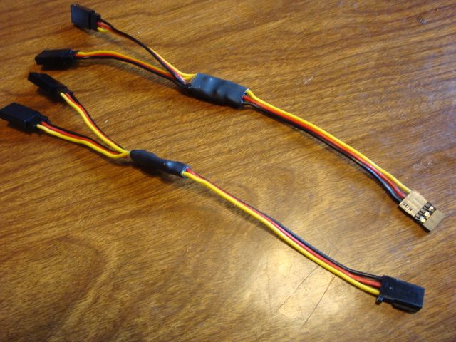
Next, I tackled fabricating my own "Y" harnesses.
I used the "PC board method". I picked up a small sheet of 1/6" copper clad PC board & "PCB Etchant Solution" @ Radio Shack.
I cut a 4" x 3/8" strip with my motorized miter box. After dressing up the saw cut edge on the disc sander I drew a 1/8" stripe down the center of one side W/a black permanent marker. On the back side I drew 1/8" stripes down either side, leaving a 1/8" of bare copper in the center. I placed it in a shallow plastic tray in 1/4" of Etchant Solution. It took a little longer that the 20 minutes in the directions most likely due to the cool temperature of the solution.
After about 45 minutes I was left with what I needed. I cut pieces about 1/2" long.
1st I soldered the red leads to the side W/the copper stripe down the center.
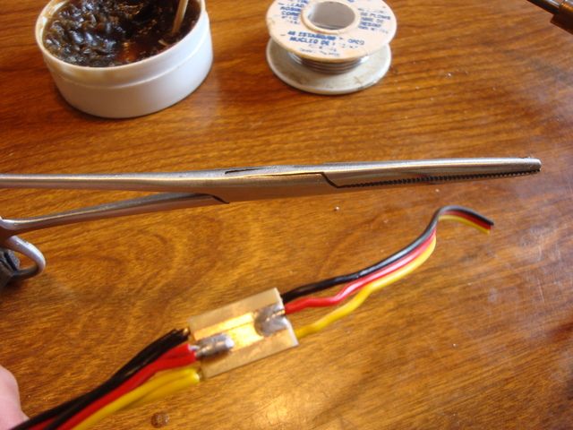
On the flip side I soldered the yellow & black leads to the stripes on either edge.
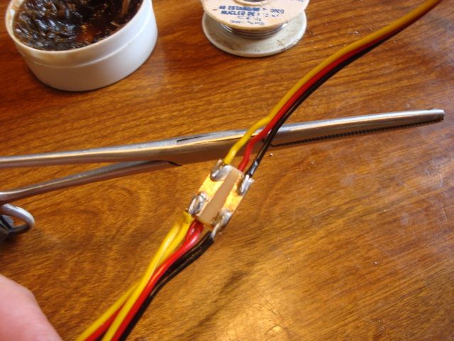
After applying a bit of electronics grade silicone to each end of the boards, I cut a piece of shrink wrap & heat shrunk it to insulate & protect the board.
When I made the extensions for the flap & aileron servos, I used Futaba "J" & Hitec/JR ends respectively. This will make it impossible to get the leads mixed up on assembly.
I fabricated the "Y" harness on top W/Hitec/JR connectors, the one on the bottom Futaba "J" connectors. The Rx will accept either.
 HERE IS A THREAD
 that I found here on RCG about this method.
Right now, the port wing is complete except for the trim/pin striping on the top and the push-rods for the flaps/ailerons. I am opting to make them from 2-56 rod since they are so short. The ones that came with the ARF are way oversize. I like to use a "Z" bend on the servo end to allow mechanical differential to be built into the ailerons. The "Z" bend allow the servo arm to rotate much farther forward than a clevis. I orient "center" position of the servo at 45 degrees forward to accomplish differential.
I'll tackle the starboard wing tomorrow & hope to have it completed.