Thanks for continued interest in this thread.
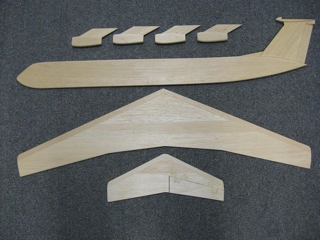
The reason for my opening post is I want to try to complete a modeler's project he gave me before he died. Its a profile Lockheed C-141 Starlifter and may be using Jim Mayfield's design idea. I'm not a trained engineer, so I'm trying to gain as much information as possible to tackle the task. My primary interest is R/C, however, I dabble in C/L on occasion. C/L somehow falls into the progression of interest in aviation for my makeup. Maybe he abandoned it because he thought it wouldn't work well but I want to give it a go. Like someone I know once said - "I know just enough to get me into trouble" so here I am and I appreciate all the help I can get...
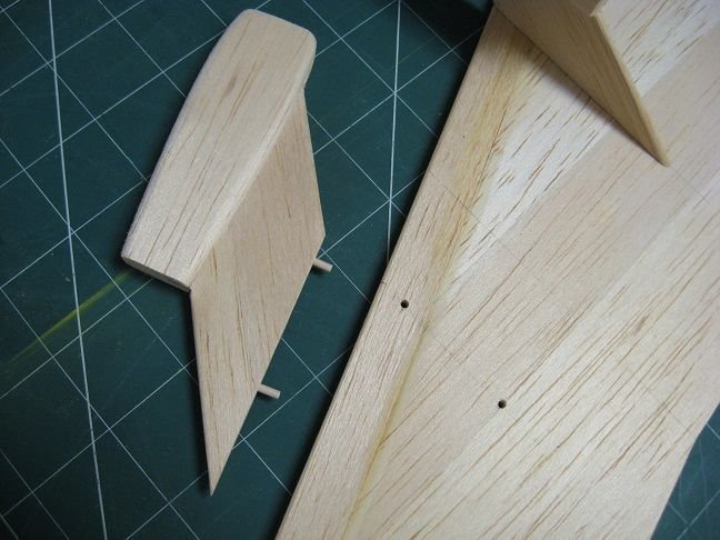
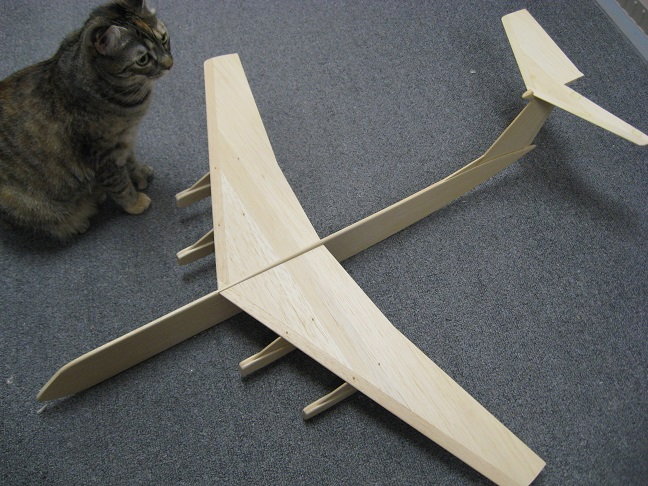
I've started work on it. Located fake engine nacelles to the best of my ability and pinned same to bolster attachment to wing. Followed preliminary wing cut-out noted in fuse to locate wing for (intended?) angle of incidence. Engine to be located between fuse and nacelle #3 - thrust-line normal to LE Like Jim Mayfield's Charger. Thinking vectored thrust here - more line tension than forward motion... Cat included in pic as means of size reference. To be .049 powered. Not sure if elevator should be inboard or outboard - shown inboard here.