I am moving a bit backwards into the Demon genesis story.
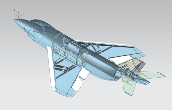
Here are some more CAD rendering from Siemens NX12 and some explanations.
The plane will be very easy to ship and transport.
The fuselage will be split in 3 parts. Wings, fin, stabilizers will be removable.
The fuselage will break into: nose section, cut at the main panel line in front of the wing, middle section excluding the beaver tail, and rear section ( essentially the beaverr tail itself ). The rear section will split just at the tailpipe.
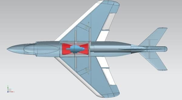
The wing will have two 30 mm carbon tubes. The rear main tube will be a single 3 foot piece ( that passes just below the thrust tube ). The carbon sleeve will be ceramic coated and aluminum shielded to avoid heat transfer.
The front wing tube will stop at the engine bypass section.
The engine and fuel tank will be located exactly on the CG.
The plane is designed for a 120-140 class powerplant and is designed for 15 g load at 16 kgs takeoff weight.
Tank size will be 5 liters. A smaller/ lighter plasma bag option will be available for 13.5 kg class scale competition.
The flight controls are:
2 stabilizers, 1 rudder, 2 slats, 2 flaps, 2 ailerons, 1 steering. or 10 servos.
The flaps, ailerons and slats will be live hinged, like our Crusader, with our Gorillahinge system ( a polymer infused fabric that sustains 200 kg.cm of tear force ). They will include an aerodynamic seal surface, like the Crusader.
All control links will be hidden.
The tail section ( beaver tail ) will be removable and include the fin support, stabilizer support and fin/ stabilizers servos.
A large hatch will be located at the top of the beaver tail to give access to the 3 servos.
The stabilizer and rudder controls links will be hidden.
The rudder will be controlled with a torque rod system that slides in a slot at the bottom of the surface.

The tail section will connect to the center section with 4 screws and 3 carbon tubes to ensure perfect rigidity and pitch/ yaw precision.
Al large bearing system will be set this section, between two carbon fiber bulkhead.
The two stabilizer servos will be relatively close to the shafts.
The rudder servo will located at the center, in front of the stabilizer servos.

The stabilizer shafts will be made of Alcoa Al 2028 12 mm rods. The will have a key system to permanently lock the arms.
The control arms will be keyed/ clamped with a M3 socket head screw.
The shafts will be supported by two ultra high tolerance 12 mm needle bearings each. These sustain 500 lbs each.
The bearing block is a billet milled Al 7075 unit that is sandwiched between two carbon fiber bulkheads.
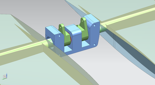
This assembly is exactly the same as for our 1/7 scale Crusader and has proven to be absolutely bullet proof.