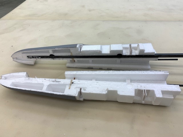
Splitting the rear fuse
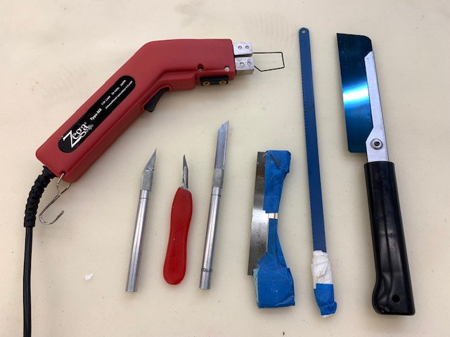
Foam cutting tools used
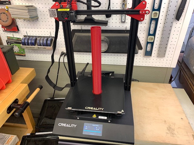
I asked Keith to send me a file to 3D print a 52mm sanding drum mandrel. I anticipated the need to sand the aft fuse to create the channel for the turbine pipe. I printed it from PLA and it was very useful for several tasks in the build.
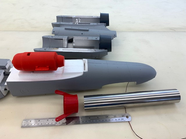
Initial concept of turbine placement
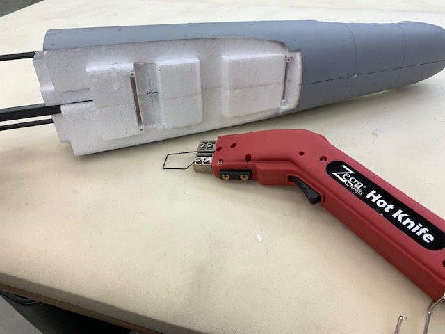
Started using hot wire cutter to slice off foam parts but then decided to split the aft fuse in half
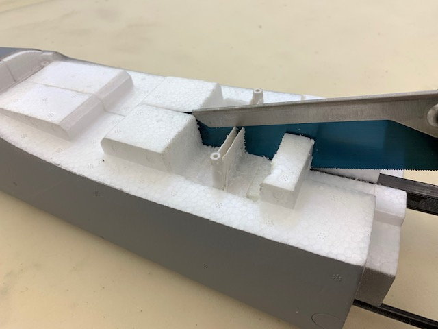
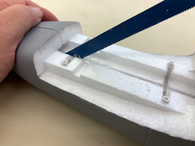
Razor saw initially used to cut through FW plastic engine pod mounts
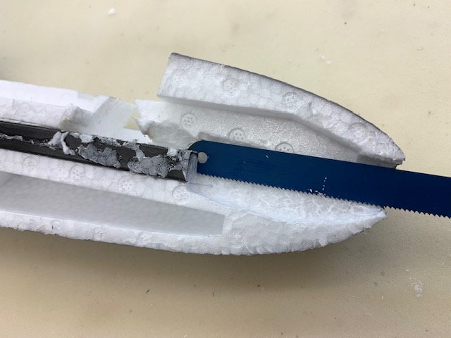
Switched to hack saw blade for deeper cuts
Cutting aft engine pod mount in half
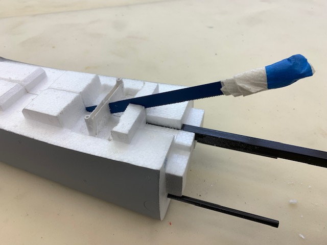
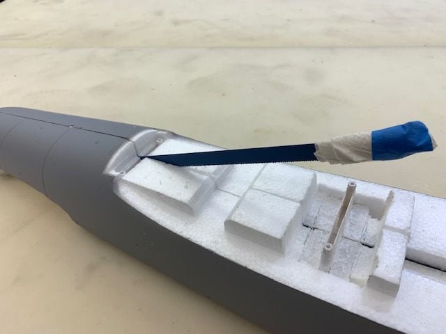
Cutting forward plastic stab mounts
Cutting aft stab mount
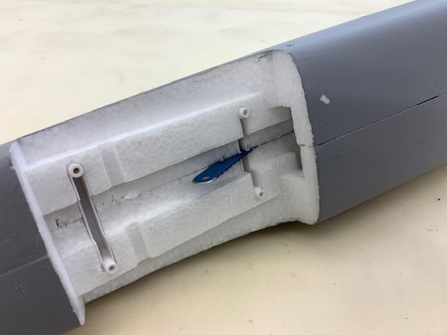
Aft fuse split open showing carbon square tube backbone. I was surprised to see how far back it went.
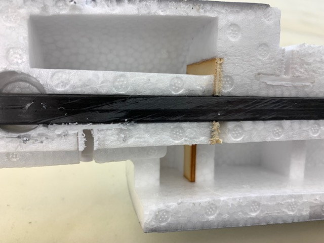
Hidden ply former to hold the square carbon tube in place
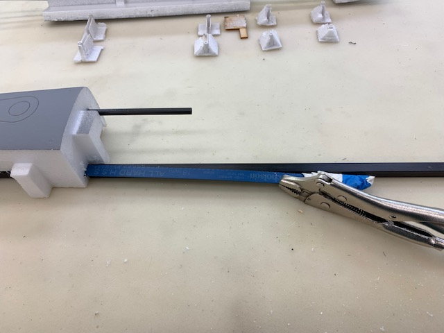
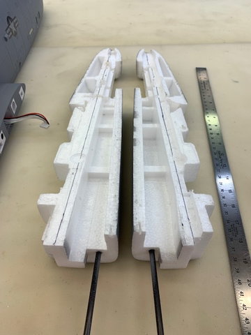
Hack saw blade in vice grips to cut out the square tube
Slicing out the aft end of the tube
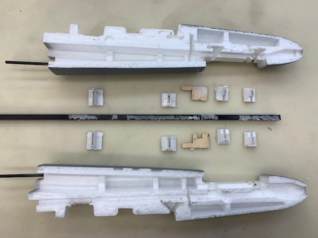
Plastic and wood parts removed from the aft fuse. This where I began to wonder if this idea was going to work since there was not much foam in the rear fuse
I drew in my planned thrust lines from the center of the rear tail cone parallel to the carbon tube. As it turned out the planned thrust line was the top side of the carbon tube slot and closely aligned with a fuse panel line just above the main wing chord that went all the way to the nose. I figured since the new turbine thurst line was nearly at the wing line this "zero degree" thrust line would probably be OK. Like all the other foamy conversions I've done its all "TLAR" anyway.