Well progress has been made in a few areas.
First with the axle bearings.
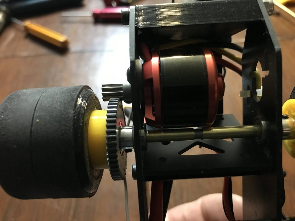
I used a larger bearing and a sleeve it to fit my axle.
Then the motor I was using was getting very hot so I went looking for another motor.
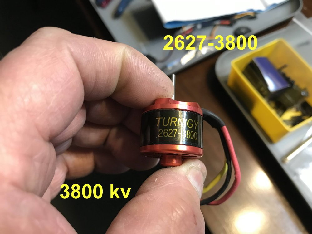
As it turns out I had some 3800kv motors so I bolted one of them in the car and used the ESC I had used on it in the passed.
It has a brake feature but it is either ON or OFF. So I turned the brake OFF. Mind you this motor and ESC are aircraft type but I had to start somewhere and really glad I did. From the test runs so far I am guessing I would need about a 1500KV motor for this project.
Since I am using a DX5R radio I have a lot I can do in the way of adjustments. So I set it up and have it running with no brake. (at the moment anyway)
I ran some hot laps today and made a few changes to the front end. Mainly to tighten it up. My first setup used Z bends which stress the holes when being installed and this can cause play in the steering.
So, here comes one of my race secrets for you. The secrete is in the picture and it really does work if you set it up right.
First you will need a few balloons.

Cur the ends off of them where shown.
If you want to stick with Z bends then here is how I set them up. Notice that each spindle is being pulled into the servo horn. This means the spindles do not move around as the car is moving forward.
And then there is another way and here it is.
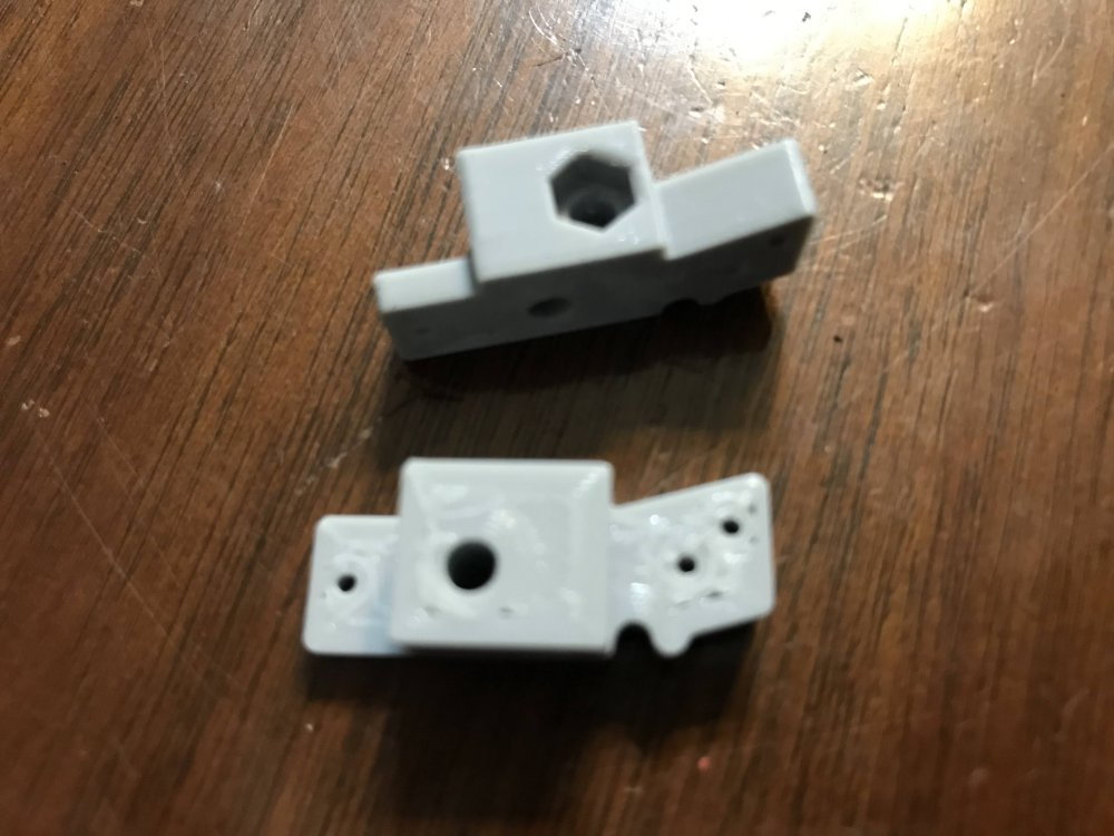
To keep from stressing the linkage holes I us only 90 degree bends. I also redesigned my spindles so they hold the balloon rubber and the material is thicker where the linkage connects to it.
Stay with me here because you might be amazed at how simple this system is and if you try it you may be even more amazed at how little play there is in the steering when it is done right.
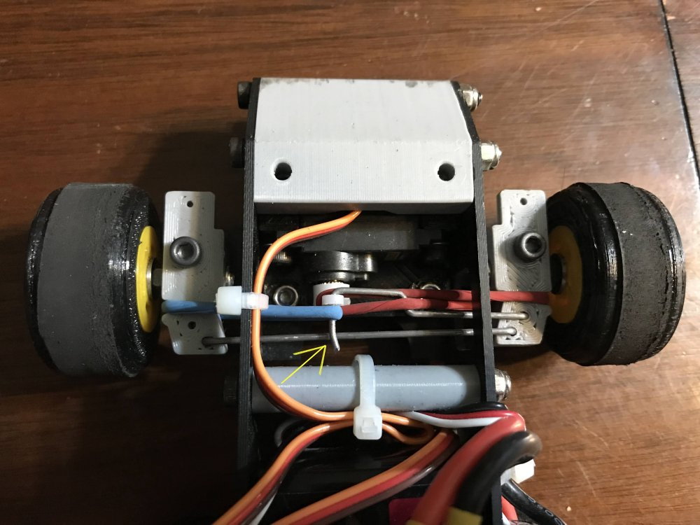
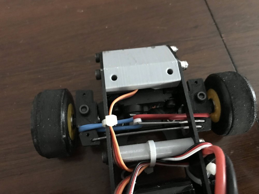
So here the system is installed. There is one Z bend and it is only to offset the servo linkage so it can be run straight over to the spindle. Notice how the balloon tips are installed.
Notice the red balloon end is just under the linkage wire and around the servo horn. Also notice the slight bend that can be seen in the wire that went through the servo horn.
This slight bend keeps the blue balloon end from sliding off the linkage. It also helps if the servo is placed so that the pressure on the balloon ends is always pulling them into the servo horn as shown here.
Notice the red balloon end and how it crosses over the Z bend in the servo linkage. This is what keeps the 90 degree bend from coming out of the spindle.
Notice how the chassis has a hole for the linkage to pass through. This hole is just tall enough for the linkage to go under but not so tall that it allows the 90 degree bends to lift out of the spindles.
As you can see it is a very simple setup and it gets rid of almost all the play in a linkage setup. Keep in mind that as a car rolls forward all the forces are pushing the back of each tire inward. Because
the balloon ends are pulling the rear of the tires inward already there is no play in the steering. Even on the bench you can feel a big difference in steering play once you install the balloon ends as shown here.
That is all I have at the moment.