Originally Posted by
Glowgeek
Possibly to help control oil pooling?
You hit the jackpot, Lonnie!
Originally Posted by
Cat 1
Bert, Can you explain the function of the holes ? Is the outlet of this elbow in the centre of its distribution to the "intake tubes"?
Of course...

Have I ever had a lack of words?
On the ASP, the intake system consists of a central intake hole, and a set of spiral shaped channels. Looks like this:

Assumption on my side, but I think this is done to prevent that the lower cylinders flood with oil/fuel at standstill: there is not one single intake that has a straight downward path, so gravity cannot do its dasterdly deed,
The fuel/air mixture enters in the brass ring, which has 5 holes drilled into it.
On the outside, the carb is fitted with a 90 degree elbow, and oriented such that when the engine is mounted according instructions, the intake mouth points down.
Again an assumption on my side, but I think this also is done to prevent any fuel possibly syphoning, to run out, instead of into the engine flooding it.
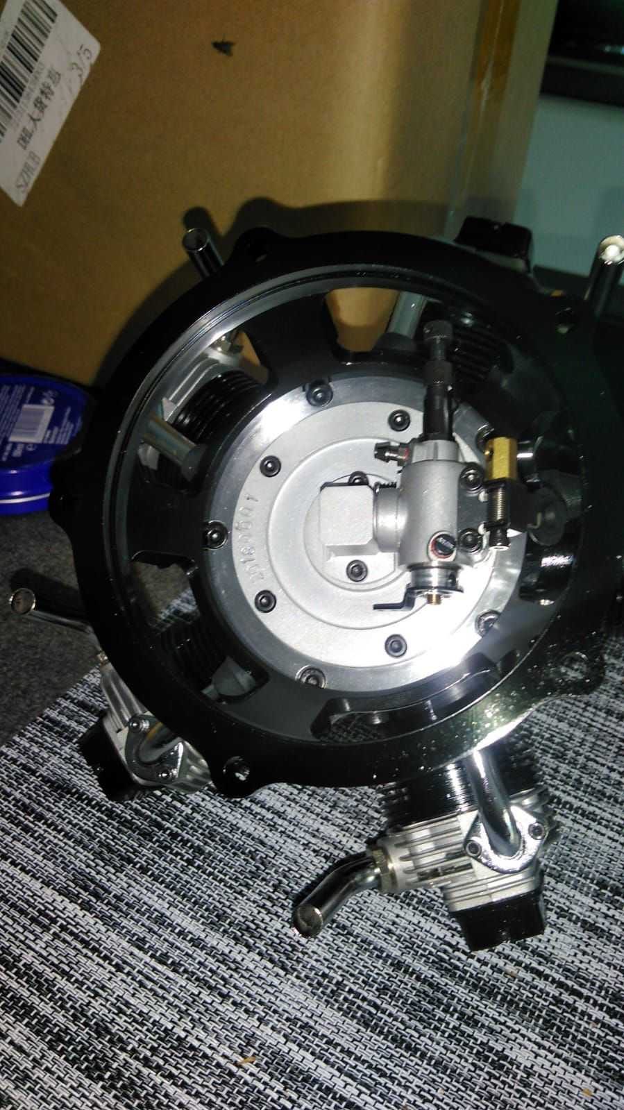 The engine is pictured here tilted roughly 30 degrees counterclockwise. In manual-prescribed mounting orientation (cyl 1 vertical upwards), the carb is below horizontal by 54 degrees
Now this elbow, and the brass ring in the first pic, THEY are the problem: the fuel/oil/air mixture directly behind the spraybar is not yet a homogeneous mix: it's air, vapour and droplets.
When that mixture has to pass the 90 degree bend, inertial forces separate this mix, air/vapour follows the change of direction but the liquid ends up at the wall opposite of where the carb is.
So that liquid does not enter the brass ring in the middle, but at the circumference, favouring 1 or 2 cylinders over the rest, And because the carb is a normal glow carb, with a laterally moving throttle barrel, the throttle position affects which cylinders exactly are favoured, because as the FT160 demonstrated, the amount of throttle opening affects WHERE exactly that liquid ends up at the wall.
What do the three tiny holes do?
When the engine is running, there is intake vacuum, IN that elbow. So air will rush in through these three holes. These holes are by the way, drilled under an approximate angle of 45 degrees, they are NOT perpendicular to the intake bore. They are also drilled parallel, not radial to the centreline of the bore.
Now, mixture comes into the elbow, passes the 90 degree direction change, and the liquid fuel/oil ends up at the wall of the bore. when that fluid passes the three bores, the inrushing air blasts that liquid back into "suspension" in the airflow. Turbulence, velocity and kinetic energy do the rest.
It is not perfect, but WAY better than what it was from the factory.
That is how it works.
MAIN reason for taking this route was that I could do this in literally 10 minutes and a 1 dollar drillbit, as opposed to sourcing large barstock Aluminium and spending days behind the lathe (I can handle myself, but am far from skilled, so it would take me ages).
But thinking about it a bit more, I arrived at a few conclusions that make me feel, the expensive commercially availlable mods are not all that desirable.
To me, the downsides of a "negative crankase pressure modification" would be:
-Oil lubricates better than "fuel dilluted oil", Although this has in other engines never presented a significant problem, it remains a fact that a negative pressure crankcase means the crankshaft and rods are lubricated with diluted oil instead of undiluted oil. Personal preference.
-Radials do not, like 2-strokes (and most fourstrokes) have a labyrinth at the crankshaft, meaning that the
entire functioning of the engine becomes dependent on the quality of the forward crankshaft seal.
This splits in two, IMHO rather nasty consequences:
-If the seal starts leaking, but not yet enough to disturb normal operation, the air ingress in the front of the engine, will scavenge lubrication AWAY FROM the cam drums and associated gears. So there is a real risk of accelerated valve train wear while it will not be immediately obvious to an operator, what causes this accelerated wear.
-progressing deterioration of this seal, will cause inconsistent adjustments, again, without its cause being immediately obvious.
-A full faillure of this seal will disrupt engine operation, period.
The big deterrent for me is, replacing this forward crankshaftseal (big words for "bearing replacement"
) requires a FULL dismantling of the engine, And there are assemblies in a radial that are sensitive and pose a certain risk when dismantling: A :censored: crankshaft seal replacement should NEVER require that kind of risk.
The literal only thing that could possibly go wrong with my solution is a clogging of the holes, and that can very easily be fixed without even taking the engine off the firewall... It has zero effect on the mechanical properties of the engine at all.