So Chris was taking a channel, doing some math with the channel value, and adding it to the result of the engine rpm after he applies an exponential curve in the controller to the rpm.
First step is figuring out how to best drive the motor and that was a simple transistor switch that I put a pwm signal to. I'm going to add a capacitor across the motor to see it it performs better today.
I'd like to start reading s.bus since we're using 2 channels for the controller. Sbus is inverted serial so I need a transistor to inVert the s.bus so hopefully I can read it with the serial port on pin 7 of the Arduino (currently not used by the Xiao controller.)
i think I also want to buffer the rpm signal to protect the rpm pin.
Those plus the 2 drivers for the solenoid and air pump makes 4 transistors.
Rather than r separate transistors with their 4 separate base resistors plus series resistors....
I just finished this clock...
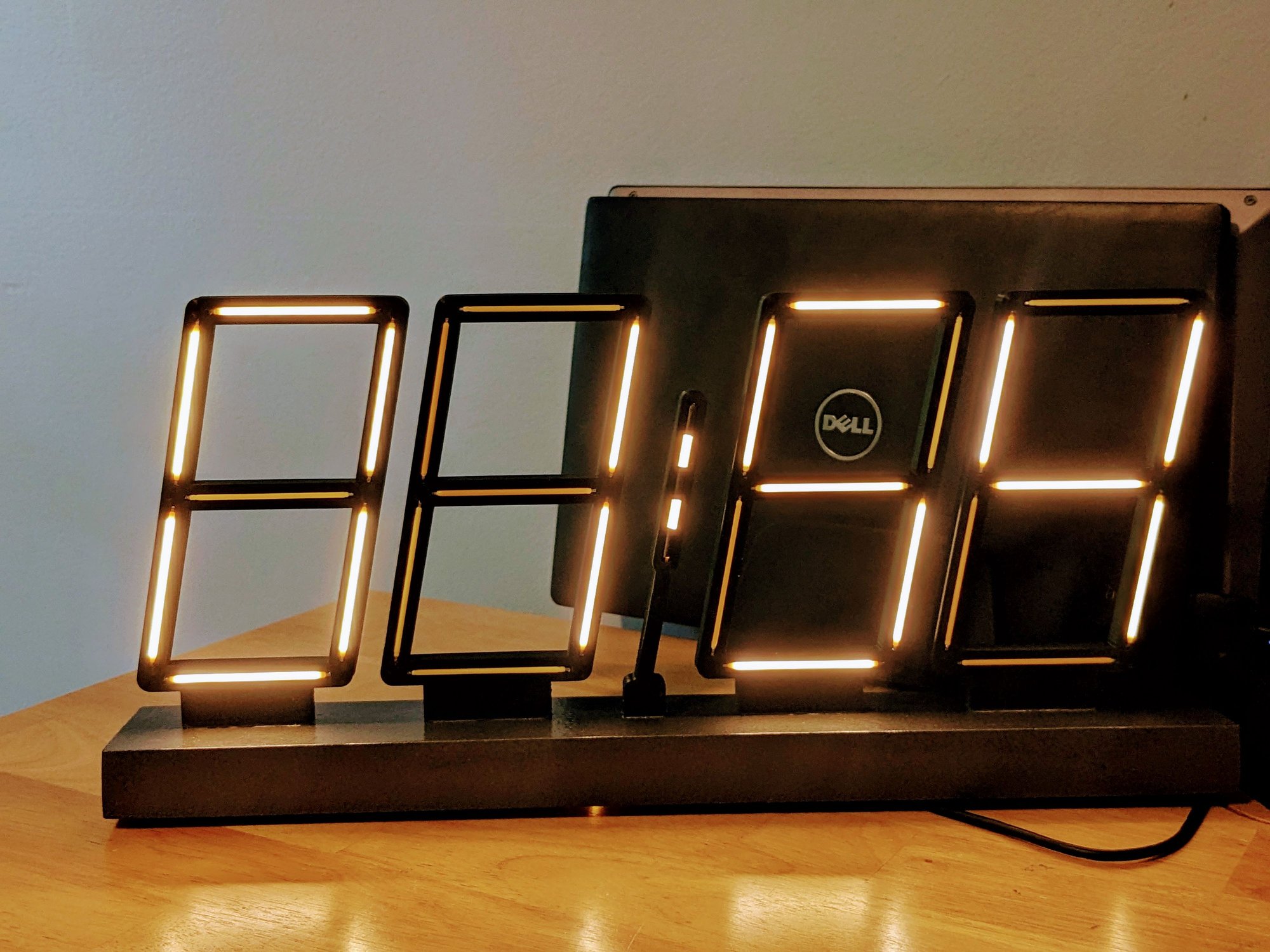
with digit driver's using uln2003a chips which are 7 Darlington transistor pairs with base resistors all wired up in a 16 pin dip package. It'll work great with 3 extra Darlington pairs unused (for now). This should make wiring very easy.
I'm off to breadboard the circuit and write some code....