Hi All,
Well here are the build notes that I said I would post. I wasn’t sure where to post this… but since it is powered by gasoline (well, camping fuel) and it’s stretched out bigger than 1/10th now… I figure I would post it here in the large scale section.
First off… here are the videos of the Maxx Gasser running. (for people that didn’t see them in my other post)
[link=http://www.rcpics.net/view_single.php?medid=54663]The Maxx Gasser running[/link]
[link=http://www.rcpics.net/view_single.php?medid=54664]Pit Stop and restart[/link]
So, let’s get on with it…
OK… this project started because a friend I fly RC helis with hated to go out to the flying field and have it be too wind to fly. So… he talked me into putting a truck together so we would have something to do until the wind died down. This project went from an idea in my head, to a driving truck in two weeks. Then, one week later, it got a new engine. Oh… by no means is this a complete step by step set of “Instructions” on how to build one of these. But it should give anyone an idea of what it will take to do the conversion. But, if someone else is thinking about doing this conversion… you should chose an engine that has a clutch on one side, (mine is in the black housing) and the pullstarter on the other. This type of engine has a “Full” crankshaft which is stronger than the typical home use weed eaters. The ideal engine should be small, and compact with a good solid clutch built into it. The John Deer and Echo engines are perfect candidates. Oh… and I wouldn’t go any bigger than 23cc’s. if you go bigger than that… you may have a hard time getting the body to fit… you will kill the plastic parts quickly… and, you will have a truck that won’t ever keep it’s front tires on the ground!! OK… that sounds cool… but when you are driving around, or racing with your buddies, it can get annoying.
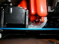
The original plan was to fit the engine without having to stretch the chassis. But, the original engine was larger than the John Deere engine that I’m using now, and I wasn’t able to move the transmission as far forward as I hoped I could because the steering bell cranks are in the way. So to simplify things… I mounted the transmission just behind the steering assembly (one less thing to mod) and added 1.5 inches to the length of the chassis. Adding this amount made it the perfect length for any of the 1/8th scale truck bodies, including the LST, and the Associated monster GT bodies. The lengthening was done by cutting the underbracing in the middle of the 8 bolts that hold them to the chassis pan. Then a simple aluminum channel was added to each side so that the pan would not flex. (the engine mounts help with this also)
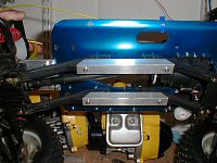
The extra length was added to the pan by simply making an extension out of .125” aluminum plate. When the chassis is bolted back together, the front bracing will bolt up to the original holes, and the rear will need new holes drilled in the pan.

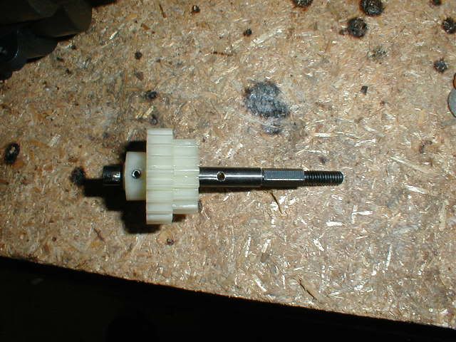
To get a few extra inches of space… the transmission is bolted in the chassis backwards. But since the input shaft will be on the wrong side now… you need to fix that. This is done by drilling threw the plastic trany housing on the rear bearing, and flipping the input shaft around. But… you will now have to flip the first drive gear around on the shaft. The do this, pull the pin out of the gear, pull the gear off the shaft, line up the gear the correct way on the shaft, mark the shaft for where the pin should be, then drill a new pin hole.

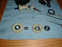
You should now have a backwards running trany. BUT !!!... you need to see what way your engine spins. IF your engine spins COUNTER CLOCK WISE looking at it from the front… your transmission is done. IF it spins CLOCK WISE from the front… you need to press out your one way bearing from your two speed section, and flip it around. AND you will also have to flip over your shifting ring, otherwise you will be going no where and not shifting. (my first engine spun CW, and my new engine spins CCW so I know this works) Also, if this is done right, the 2 speed section will still work. Just don't have it shift at too high of an RPM. the heavy flywheel won't slow down for plastc parts. (get it?... BOOM)
Once your trny is done… you will need to mount it. This is done by cutting the pan and drilling new holes. My trany is mounted slightly to the right side of the truck. This helps line it up better with the engine, and will give you a good strong mounting point. (if you do this conversion you will see why) The trany is also mounted on a slight angle. I did this by adding some washers. If you want to do it a different way… fine. You may not have to depending on your engine. Oh… the coupler on the input of my trany is a transmission output yoke. You can use what you like to couple the engine to the trans.
Now… with the chassis being longer, and the trany moved to the front of the truck… you will need a longer driveshaft. I made mine out of two rear axle shafts. I put the inter spline shafts on both the trans and the differential. Then I used a cut off section of the outer spline shaft and simply slid it over the middle. It seems to be holding up fine. Oh… I used a bit of electrical tape on either end of the center section to hold it into place. (the tape has no load on it so it’s ok) Also… since the trnay and rear diff are fixed… it doesn’t have to get longer and shorter as the truck runs. So, this is a simple fix with a stock part that can be bought cheap if you need to replace it.

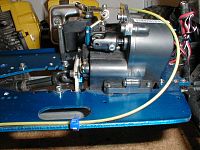
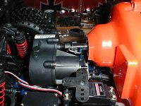
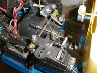
Mounting the engine. Hummm….. OK… there is no good way to tell you how to do it other than to say it needs to be very rigid and strong. If you can grab the engine and move it at all… it will get torn from the truck on the first flip. My mounts are extruded 3/16” aluminum. Here’s pics from both of my engines so you can get an idea of what I did. Also, take time to line up the engine. This will cut down on wear and tare.


OK… hooking the engine to the trany. I went direct drive on mine. First of all, this gets rid of the exposed gear. And because this type of engine only spins up to about 10,000 RPM’s… you don’t need the other reduction. Here again… no easy way to tell you how to do it, so here are some pics. I did however, leave some slop in the holes around the bolts that do the coupleing. This alows the engine to be slightly misaligned and not bind while its spinning.
OK… the last thing about the drive train. Since the trany is now mounted backwards… AND if you have a CCW running engine… if you try to drive your truck, it will only run in reverse!! But, the solution to this is very easy. The differentials in this truck are symmetrical. So, all you have to do is pull the rear diff housing out of the truck, and flip it upside-down. That’s it… simple. Bolt it back together and your done. (if you have a CW running engine, you won’t have to do this)
OK… the rest is just rigging. And… if you’ve come this far, I shouldn’t have to tell you how to hook up the breaks, run a throttle cable, or mount a servo. Besides, there are enough pics to let you see what I did.
If you have anymore questions, please post them here.