We have been discussing the new .40-size GP Reactor in [link=http://www.rcuniverse.com/forum/m_4455981/tm.htm]this thread[/link], however, I couldn’t seem to find a dedicated build thread for this plane, so I created this one. I will be taking lots of photos so that anyone interested can get an up-close-and-personal look at this new offering.
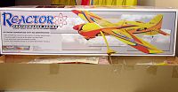
Here is the box. It was well packaged and nothing was damaged.
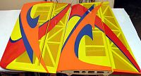
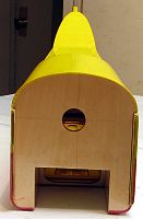
I should note that I’m just getting back into the hobby after a break of several years. The advances in ARF quality are simply astounding to me. This plane will be the 5th arf I’ve assembled over the last few months and, like the four before it, it’s beautiful. I could go on and on about the attention to detail and so forth, but I’ll let the pictures speak for me. Here are the tail feathers, cowl and landing gear.
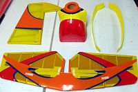
In these two pics, I tried to show that the stab/elevator and rudder are airfoiled. This may be old news to some of you, but to me, this is very impressive on a 40-size bird.
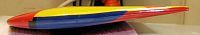
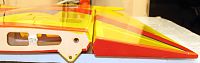
Here are the wings and ailerons. The covering is very well done and nice and tight. I will end up going over it just for my own peace of mind, but I suspect it would do just fine as it comes out of the box.
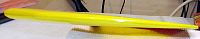
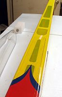
Here is the wing root of the right wing panel. You can see the aileron is also nicely tapered.
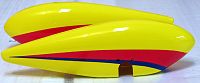
Here are the wheel pants. They, along with the cowl, are fiberglass and the paint seems to be applied very nicely. I know very little about paint as I’ve always been a iron-on kinda guy, but these parts really look great to my novice eyes.

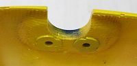
Here is a close-up of the mounting points inside the pants. You can see a nice fat piece of ply inside there with two blind nuts already installed. You may also be able to tell that the ply has been glassed into place as well. Very nicely done.
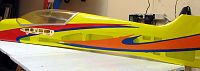
Here is a shot of the fuse from the side.
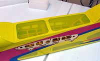
And here is a close-up of the canopy area.
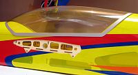
Here is the attachment point for the left wing panel.
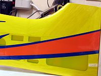
And here is the tail section. There are 3 servo cutouts on each side of the plane, but only half of them are used. The two upper ones are for the elevator halves, but the narrow fuse requires that they be staggered so the servos don’t interfere with one another. I was surprised to find that there is no provision for the use of a single elevator servo. I’m certain one would provide adequate muscle, however, I suspect the use of two helps eliminate the possibility of flexing between the halves were a joiner to be used. Oh, and only one of the two lower ones (not really visible in the picture) is used for the rudder.
Here is the firewall. You can see the thrust lines are offset to allow for right thrust.
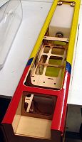
Here is the bottom of the fuse. There is a long narrow hatch that provides access to the radio compartment. There is a lip on the front end of the hatch, and it is held in place with 4 sets of magnets, which is very clean and hopefully, very secure.
Here is the inside of the radio compartment.
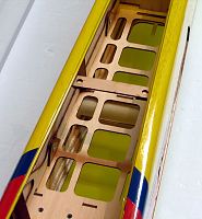
I’ll be powering this plane with a YS .63, so one of the first things I wanted to check was how much room there was in the radio compartment for the fuel tank. The pressurized and regulated fuel system of the YS allows the tank to placed virtually anywhere on the plane. Putting the tank on or near the CG means there will be minimal changes in trim as fuel is consumed. I was happy to see that the supplied fuel tank easily fits in the radio compartment. In this picture, it is centered over the wing tube.
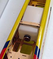
In this one, it is as far back as I could slide it. I can’t imagine anyone will want to install it there, but you could if you wanted to.
Well, that completes our walk-around tour of this plane.
I hope to actually get started on it within the next day or so. If anyone wants any specific pictures or information that is not readily apparent or available, I’ll be happy to do what I can to help.
Erik