Not sure if anyone is interested or if this is an old idea, but it's new to me.

I'm installing a YS .63 in a GP Reactor and came up with a slightly different way to route the necessary fuel and pressure lines. For anyone who has ever used a YS, you know that it's a closed fuel system. It makes use of a pressurized, regulated setup to deliver fuel to the carb from essentially anywhere on the plane. It allows you to place the tank farther away from the engine and still get reliable, consistent performance. Anyway, the typical installation makes use of T-fittings in the pressure and feed line, allowing you to bleed the pressure before refilling or draining the tank. Failure to relieve the pressure can result in a shower of glow fuel.
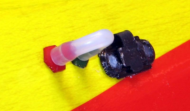
Anyway, the lines coming off these T-fittings usually are sealed with plugs commonly called "fuel dots" and are accessed through holes in the side of the fuse.
For my Reactor, I assembled the tank with a three-line option. In addition to the conventional vent and cluck line, an additional clunk line was installed. This second clunk line is a dedicated fill/drain line. That is, it's used to fill the tank and drain the tank at the end of the flying session. Instead of using dots to access both the pressure and feed line, I installed two Fourmost Bulkhead Fittings in the side of the fuse. One of these goes to the dedicated fill/drain line in the tank and the other goes to a T-fitting installed in the pressure line, downstream from the check valve. For the uninitiated, the check valve is what maintains the pressure in the tank. This pressure is provided by a regulator mounted on the engine. As you can see below, this plumbing eliminates one of the T’s from the system and provides for an uninterrupted feed line to the engine. Here is a diagram of how it all goes together.
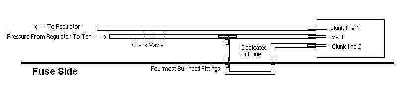
In practice, the two bulkhead fittings use a "jumper" piece of fuel line to join them together, effectively pressurizing the tank via both the vent line and the fill/drain line. At the end of a flight, one simply pinches the jumper line shut and pulls it off the bulkhead fitting tapped into the pressure line. This vents the pressure in the tank without spraying fuel everywhere. Then, you can plug your fuel jug feed line into the jumper line and refuel or defuel your plane. On the plane, the actal fittings are much closer together than depicted in the diagram. The jumper line is only about 1.5 inches long.
To me, this setup seems easier than dots because there are no plugs to remove (and lose!), no lines to feed through the fuse side and only one connection to handle on the plane. On the negative side, the dots are less conspicuous and easier to hide. In the end, I suppose we have to go with whatever setup best suits our needs. I hope I was able to describe all this in adequate detail.
If not, or if I've made some crucial error, please speak up and let me know.
Erik