wow, a different experience. not many have a chance at getting or setting a timing system, there is some information, but not tons of it.
the first thing i must mention is setting up the sensors.
the start line has two sensors 2 Inches apart. they require one infrared light at the start line to trigger the sensor.
(like this)
I IIIII
(2 inches in between)
-IIII
the single IR light beam is placed on the start line on at the outer edges of the track, it will trigger both sensors. the first sensor and start line is called "stage", and the sensor before the line is called "prestage".
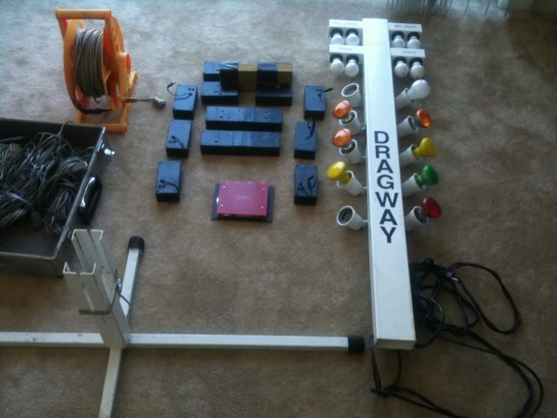
i went ahead and taped a 2x4 in between the sensor blocks to help keep the alignment and space perfectly (look for the wood 2x4 in the first pic). it requires 4 sensors and 2 beams.
the sensor is pictured below the left and IR beam on right.

it uses a wire harness made with 4 separate telephone lines. (the wire set in the briefcase). i connect these to each phone jack on each sensor. the serial port end i plug into a red reciever box with the company logo. this box has the serial ports for all the sensors, computer, and lights.

next, i measure 122' and set the first "speedtrap" sensor. at 132" i set the "finish" line sensor.
like this...
I-IIII-I
(ten feet in between)
I-IIII-I
these sensors are separated by a 2" piece of 2x4 and held together with tape. (the long sensors in top pic)
i also connect the telephone lines to the sensors. (the speed/finish line needs 4 sensors and 4 beams setup.)
at this point i return to the start line and begin running the extention wires (the big orange roll) to the end point sensors. once connected, i also place a ramp before each end sensor (like a double jump). at the start line, the extension harness gets plugged into the red reciever box (AKA the "brain").
the recv box uses 9vdc so a wall-wort is used to keep it powered.
it has a comm port for the computer. at this point the serial/usb adapter gets plugged into the computer.

about 6 feet in front of the start line, dead center, i placed the light tree.
it has a printer plug to connect to the receiver and 120vAC plug for the lights.
i boot the computer, and power the light tree and equipment. i usually set it on a ladder.
once i run the software i begin a diagnostic.
using one IR light, i verify every sensor is working and triggering properly at each location on the computer. this requires help or your gonna have to walk back and forth.
having verified each and every sensor is connected properly, i begin to plug in each IR light to energize them. a simple check using the stage sensors makes sure each IR beam is working. and they get placed on the outside of the track at the illustrated locations. (the "I")
on my way back, i duct tape the wires to the ground to prevent them from moving around or getting tangled as easy.
i verify the speed trap next, make sure that 120 inches are input to the program for the speedtrap.
now i set the car on the line and block the other side with the duct tape roll.
click..:start race:
the light will countdown single or severally according to setting pro tree or full tree. the bracket races can also be set.
i use the pro tree.
it lights up like this...
the stage lights energize when the front tire blocks the beam to both sensors.
once a pass is made, it takes about 15 secs to generate a report with all pertinant data.
it details:
reaction time
mid sensor (optional- usually at 6 or 60 foot)
speedtrap.. in MPH or KPH
total lap time.
if every sensor is registering properly and times look appropriate you are DONE!
and viola! off we go to begin another great day of racing.