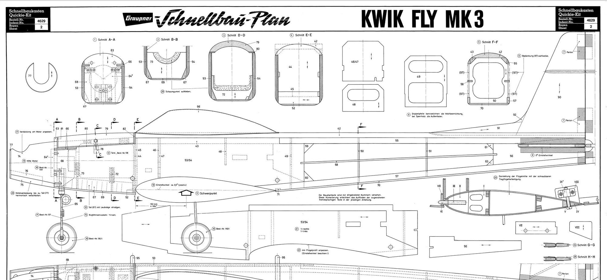
KWIK FLY MK3 based on Graupner plans
 05-30-2026 | 09:13 PM
#1
Thread Starter

Hi all When I was a child, my father had a 1978 Graupner catalog. Flipping through that catalog and looking at the pictures of those airplanes was one of my favorite childhood pastimes. I spent countless hours watching those photos, and I truly dreamed that one day, when I grew up, I would own some of those airplanes.
Airplanes such as the Chico, Amateur, Taxi, Topsy, and of course the beloved Kwik Fly Mk III, designed by Phil Kraft and later released as a kit by Graupner.
And I think that today, at the age of forty, I am finally old enough�and perhaps fortunate enough�to fulfill that childhood dream.
My father was also a modeler, and he always enjoyed seeing the airplanes and projects I built. Unfortunately, I lost him less than a year ago, and I will never have the chance to show him this finished airplane.
Even so, I like to think that he would have been happy to see it, just as he always was.
May the souls of all parents who inspired their children rest in eternal peace.
Last edited by ehsanmorshedi; 05-31-2026 at 12:00 AM.
 05-30-2026 | 09:20 PM
#2
Thread Starter
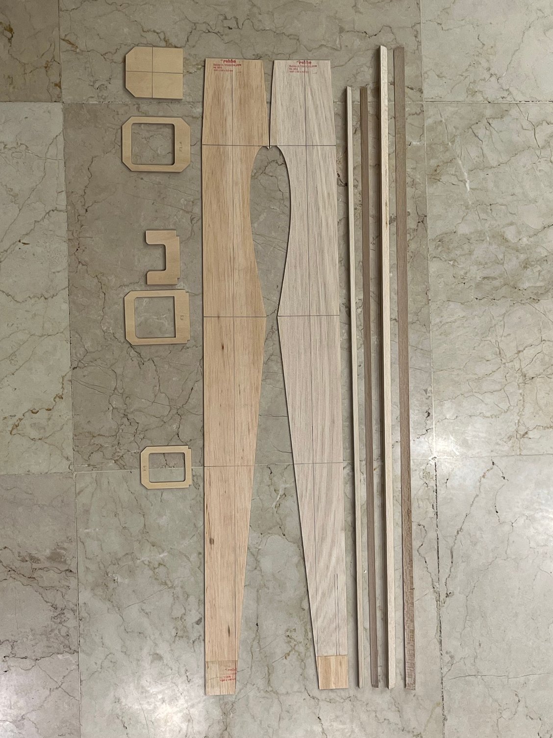
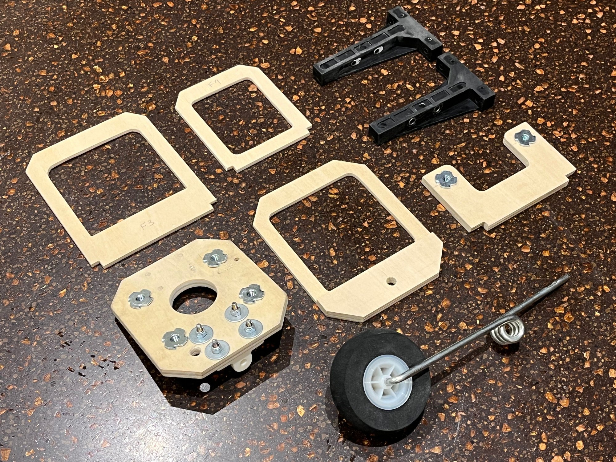
I will use Graupner Plans which are available for download from outerzone.co.uk
plans are very detailed, precise and from my point of view a little bit complicated.
so I will a some modifications to the internal structure with respect to the outer shape of the plane.
In other words I will simplify the structure.
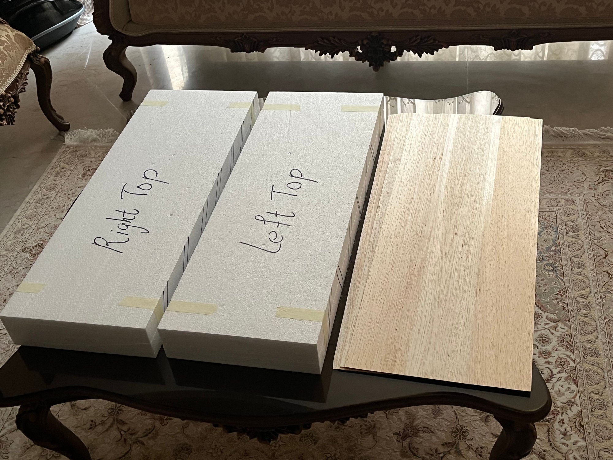
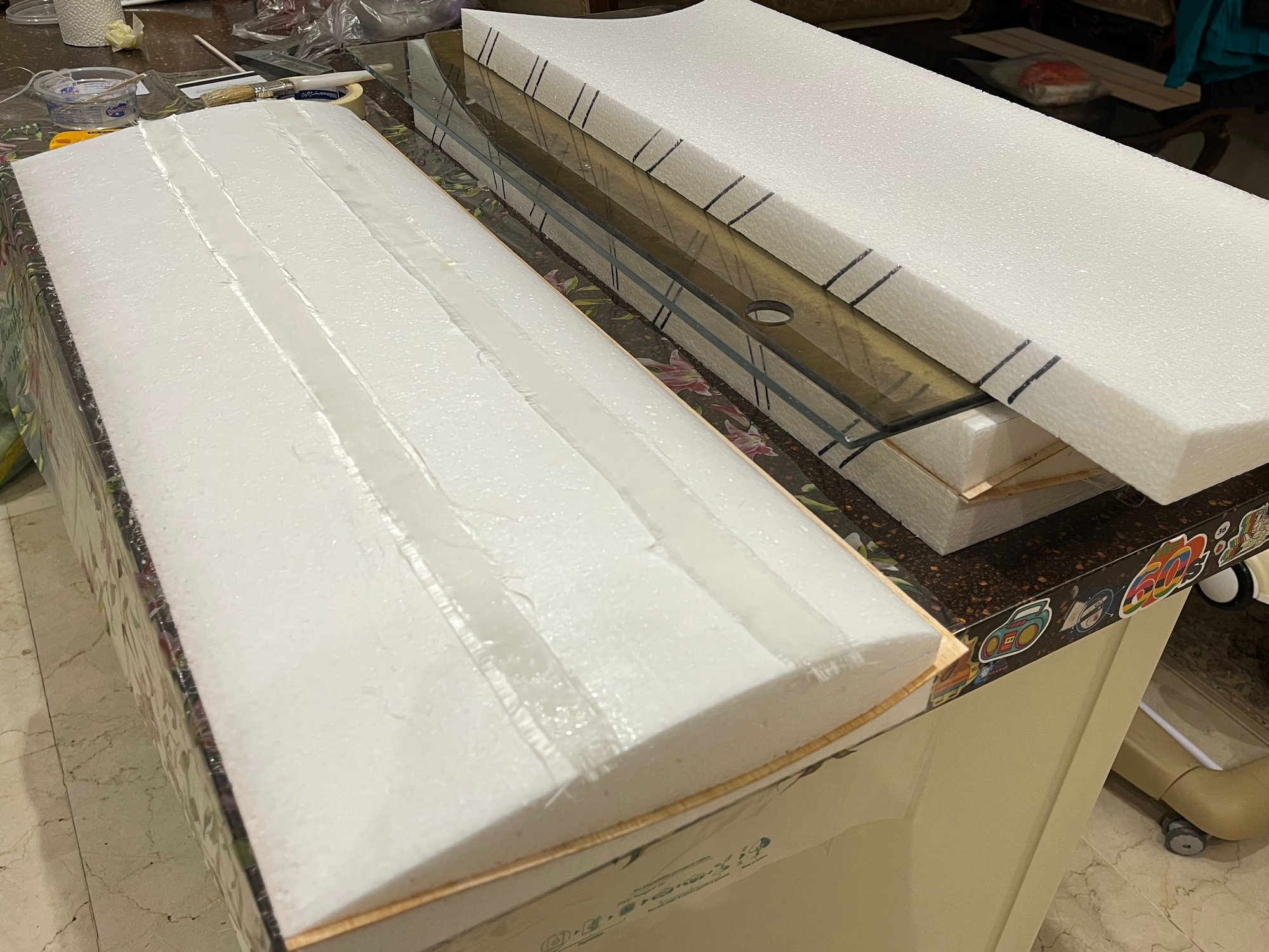
by the way as all my projects I will go for a foam core wing.
plans are very detailed, precise and from my point of view a little bit complicated.
so I will a some modifications to the internal structure with respect to the outer shape of the plane.
In other words I will simplify the structure.
by the way as all my projects I will go for a foam core wing.
05-30-2026 | 09:36 PM
#3
Thread Starter
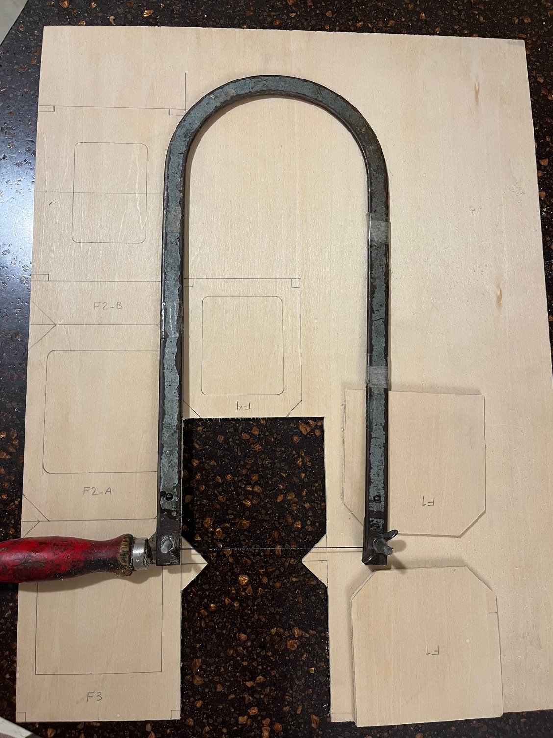
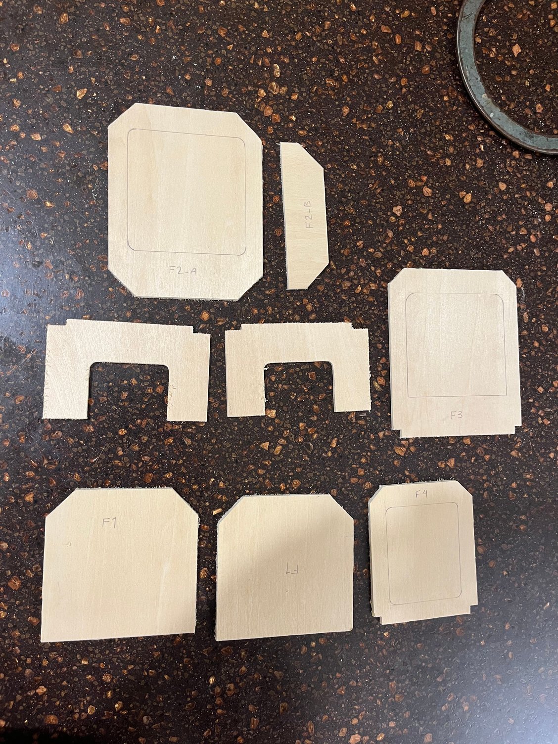
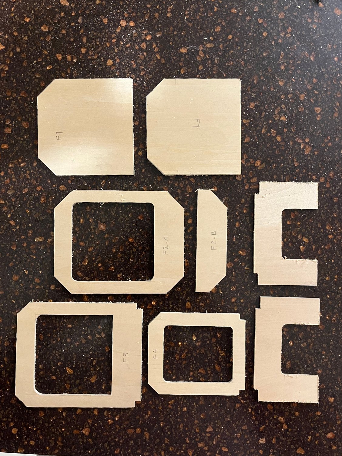
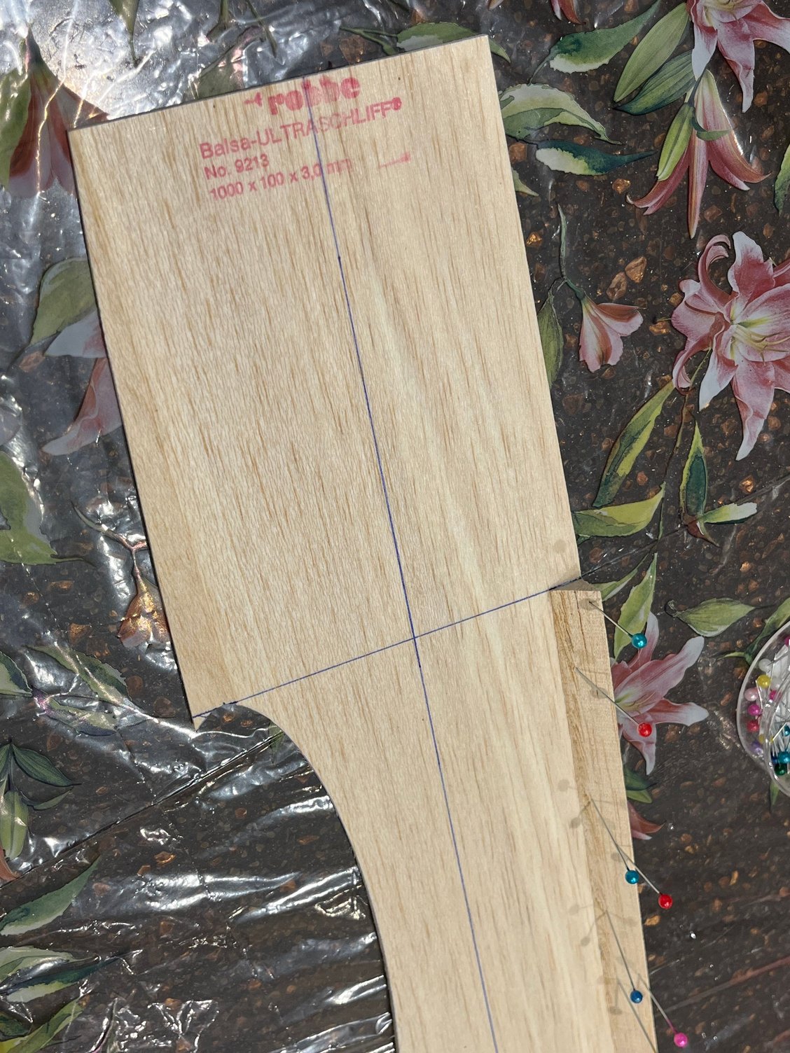
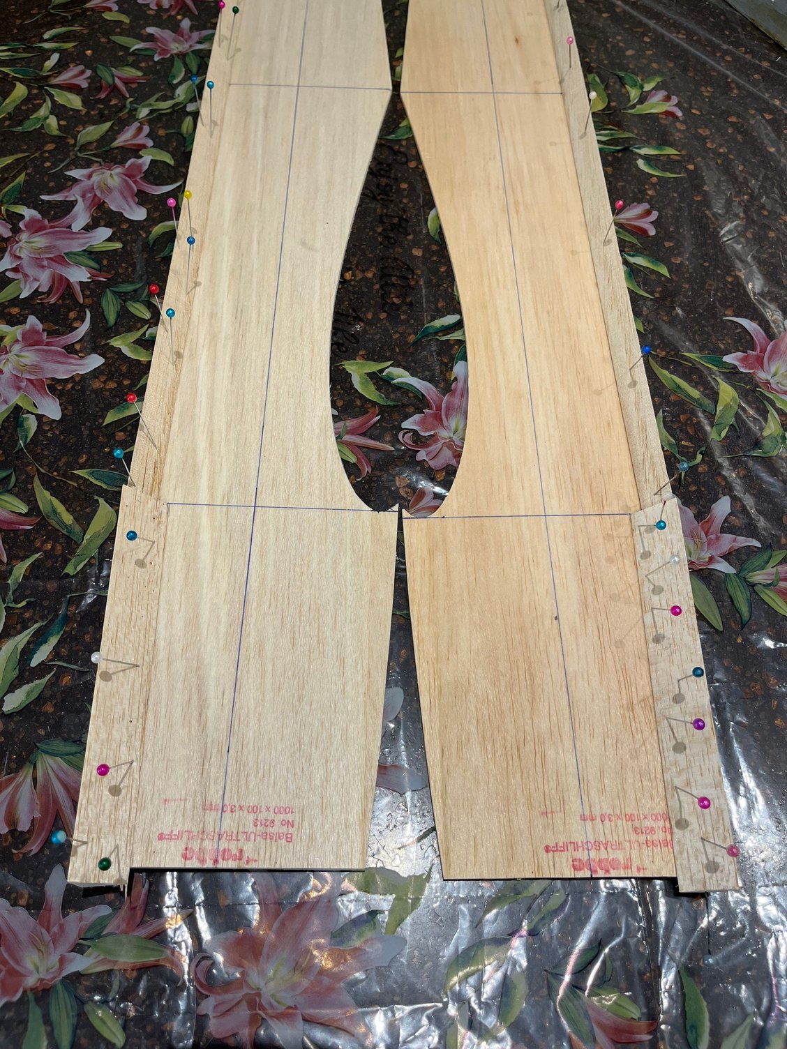
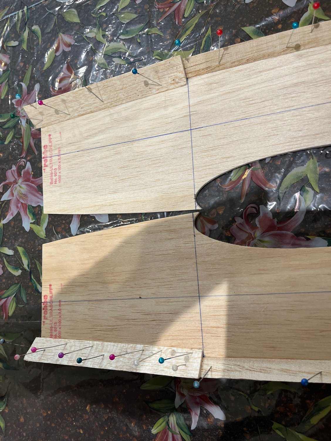
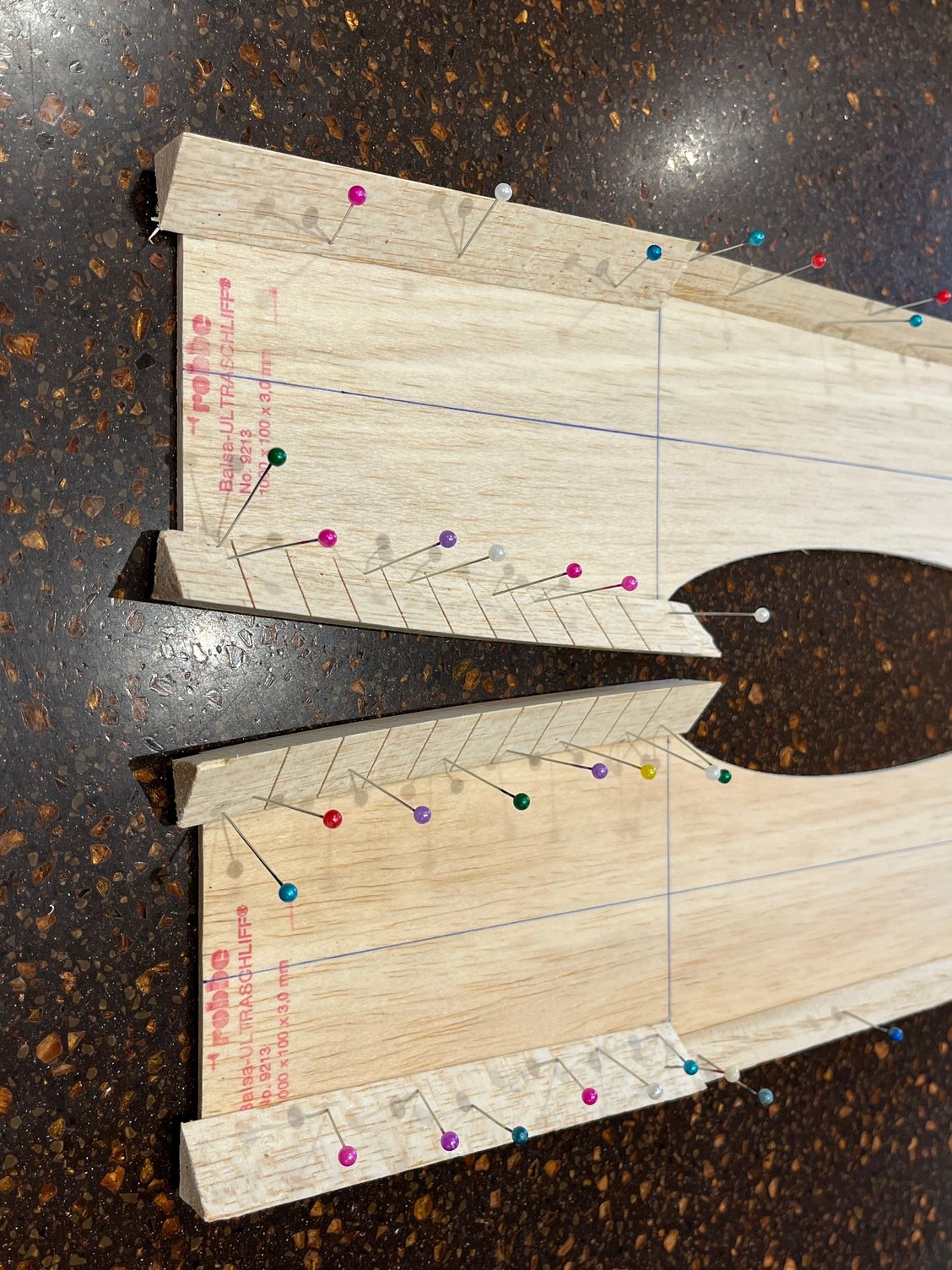
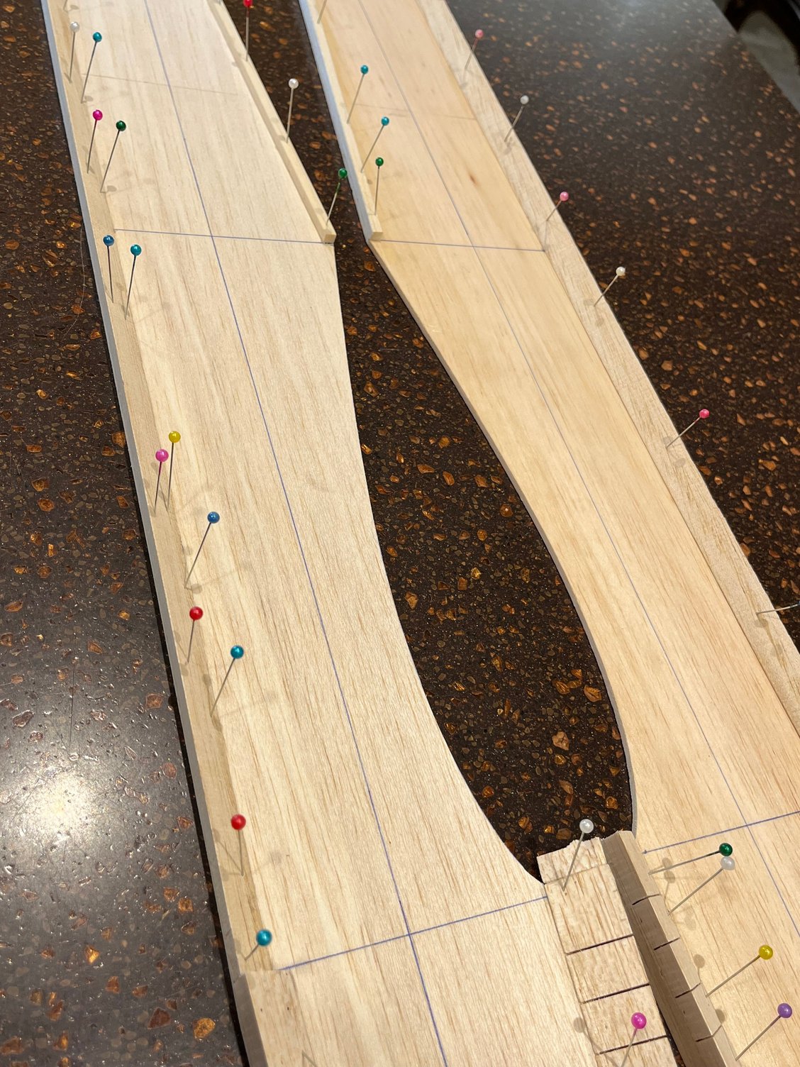
[img alt="Fuselage sides are made of 2 ply of 2.5mm (3/32�) balsa reinforced with a 0.8mm (1/32�) plywood.
There are also open bays in the back which looks to be a little weak.
I will use one piece 3mm (1/8�) balsa sides that are reinforced with a layer of 100 grams glass cloth.
So the thickness of the sides will be less than the plan. This means that the formers should be a little wider compared to the plans to save the outer width of the fuselage.
"]https://cimg2.ibsrv.net/gimg/www.rcuniverse.com-vbulletin/2000x922/img_4130_d31b99722989f996503c96310fc4e375f4c3cdec. jpeg[/img]
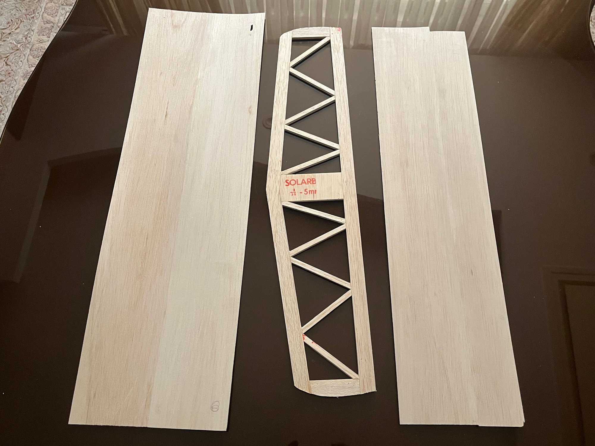
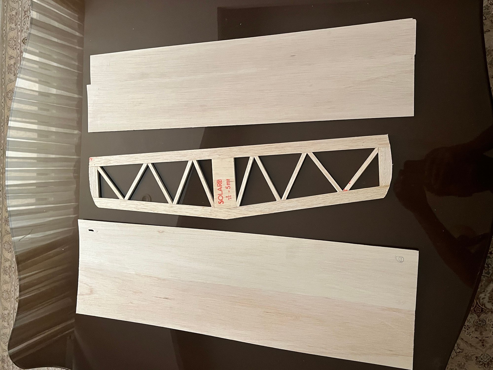
Fuselage sides are made of 2 ply of 2.5mm (3/32�) balsa reinforced with a 0.8mm (1/32�) plywood. There are also open bays in the back which looks to be a little weak. I will use one piece 3mm (1/8�) balsa sides that are reinforced with a layer of 100 grams glass cloth. So the thickness of the sides will be less than the plan. This means that the formers should be a little wider compared to the plans to save the outer width of the fuselage.
There are also open bays in the back which looks to be a little weak.
I will use one piece 3mm (1/8�) balsa sides that are reinforced with a layer of 100 grams glass cloth.
So the thickness of the sides will be less than the plan. This means that the formers should be a little wider compared to the plans to save the outer width of the fuselage.
"]https://cimg2.ibsrv.net/gimg/www.rcuniverse.com-vbulletin/2000x922/img_4130_d31b99722989f996503c96310fc4e375f4c3cdec. jpeg[/img]
Fuselage sides are made of 2 ply of 2.5mm (3/32�) balsa reinforced with a 0.8mm (1/32�) plywood. There are also open bays in the back which looks to be a little weak. I will use one piece 3mm (1/8�) balsa sides that are reinforced with a layer of 100 grams glass cloth. So the thickness of the sides will be less than the plan. This means that the formers should be a little wider compared to the plans to save the outer width of the fuselage.
 05-30-2026 | 09:45 PM
#5
Thread Starter
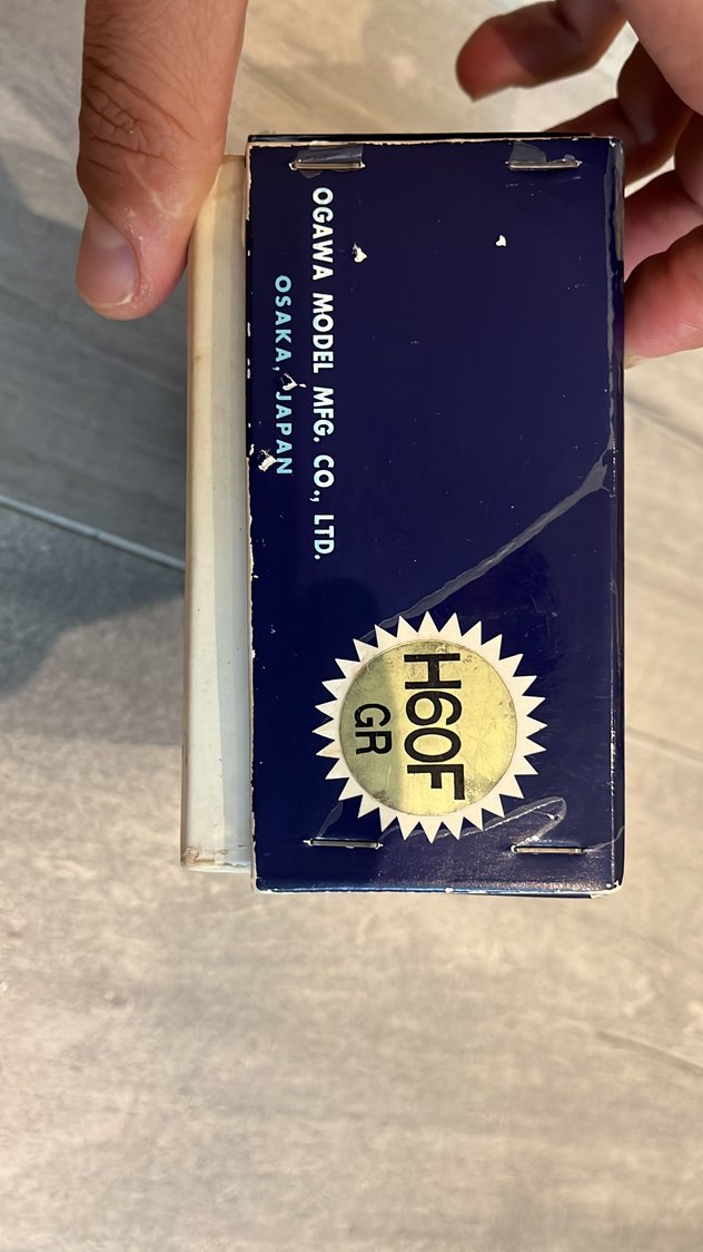
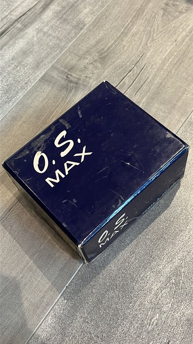
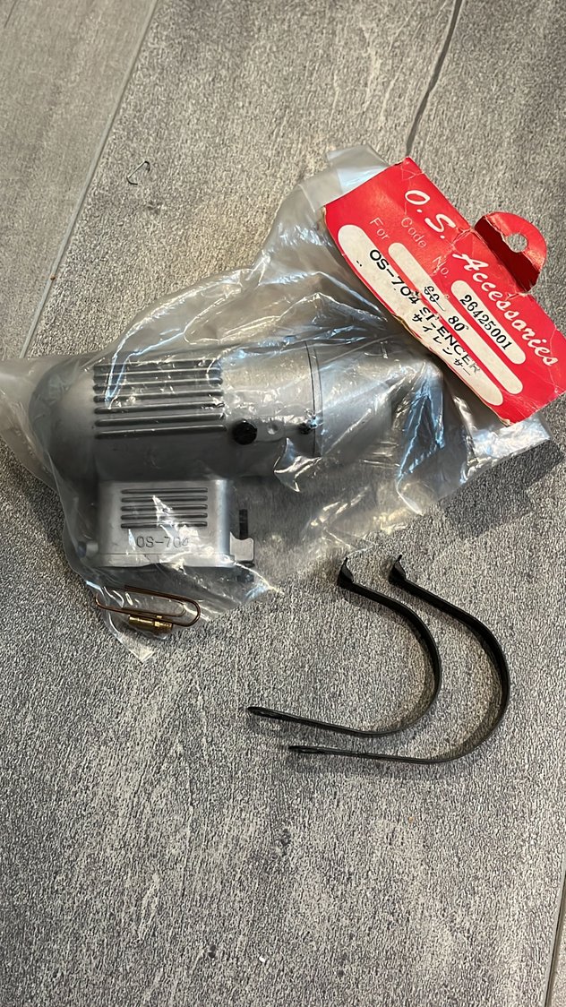
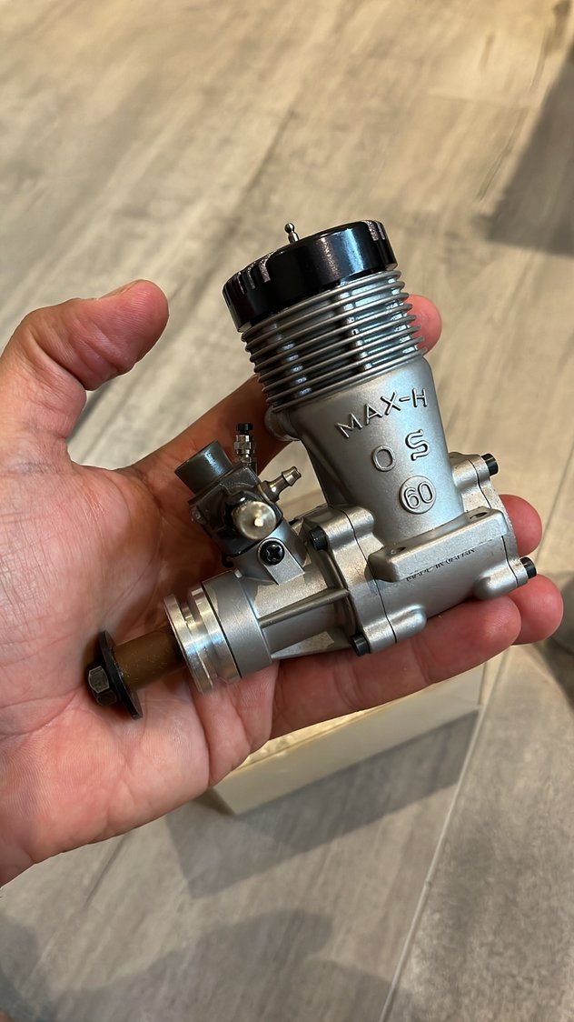
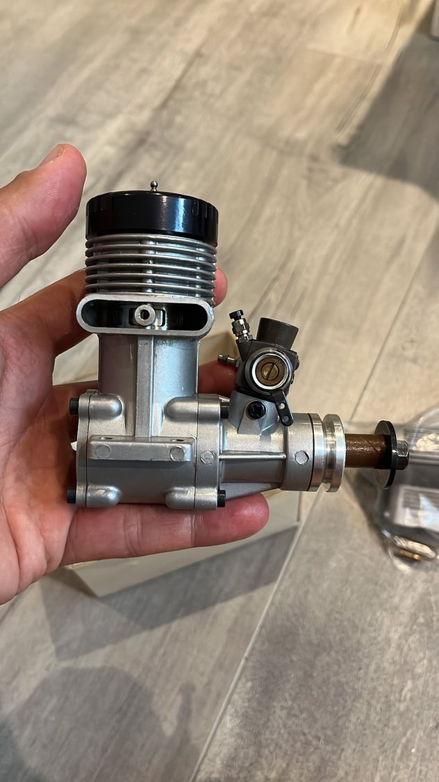
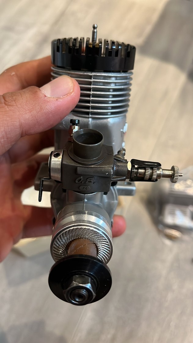
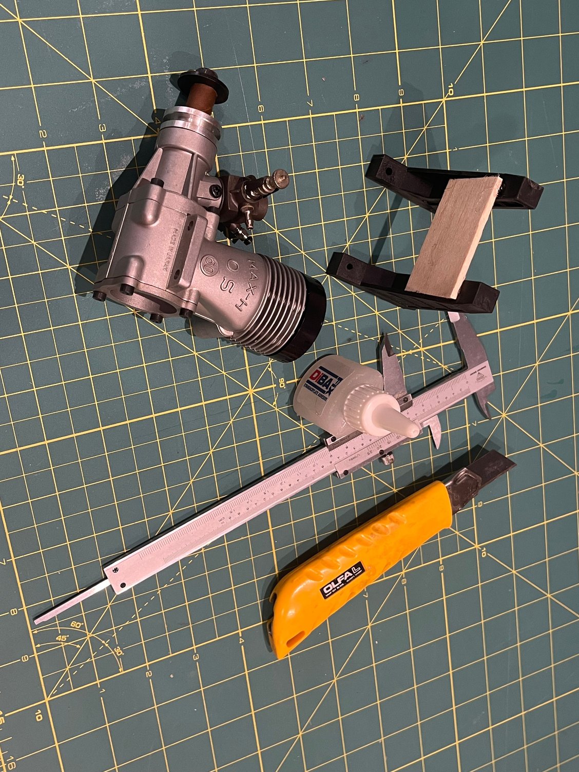
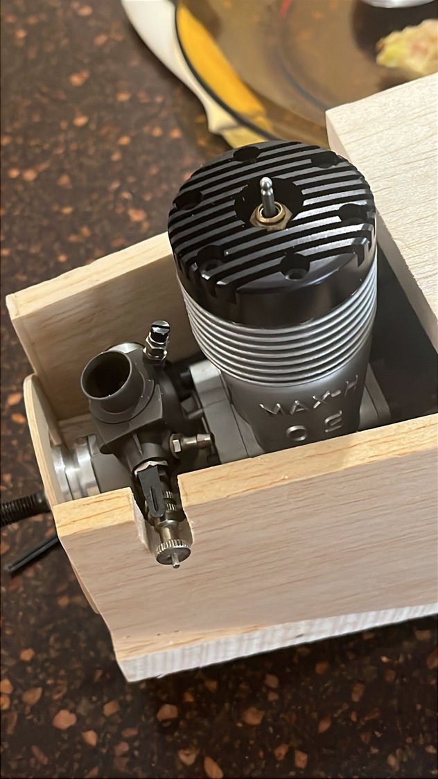
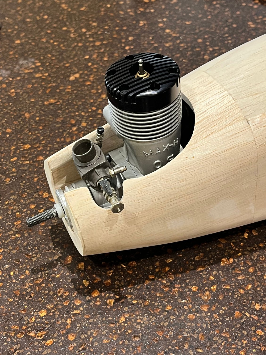
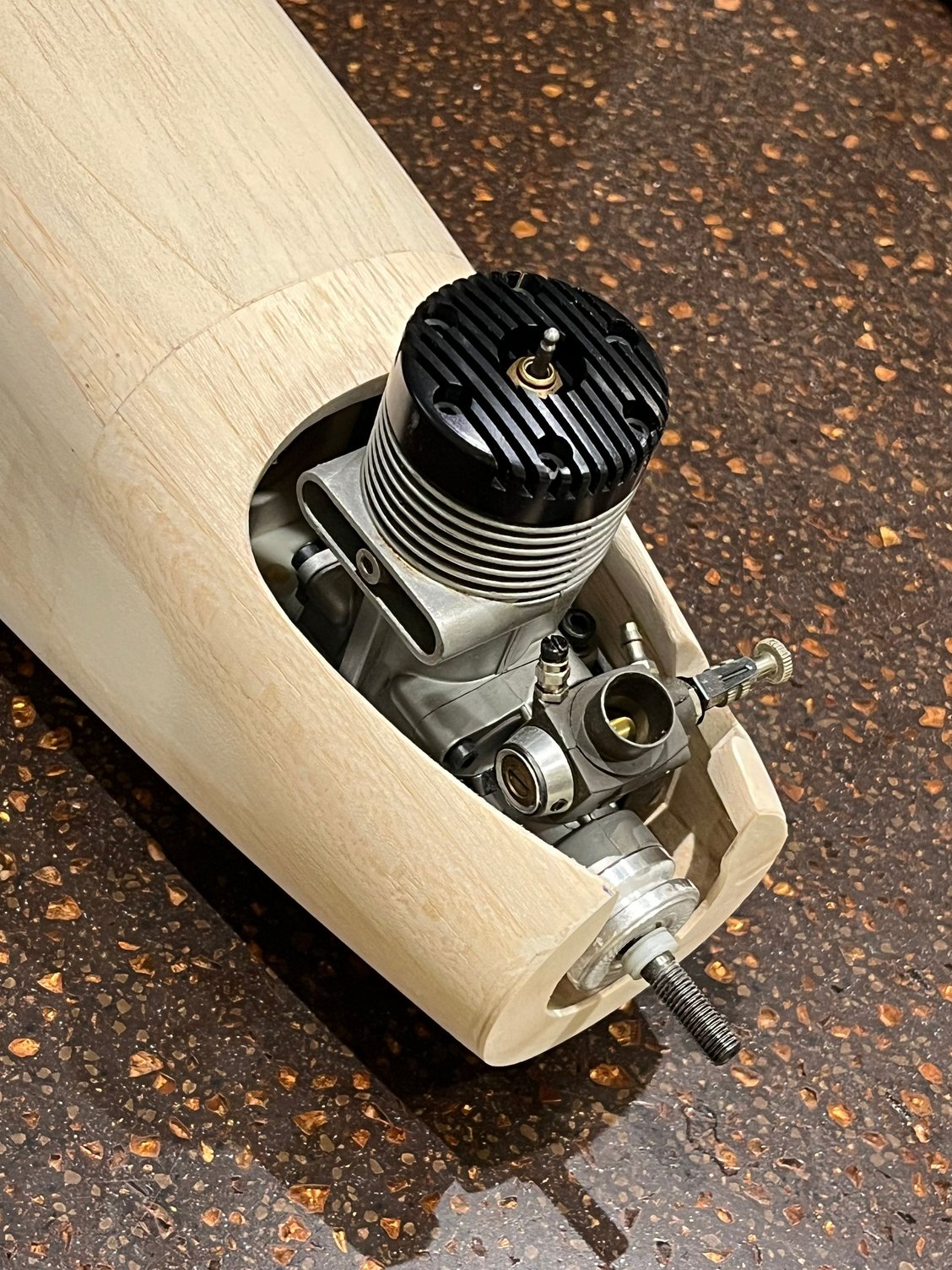
The engine will be exactly the one in the Graupner 1978 catalog, an OS max H60F GR black head.
Was so lucky to find a NIB one with muffler from ebay last year.
Was so lucky to find a NIB one with muffler from ebay last year.


 05-30-2026 | 10:56 PM
#7
Thread Starter
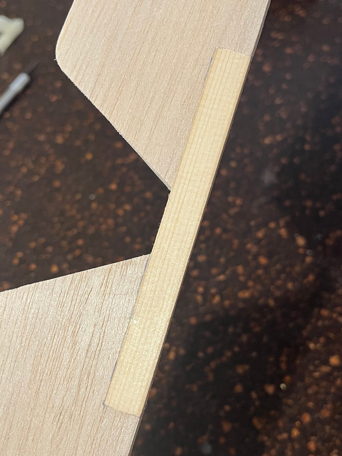
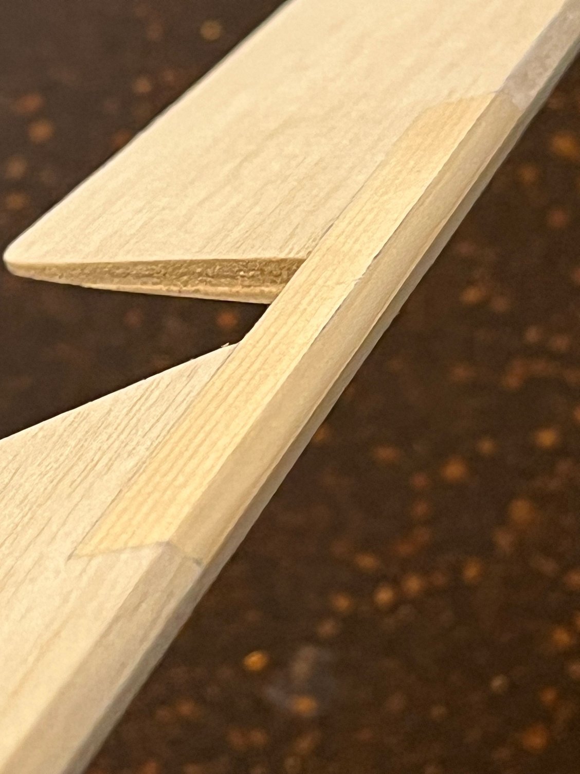
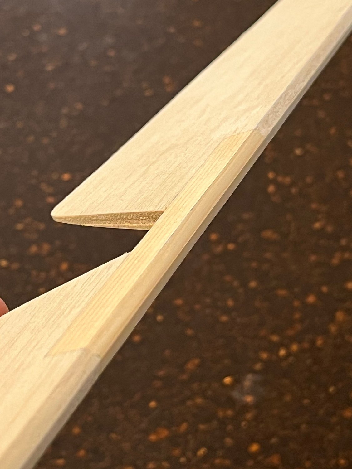
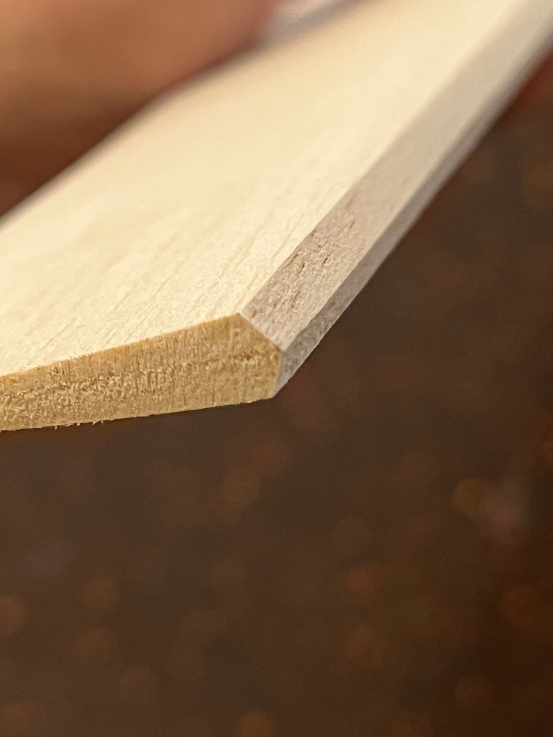
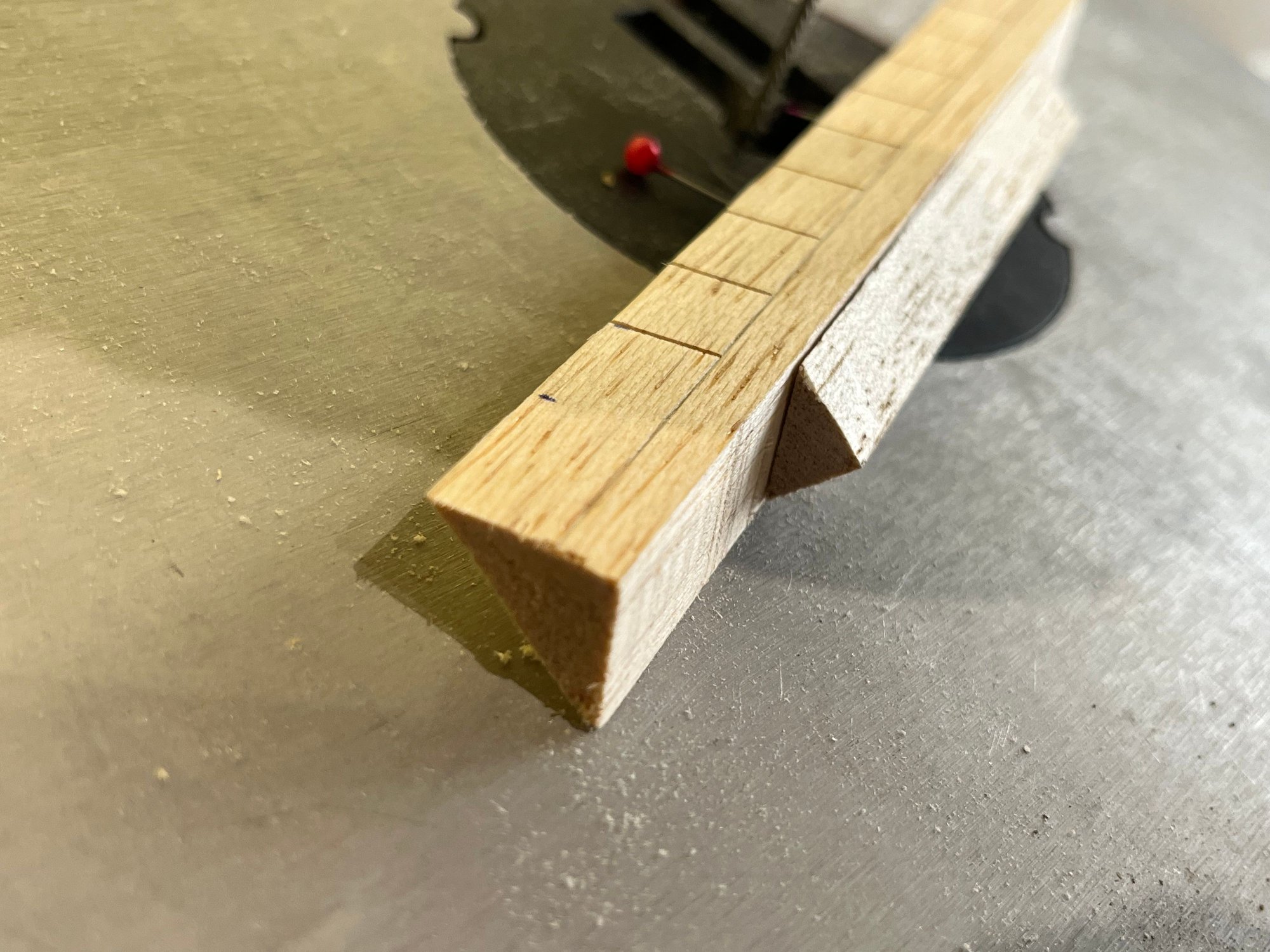
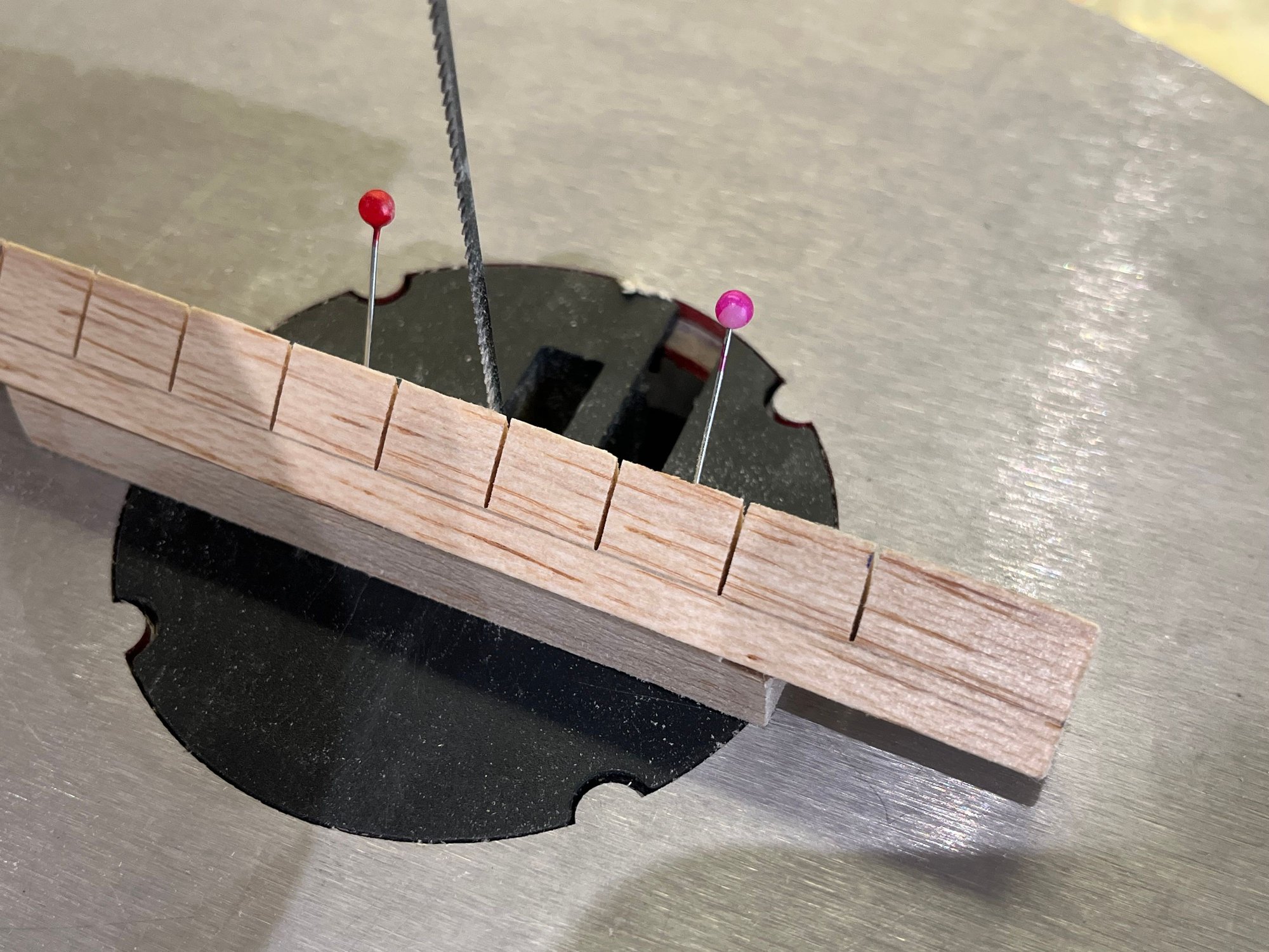
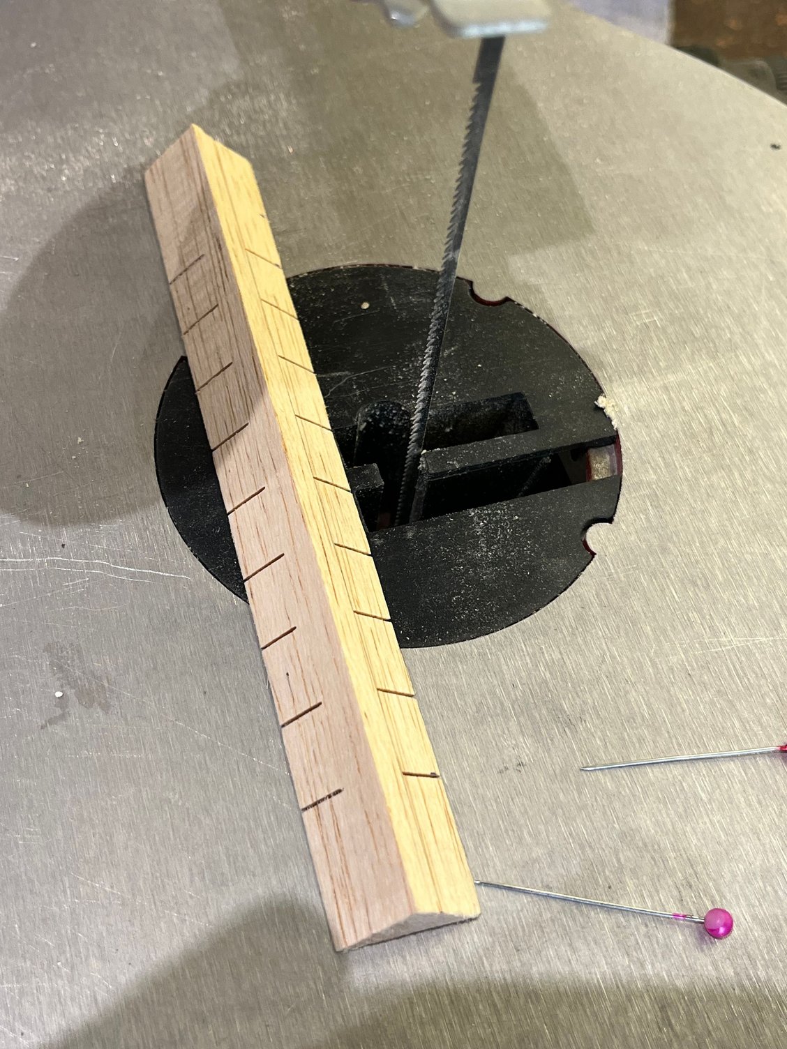
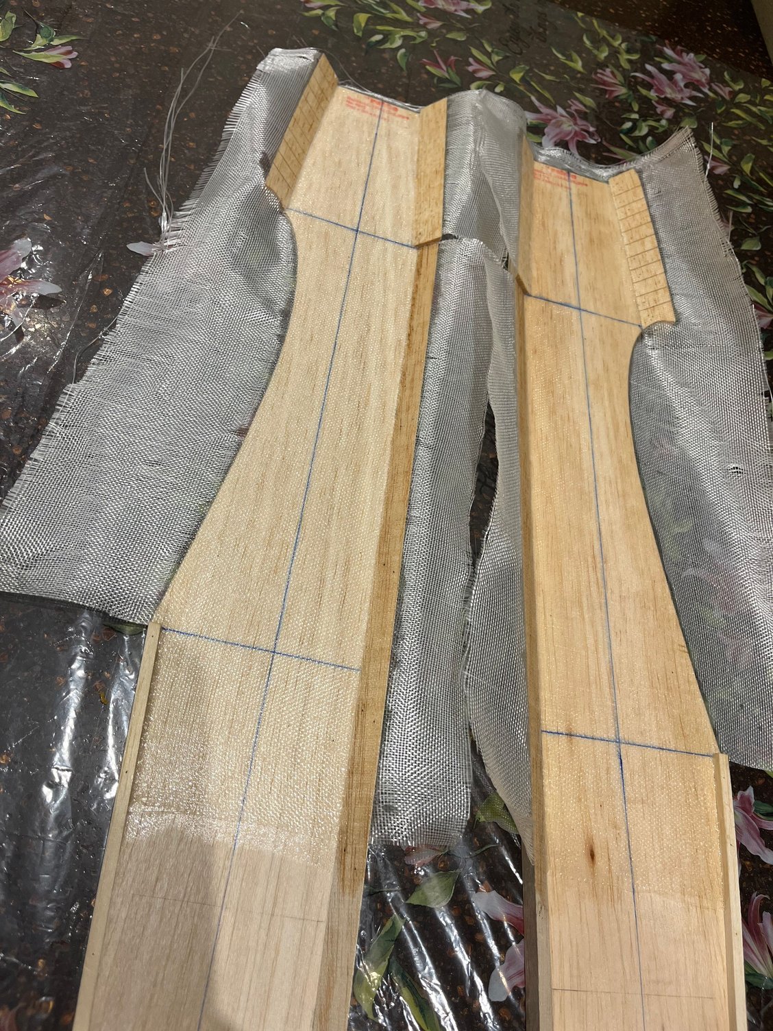
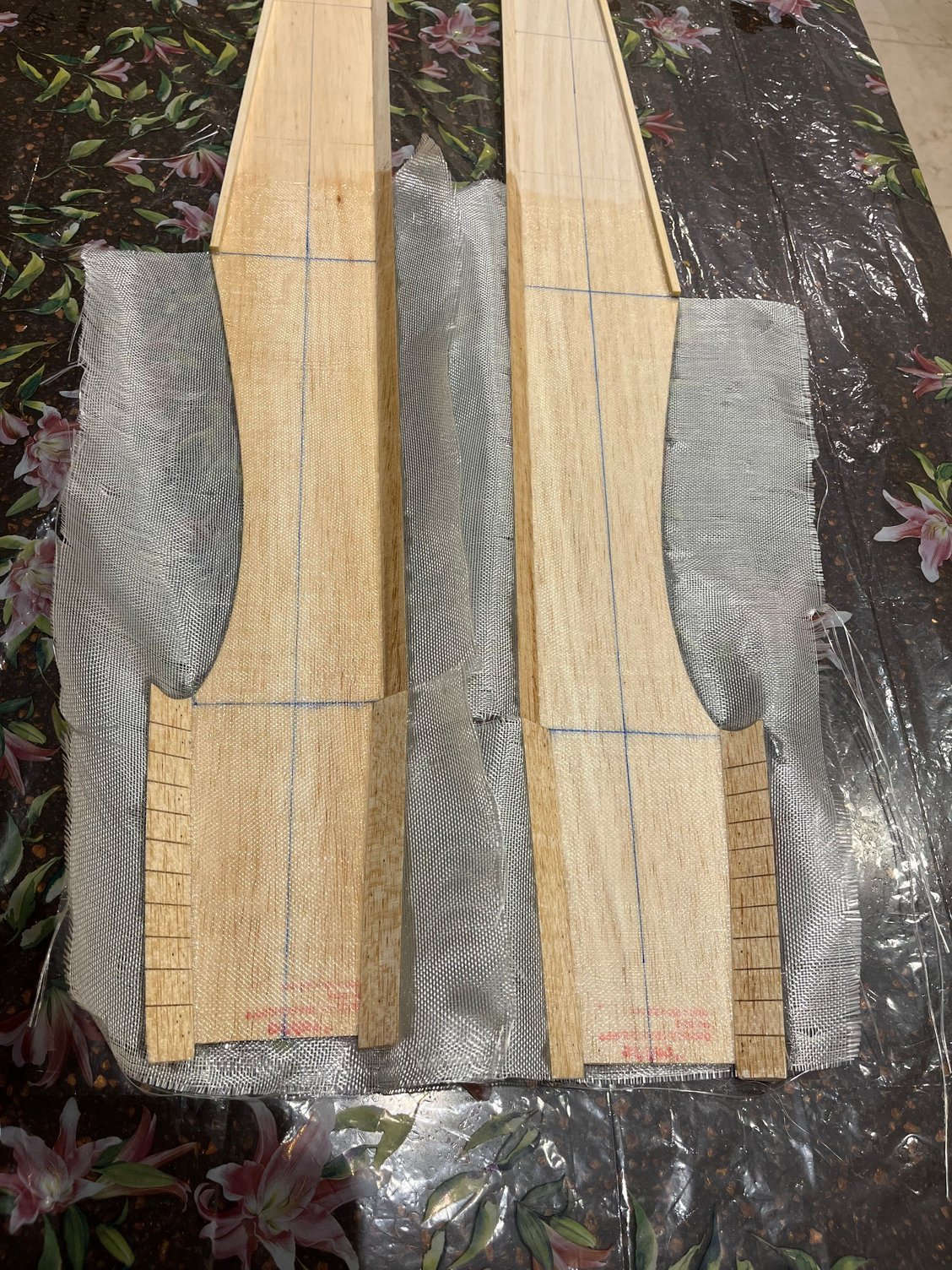
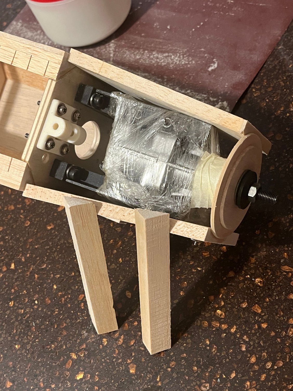
Other changes, in addition to the modified fuselage sides and the redesign of the formers, will include the use of triangular longerons in the corners and a top fuselage sheeting consisting of two layers of 5 mm balsa.
following the same construction method that Joe Bridi employed in many of his aircraft designs.
following the same construction method that Joe Bridi employed in many of his aircraft designs.
The following users liked this post:
scottrc (06-01-2026)
The following users liked this post:
scottrc (06-01-2026)
05-31-2026 | 03:40 AM
#10

My Feedback: (121)
Very nice work. I admire your patience to hand cut parts with a coping saw. I have a band saw and a jig saw which speed up the process. The OS blackhead is a very nice engine. Not a powerhouse, by today’s standards, but perfect for the Kwik Fli. Looking forward to the rest of your build and, of course, the flight report.
-Will
-Will
05-31-2026 | 06:32 PM
#11
Thread Starter
Thanks
The main reason I chose this engine was that I wanted the airplane to look exactly like it does in the Graupner catalog photos.
I doubt it produces any more power than a modern .46 or .50 engine.
The main reason I chose this engine was that I wanted the airplane to look exactly like it does in the Graupner catalog photos.
I doubt it produces any more power than a modern .46 or .50 engine.
05-31-2026 | 06:43 PM
#12
Thread Starter
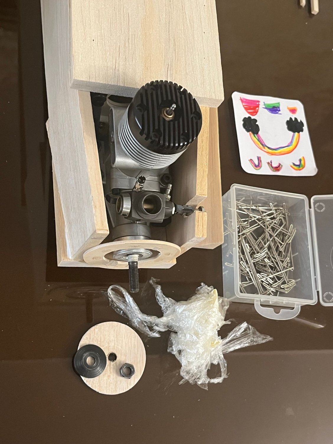
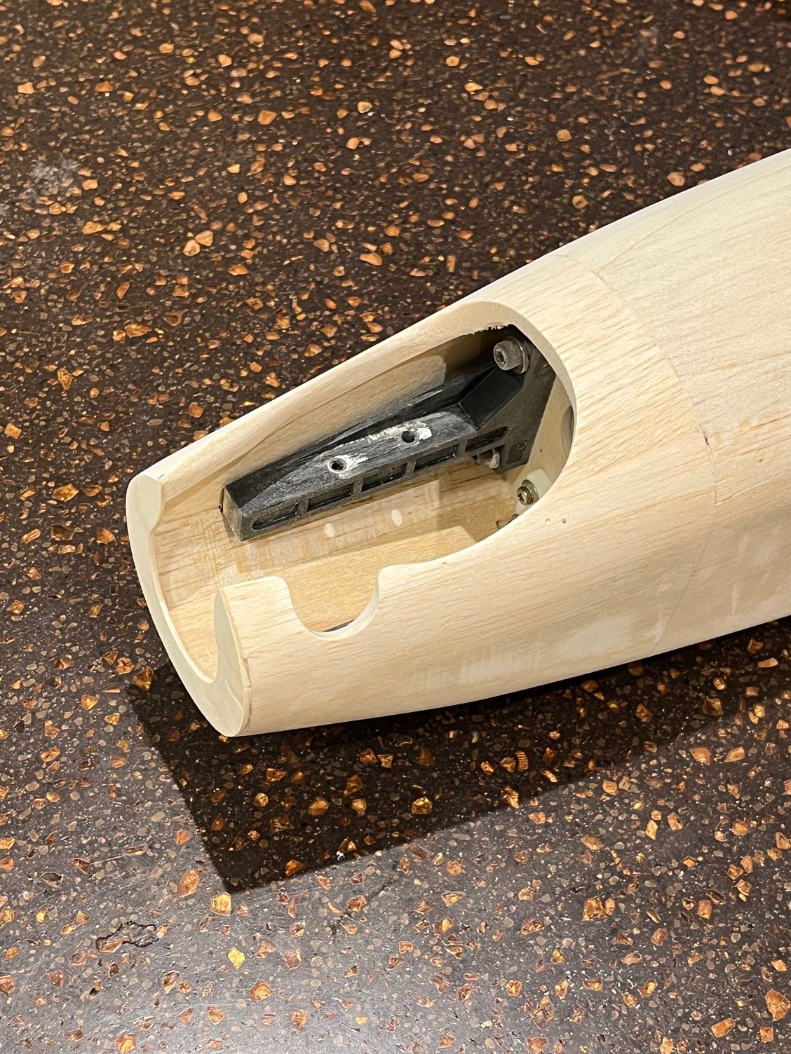
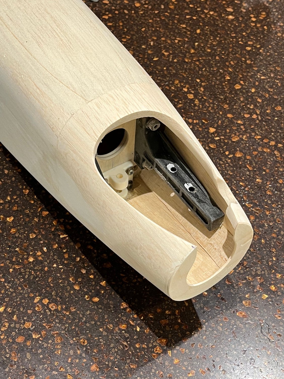
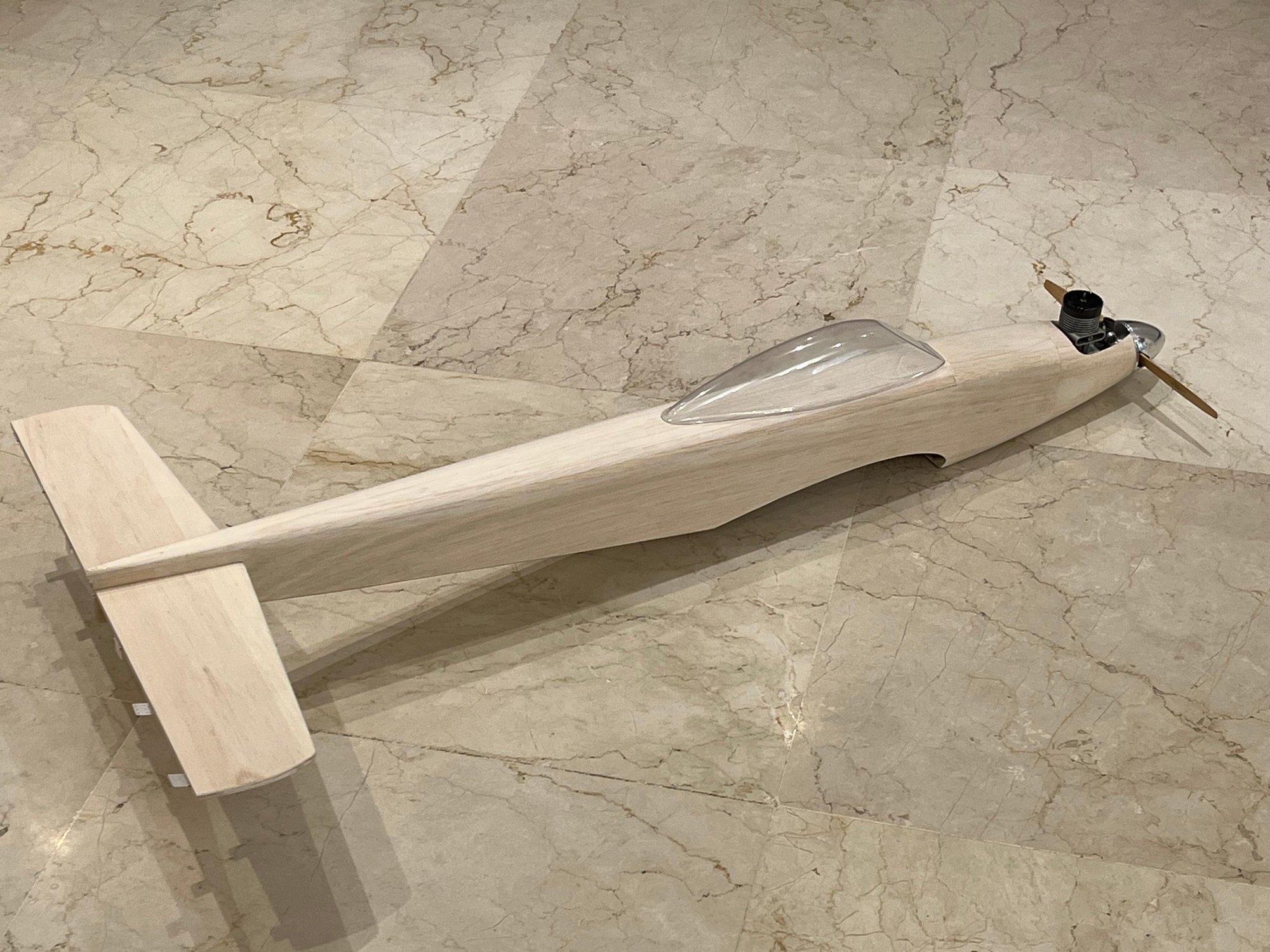
I finally found some time and managed to get the fuselage framed up.
Now it�s time to move on to the cowl and start fitting the wood blocks in that area.
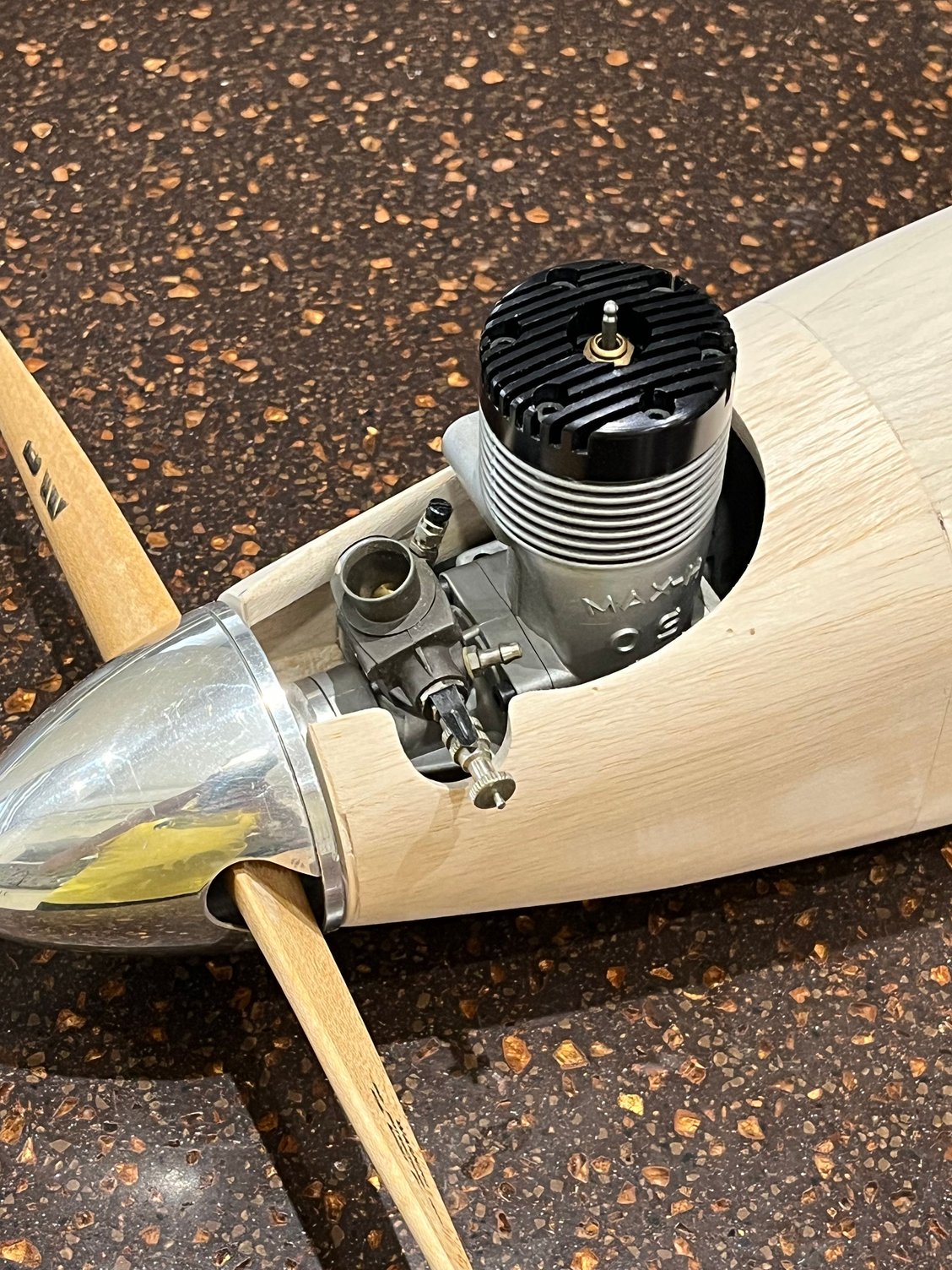
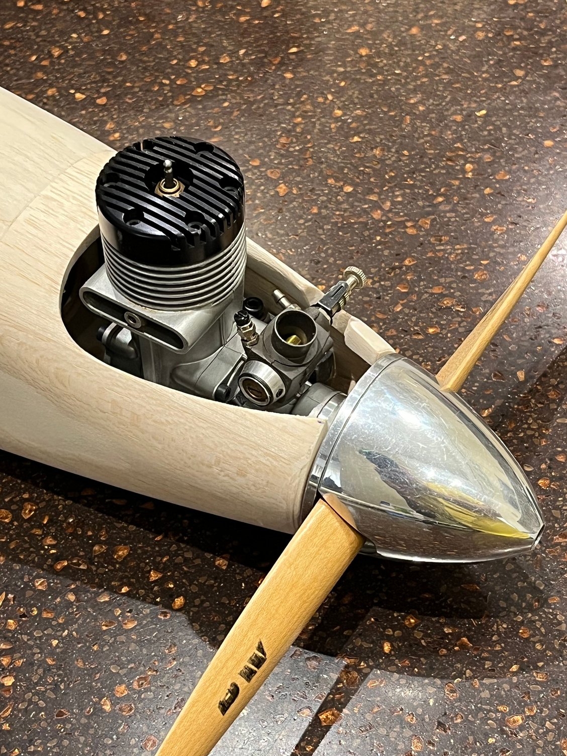
One of the details I�ve always appreciated on model airplanes is having the spinner backplate sit with a nice, even gap to the cowl.
At the same time, I don�t like the cowl opening to be overly large, leaving too much of the engine exposed. I prefer a balance where there�s still good access to the engine, while keeping it sufficiently enclosed for a clean, scale-like appearance
Now it�s time to move on to the cowl and start fitting the wood blocks in that area.
One of the details I�ve always appreciated on model airplanes is having the spinner backplate sit with a nice, even gap to the cowl.
At the same time, I don�t like the cowl opening to be overly large, leaving too much of the engine exposed. I prefer a balance where there�s still good access to the engine, while keeping it sufficiently enclosed for a clean, scale-like appearance
05-31-2026 | 06:52 PM
#13
Thread Starter
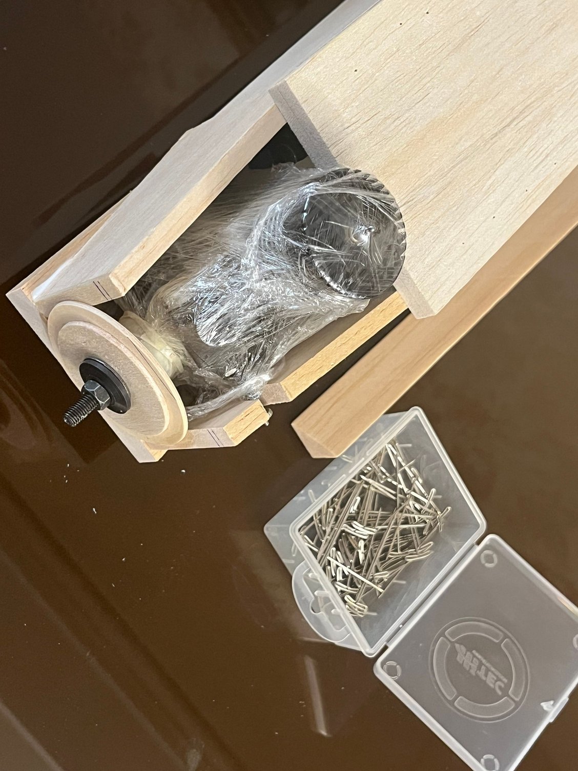
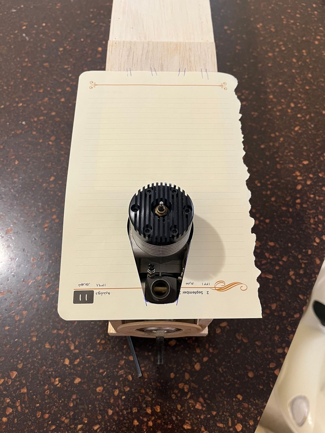
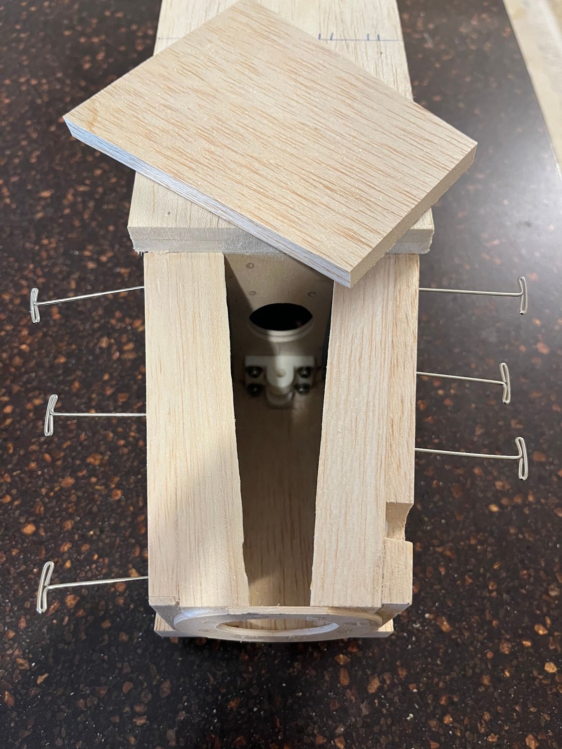
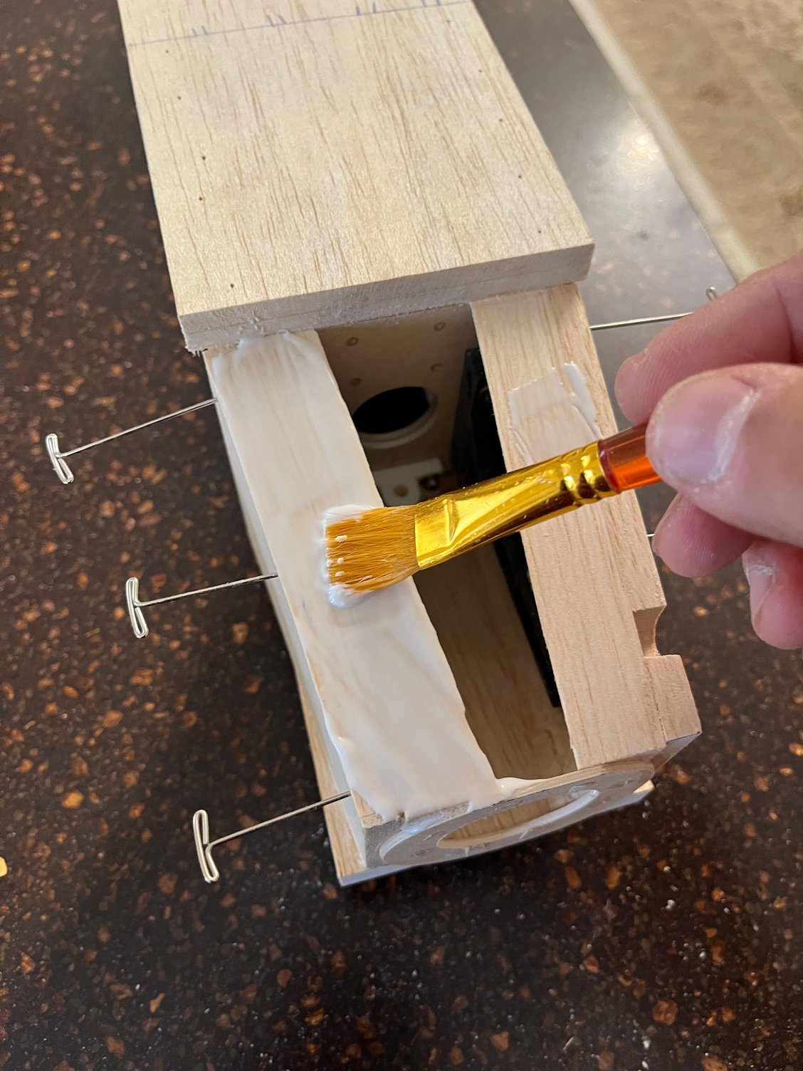
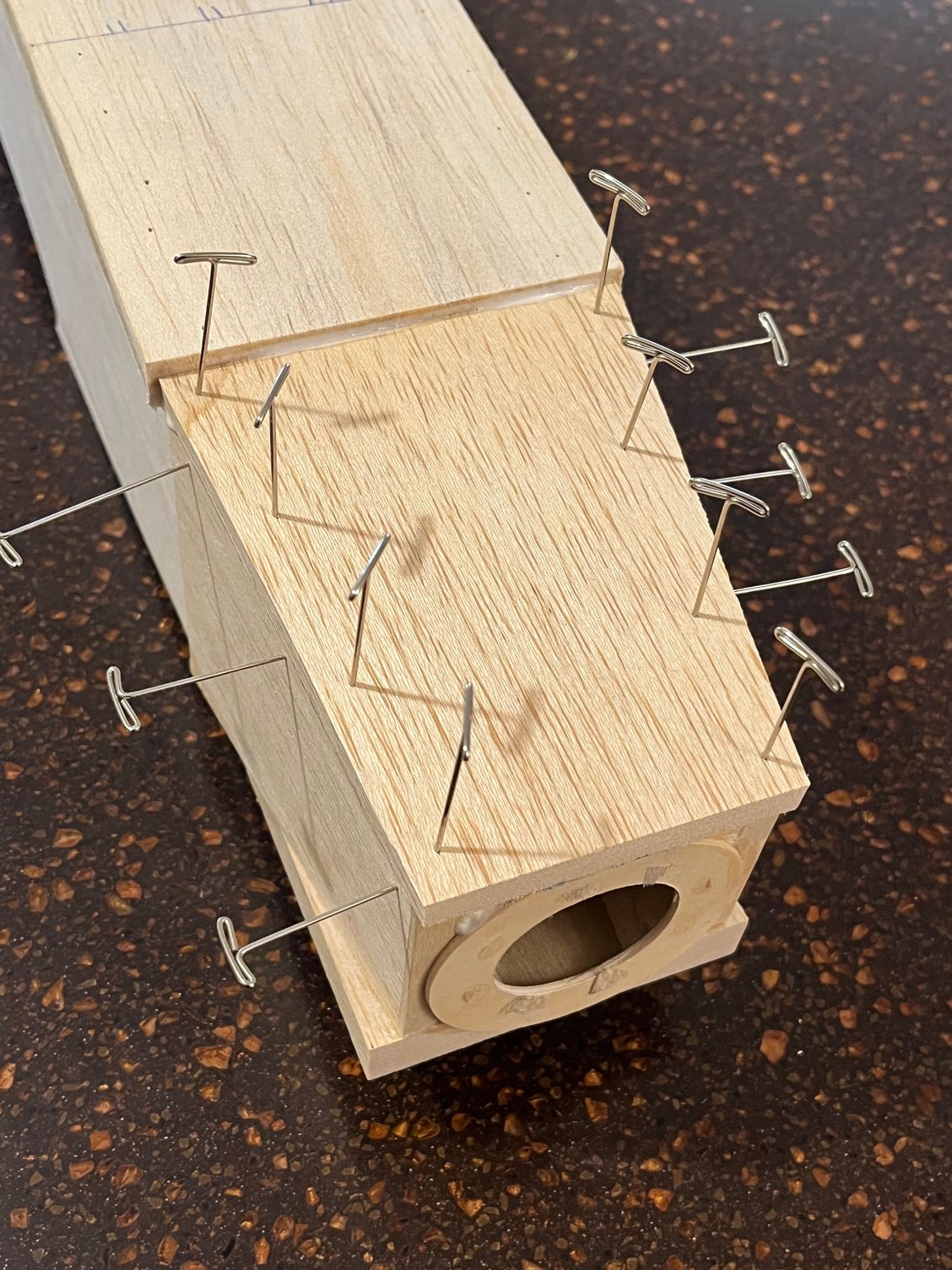
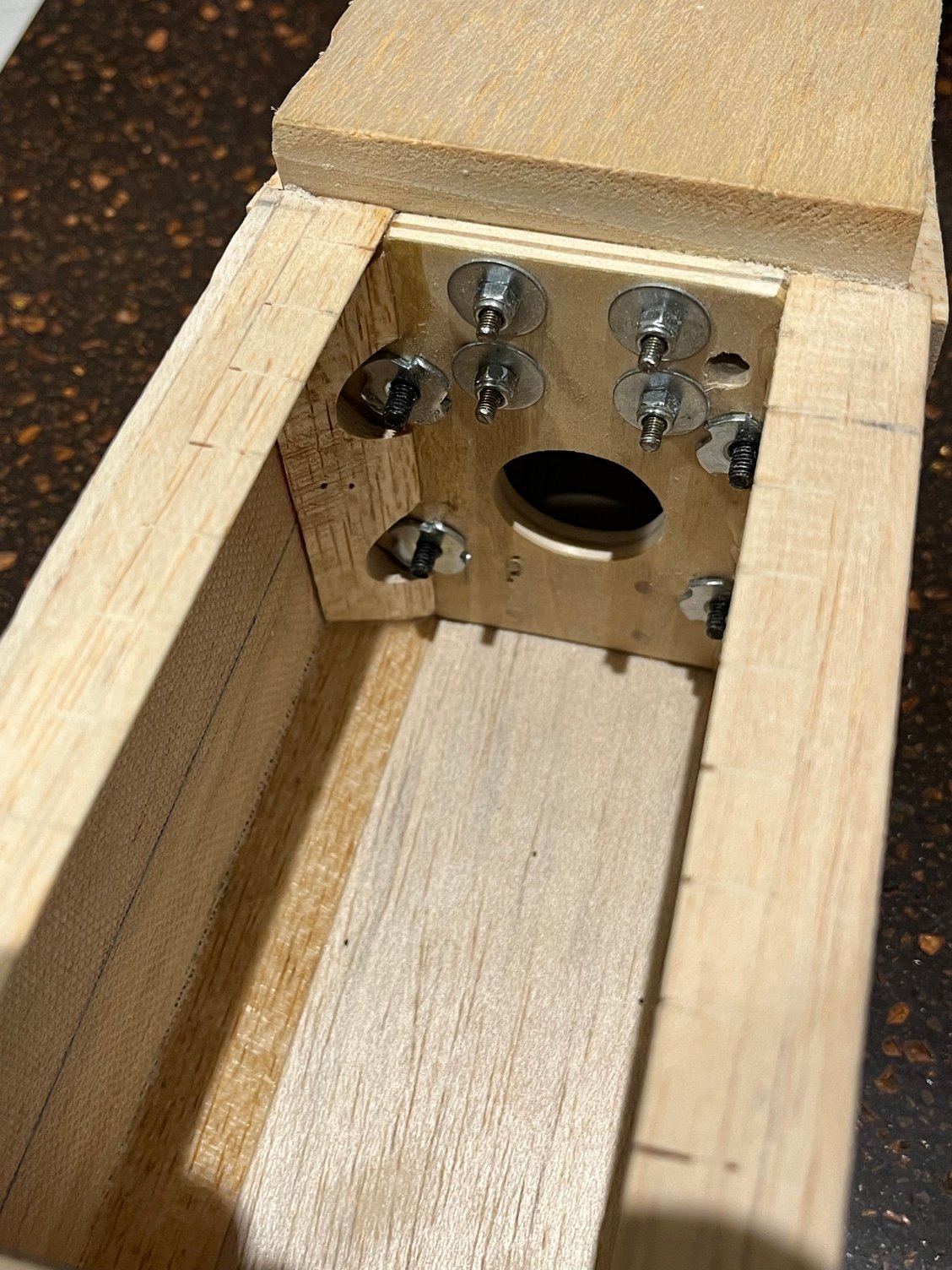
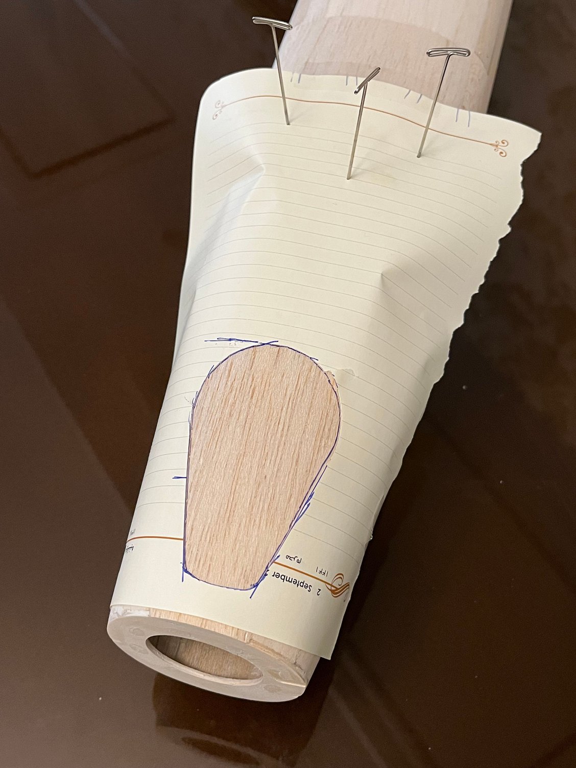
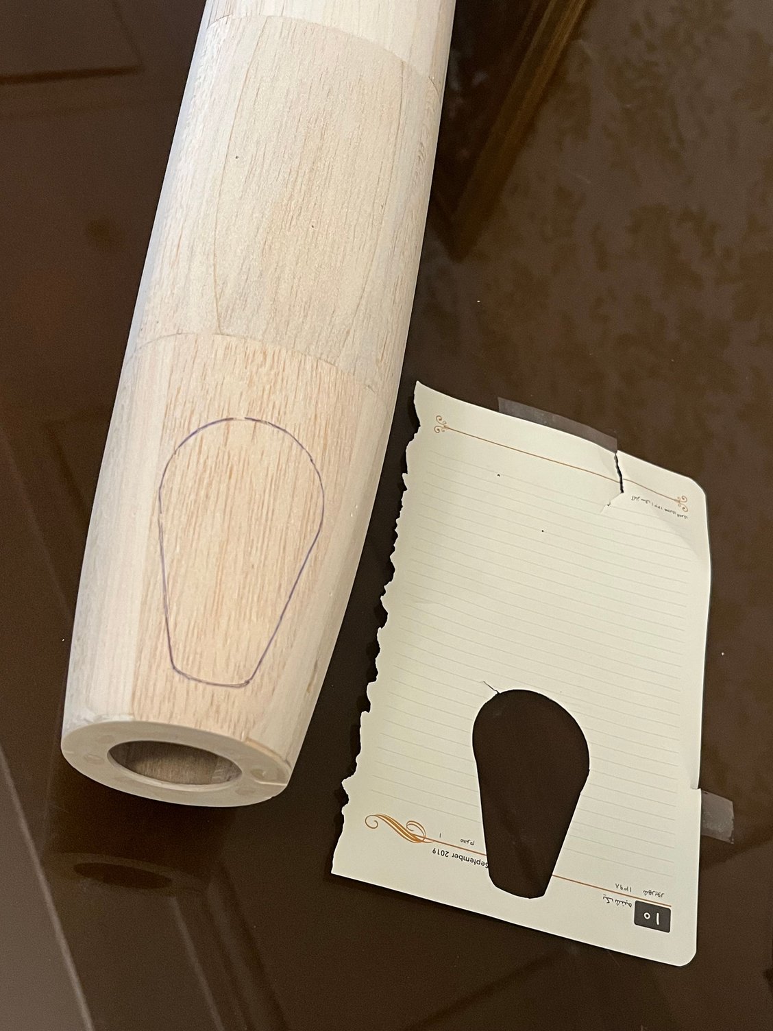
This is probably a method many of you already use, and it�s the one I prefer as well.
Before mounting the engine, I make a paper template with a cutout that represents the exact clearance I want between the engine and the cowl all the way around.
I then mount the engine on the airplane, place the template in position, and mark its location on the fuselage with a pencil. That way, even after removing the engine, I can put the template back in exactly the same spot using those reference marks.
Once the engine is removed, I start building up the cowl area by adding wood blocks until I have a solid structure to work with. Then I reposition the template using the reference marks and transfer the same opening onto the wood blocks.
I�ve found this method to be fairly accurate and repeatable, with very little error.
The following photos should help illustrate the process better than words.


The following users liked this post:
scottrc (06-01-2026)
06-01-2026 | 05:17 AM
#15

Nice build log showing the old school methods. Hope to see your Kwik Fly completed and flying. That OS 60 is one beautiful engine and is in pristine condition.
I see your location and if you are still in Tehran, then I commend you for stepping out of the confines and constraints our politicians put on us and sharing your talent of building with the rest of the world who enjoys our hobby.
Scott
I see your location and if you are still in Tehran, then I commend you for stepping out of the confines and constraints our politicians put on us and sharing your talent of building with the rest of the world who enjoys our hobby.
Scott
06-01-2026 | 08:48 AM
#16
Thread Starter
Hi Scott,
Thank you very much for your kind and heartfelt message.
The art of model building is a shared language and a common passion that transcends political and geographical boundaries, bringing people closer together.
I hope the day comes when I can join you and other fellow enthusiasts without any restrictions, so that we can enjoy working on and flying our model airplanes together. And I hope that one day you will also be able to visit us without any limitations and be our guest.
Life is nothing more than these moments we share.
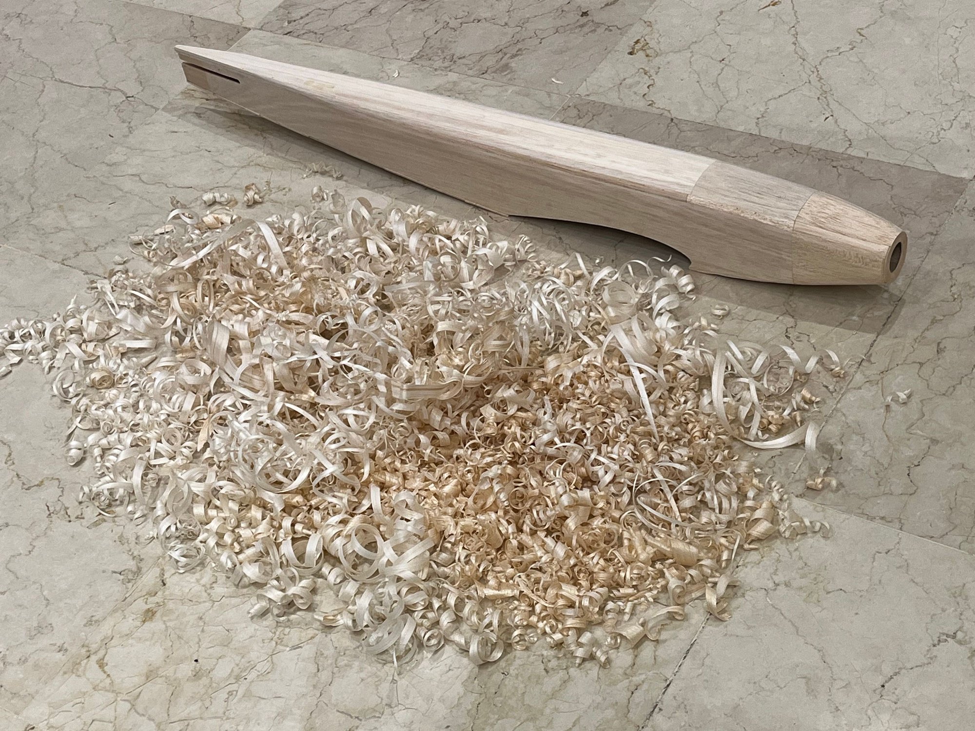
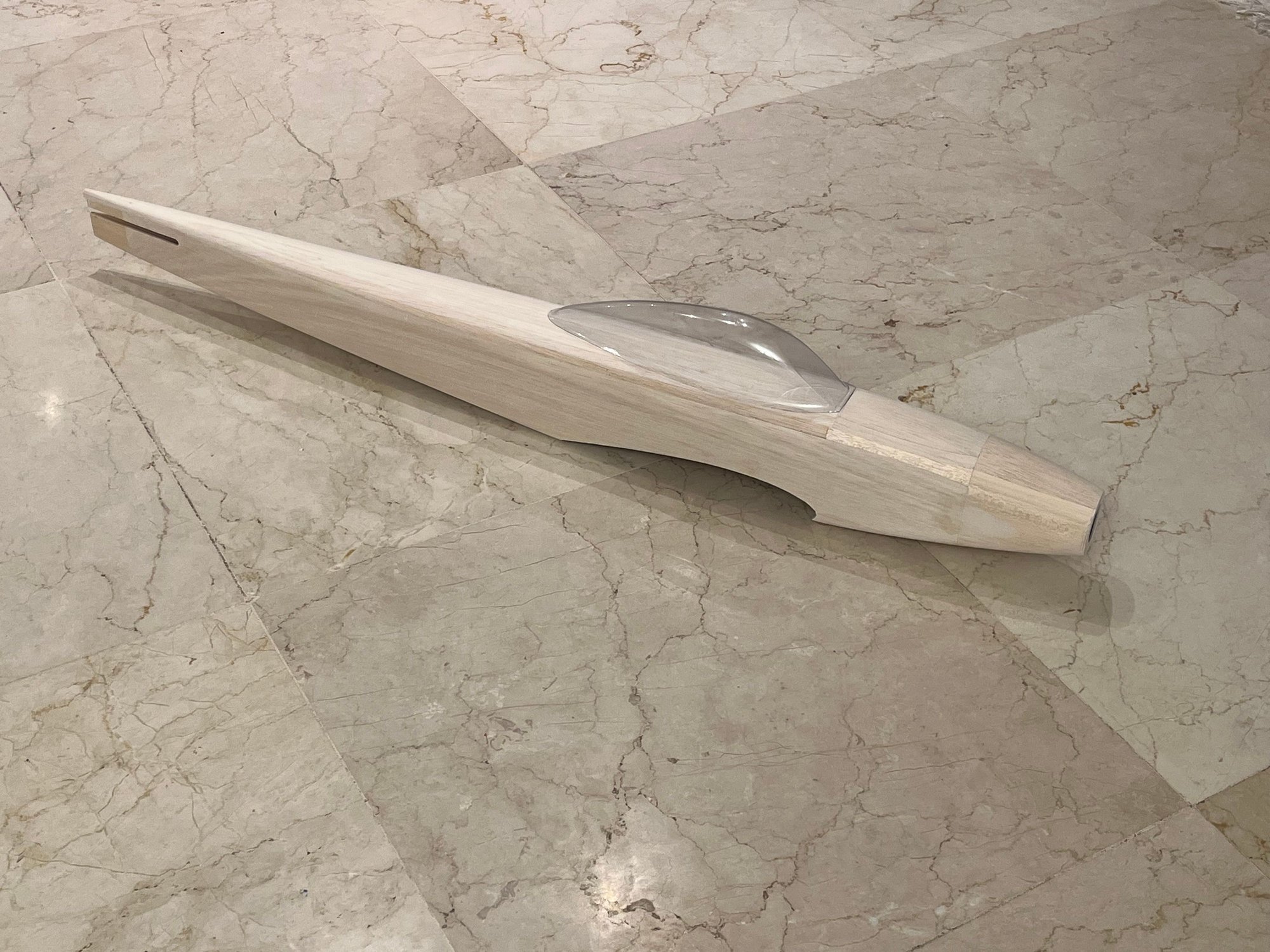
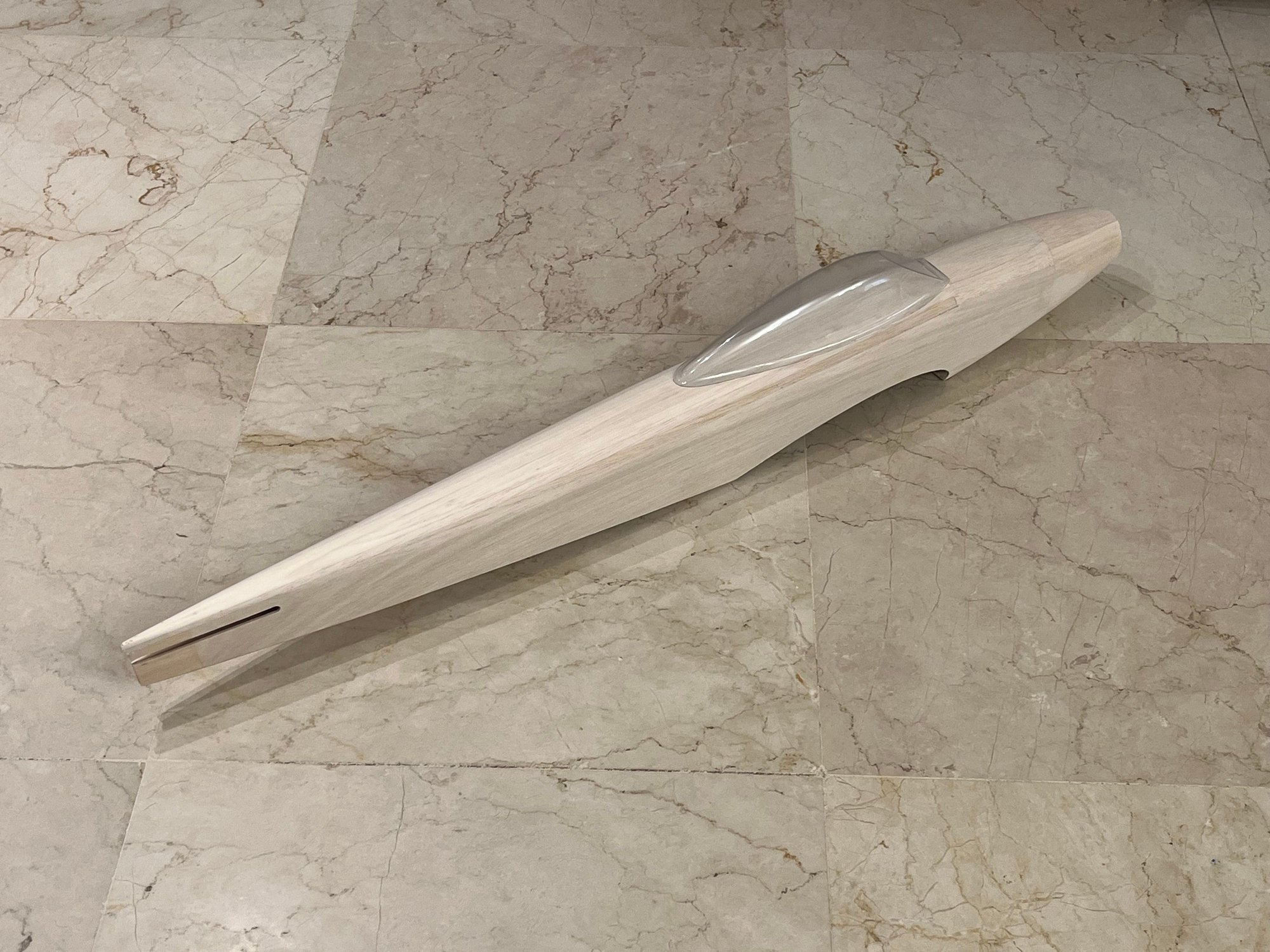
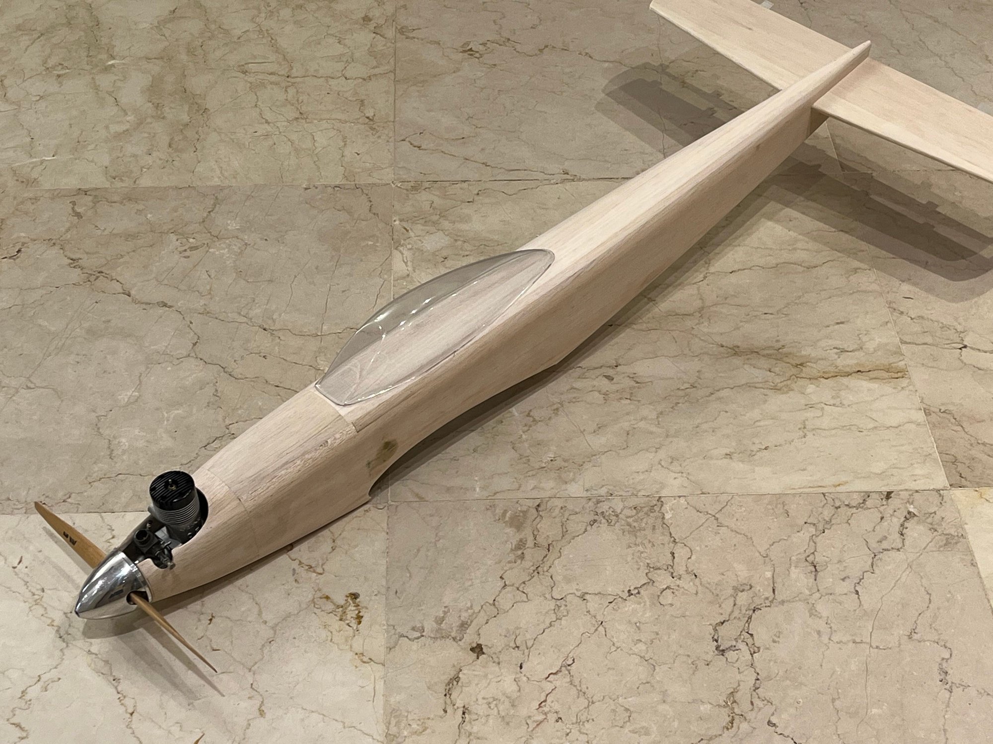
By the way, I�m also posting a few photos of the fuselage shaping process. The airplane�s form is now starting to emerge, and you can finally see what it will look like.
Best regards,
Ehsan
Thank you very much for your kind and heartfelt message.
The art of model building is a shared language and a common passion that transcends political and geographical boundaries, bringing people closer together.
I hope the day comes when I can join you and other fellow enthusiasts without any restrictions, so that we can enjoy working on and flying our model airplanes together. And I hope that one day you will also be able to visit us without any limitations and be our guest.
Life is nothing more than these moments we share.
By the way, I�m also posting a few photos of the fuselage shaping process. The airplane�s form is now starting to emerge, and you can finally see what it will look like.
Best regards,
Ehsan

 06-01-2026 | 10:33 AM
#18
She is shaping along nicely. Very pretty lines. And looks very good wearing that O&S engine in the front.