


OS 50cc Gemini Twin Gasoline Conversion
 02-23-2023, 06:36 AM
#51
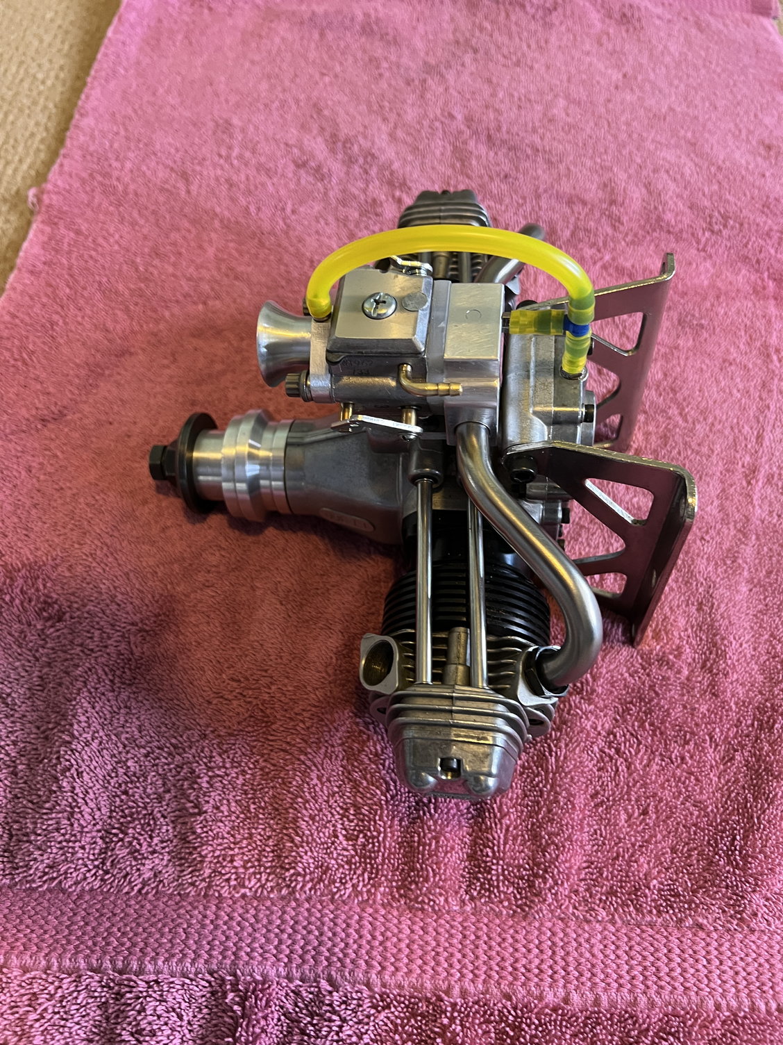
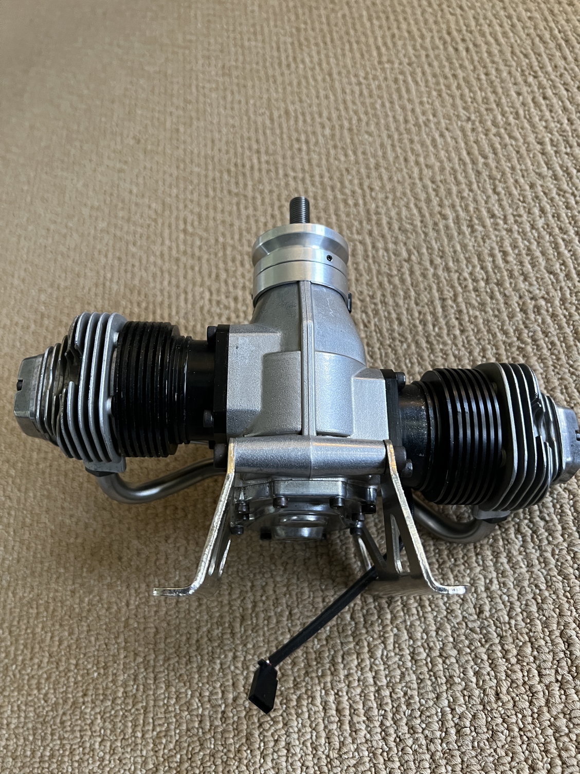
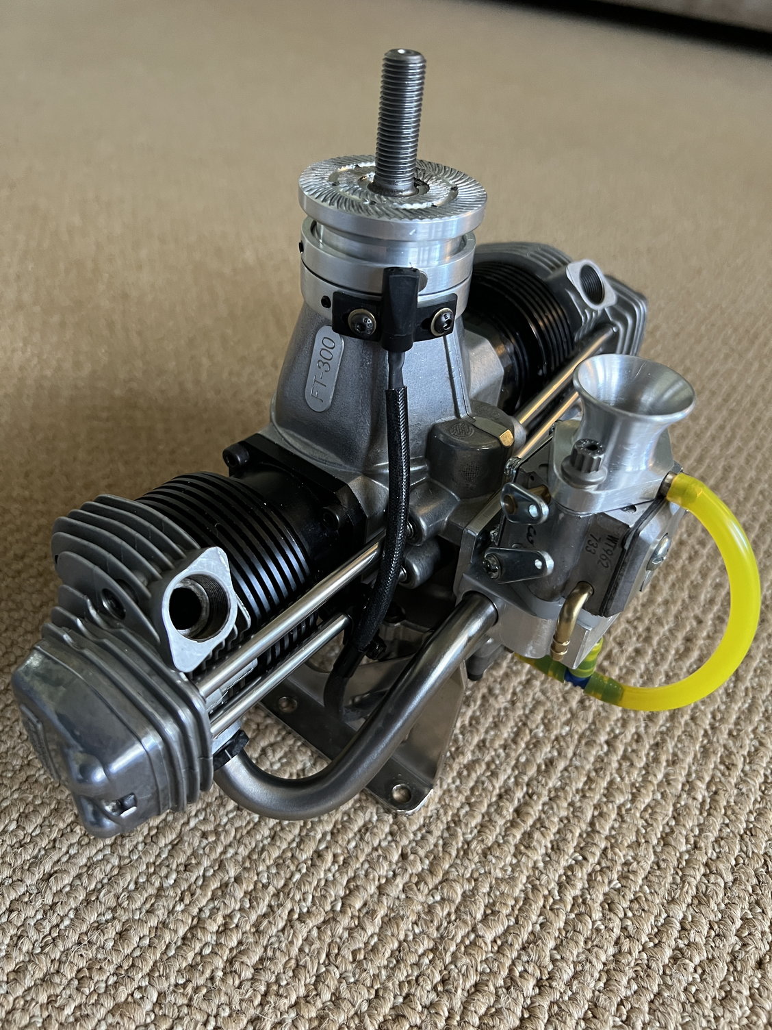
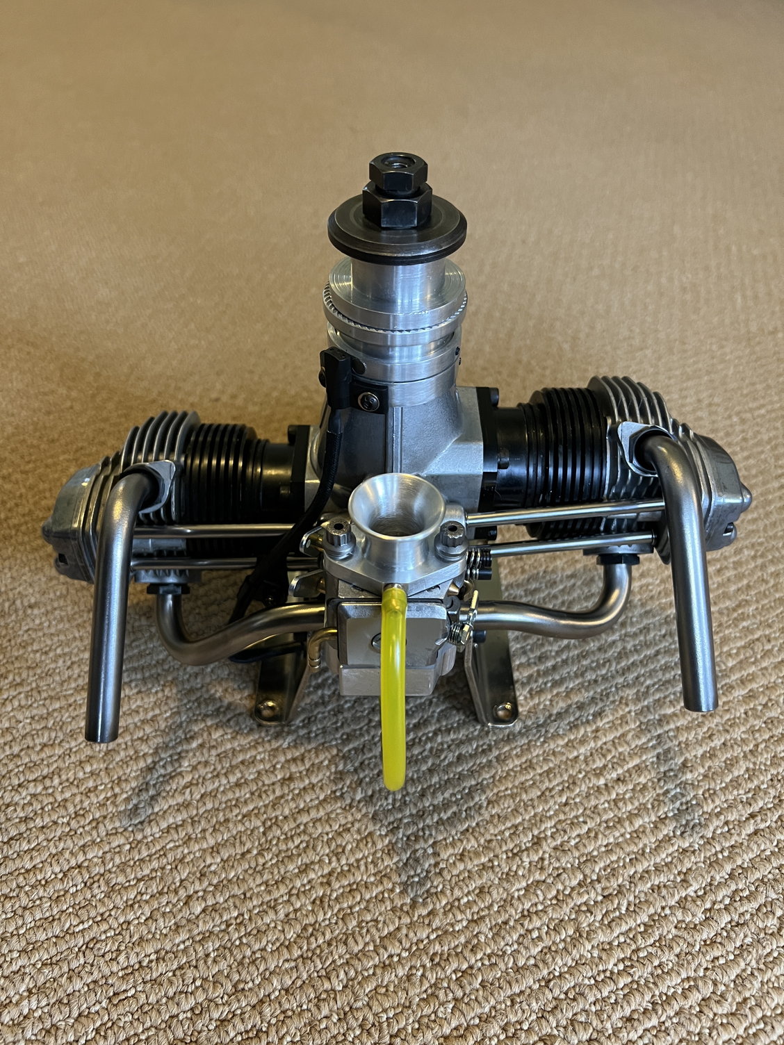
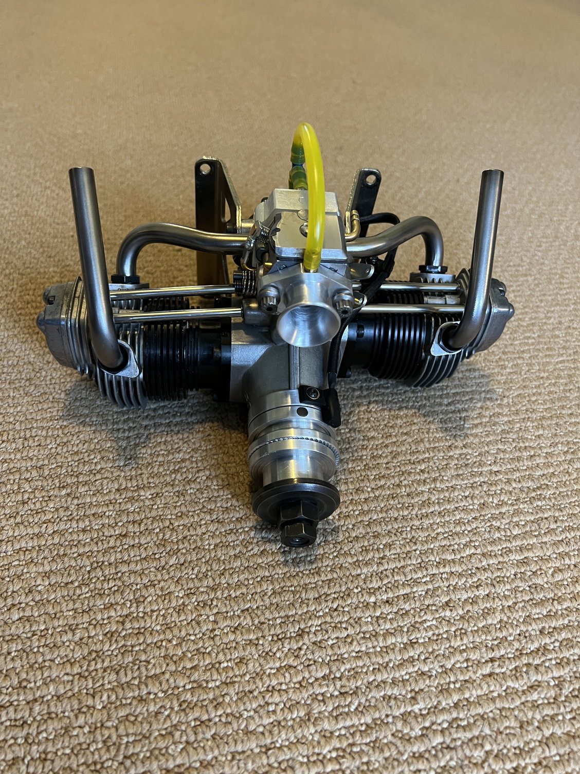
So here it is with the induction system completed. I relocated the pressure-pulse nipple on the intake manifold to face backwards for reasons you will see in the last shot. The whole project came out better than I could've hoped. I'm almost sorry it's (almost) over. I had been looking forward to this for a LONG time.
Now I have to incorporate the ignition components then test run.
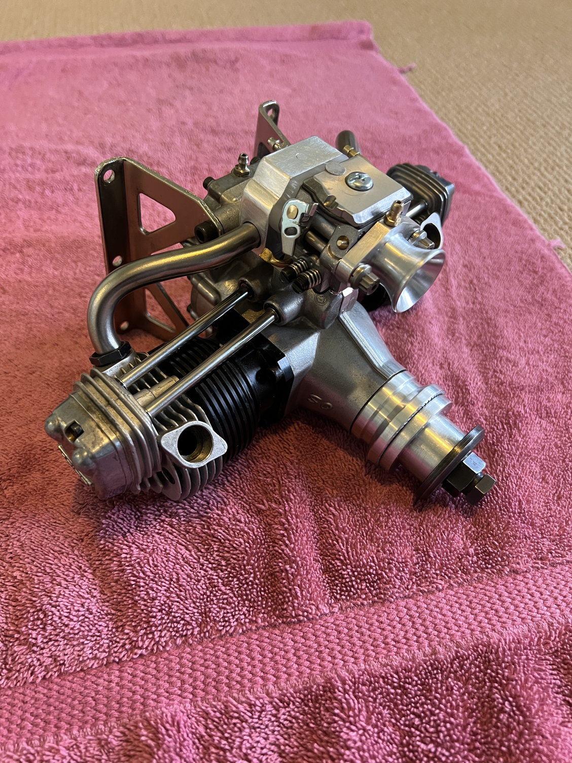
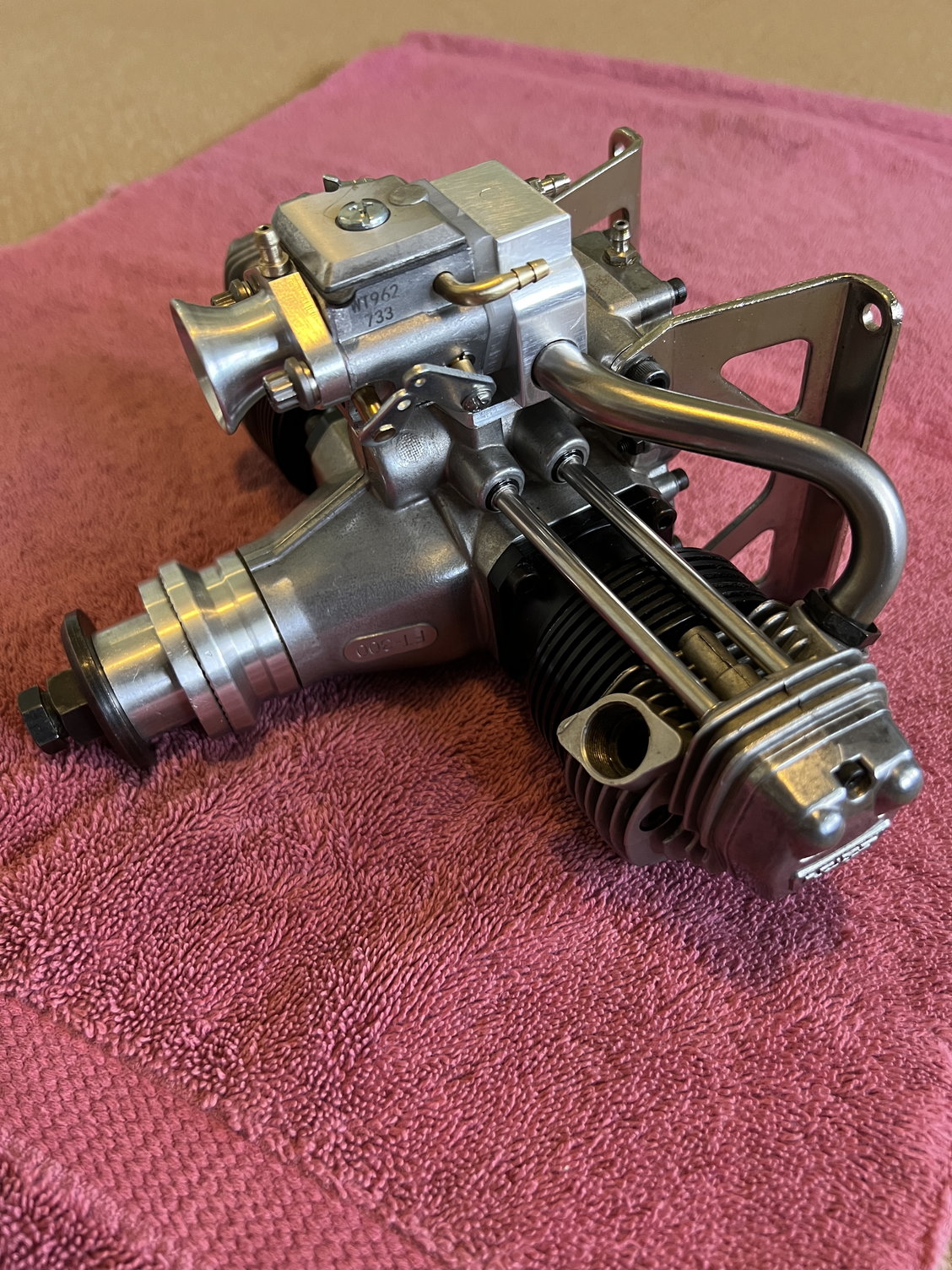
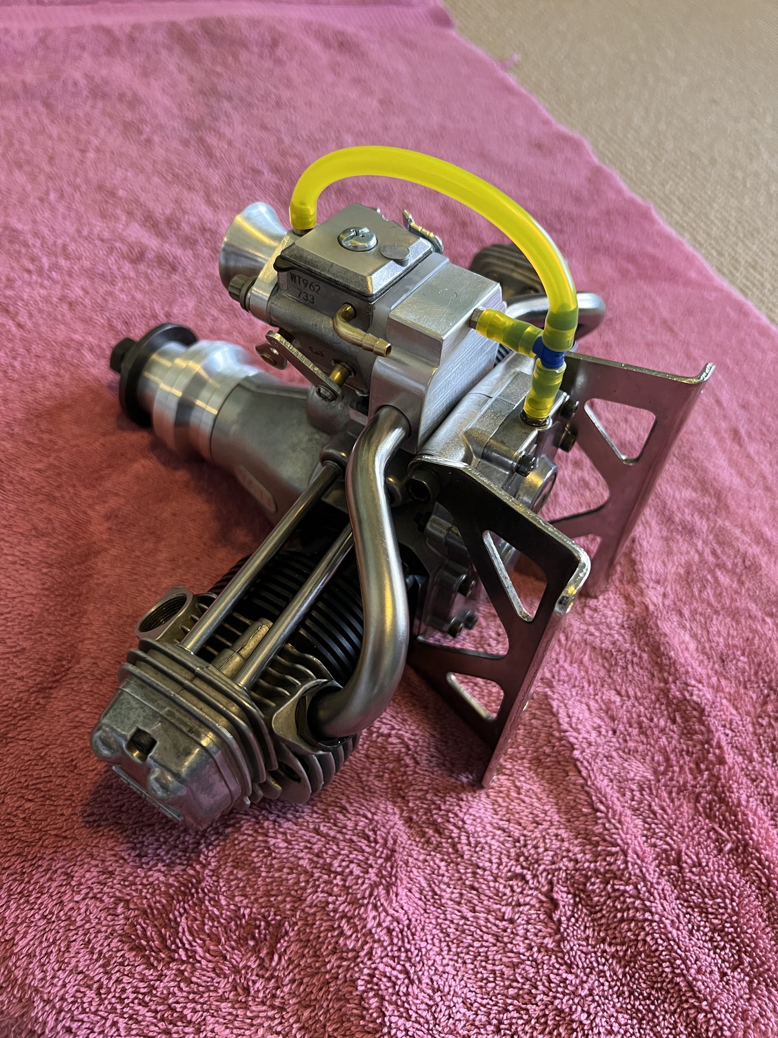
Pressure pulse exits the crankcase straight into the manifold pressure port while waste oil heads to the intake venturi for recycling. Neat and clean.
What a jewel.
Now I have to incorporate the ignition components then test run.
Pressure pulse exits the crankcase straight into the manifold pressure port while waste oil heads to the intake venturi for recycling. Neat and clean.
What a jewel.
Last edited by mitchilito; 02-23-2023 at 03:37 PM.

 02-23-2023, 03:47 PM
#53
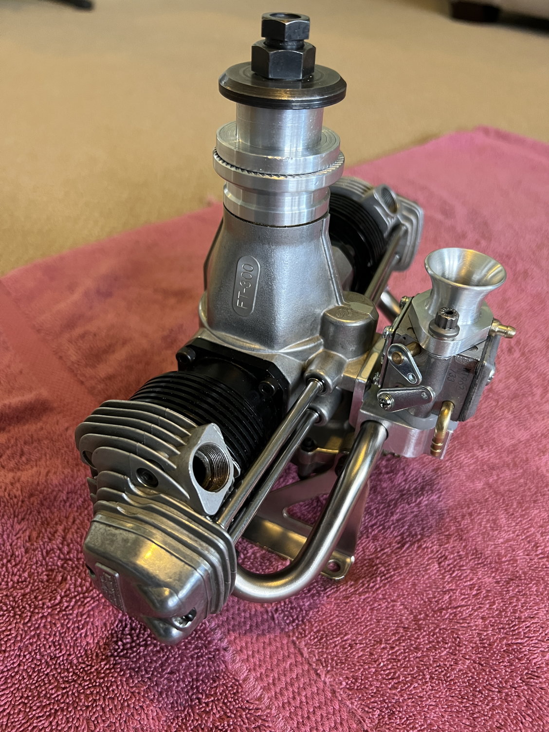
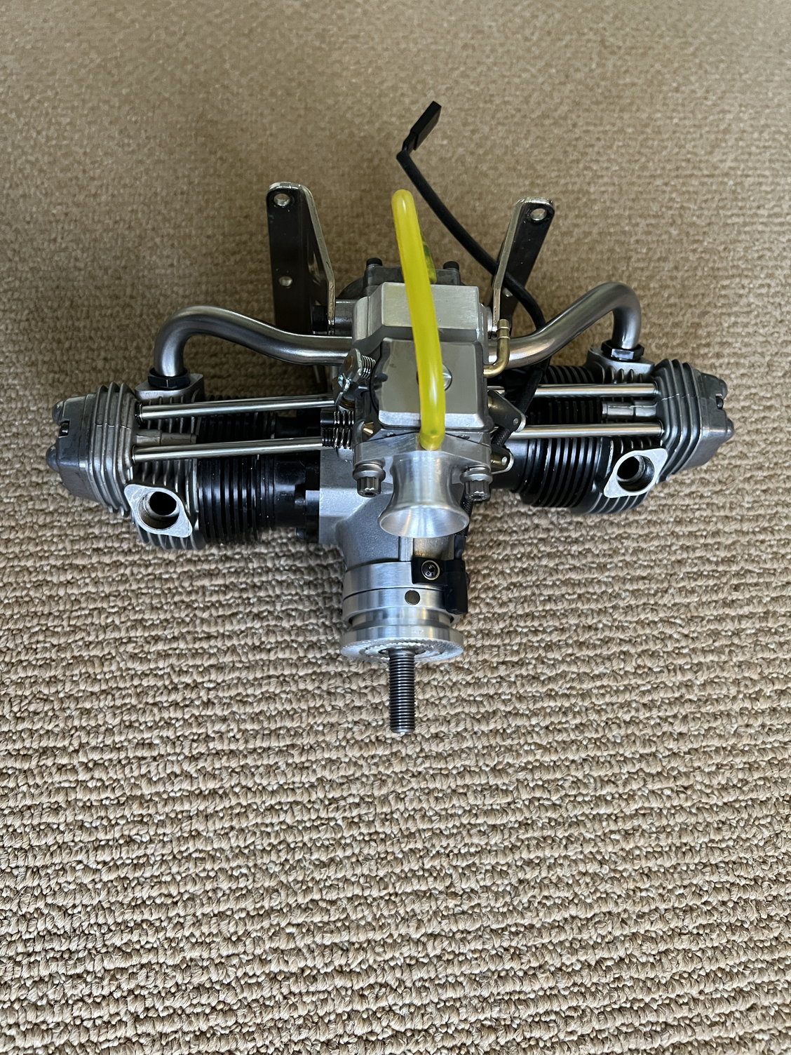
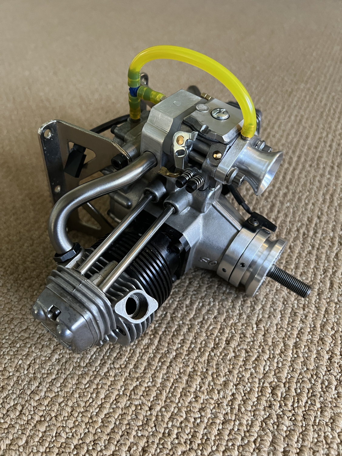
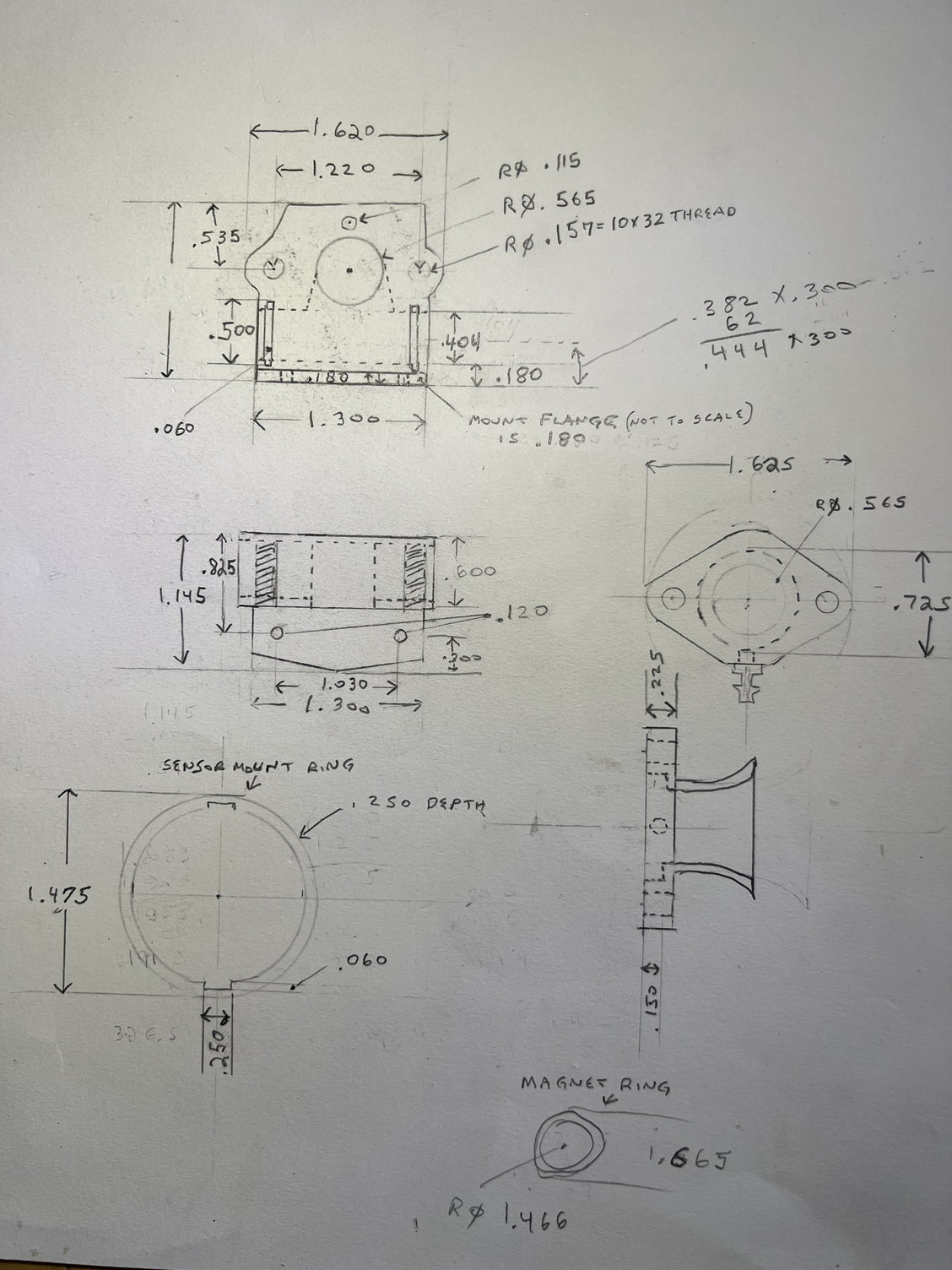
I spent the latter part of the day knocking out the ignition components. These were a LOT easier than the manifold and venturi. So this concluded all the required parts for gas conversion.

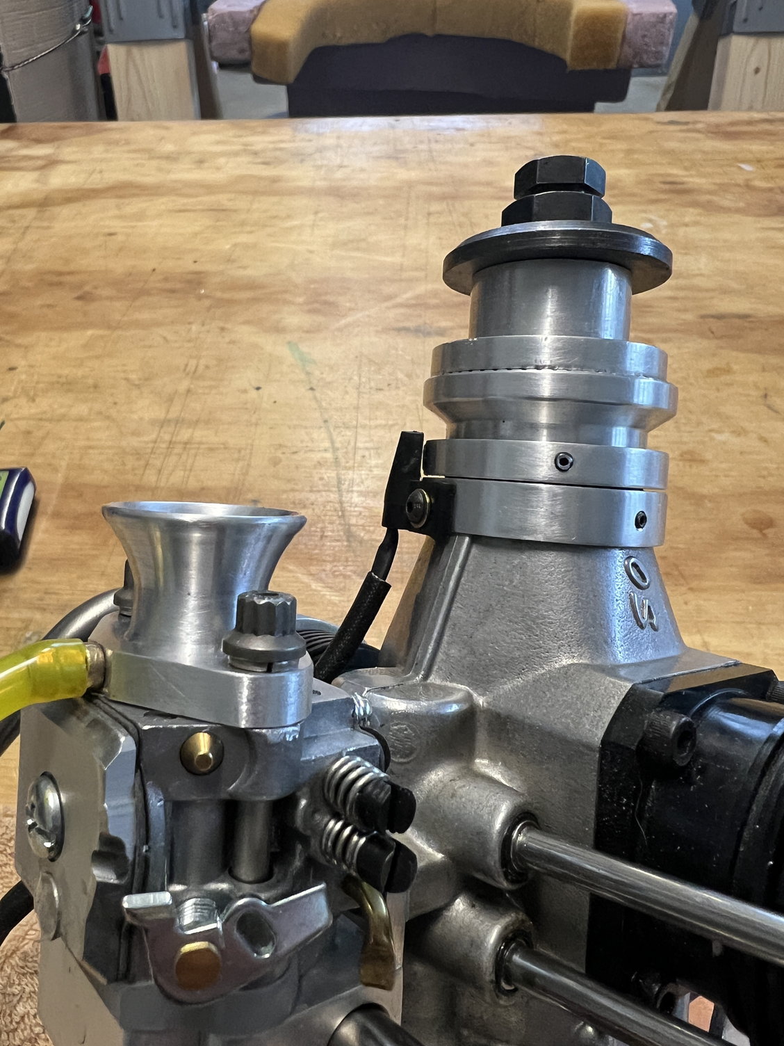
Ring on the left is the mount for the timing sensor and mounts to crankcase. Ring on the right mounts to prop hub and has the magnet mounted in it.
 02-24-2023, 05:26 AM
#55
A pro look on those rings, Mitch. I expected no less. 
The gap between the hall sensor and magnet may be pushing the limits? I had trouble with ignition intermitancy with a gap approx that wide using an Rcexl setup. Hopefully it works for you without issues. Keep in mind that magnets lose permeability with time and heat, so what works marginally today may not work well years later.
The gap between the hall sensor and magnet may be pushing the limits? I had trouble with ignition intermitancy with a gap approx that wide using an Rcexl setup. Hopefully it works for you without issues. Keep in mind that magnets lose permeability with time and heat, so what works marginally today may not work well years later.
02-24-2023, 02:38 PM
#56
A pro look on those rings, Mitch. I expected no less.
The gap between the hall sensor and magnet may be pushing the limits? I had trouble with ignition intermitancy with a gap approx that wide using an Rcexl setup. Hopefully it works for you without issues. Keep in mind that magnets lose permeability with time and heat, so what works marginally today may not work well years later.
The gap between the hall sensor and magnet may be pushing the limits? I had trouble with ignition intermitancy with a gap approx that wide using an Rcexl setup. Hopefully it works for you without issues. Keep in mind that magnets lose permeability with time and heat, so what works marginally today may not work well years later.
Yeah, the gap turned out a little bigger than I wanted. I might have to take some action later on.
I have several hall chips kicking around and I might machine a mount out of billet that sits much closer. Right now it sparks like crazy.
02-24-2023, 03:18 PM
#57
Thanks for the keen observation, GG!
Yeah, the gap turned out a little bigger than I wanted. I might have to take some action later on.
I have several hall chips kicking around and I might machine a mount out of billet that sits much closer. Right now it sparks like crazy.
Yeah, the gap turned out a little bigger than I wanted. I might have to take some action later on.
I have several hall chips kicking around and I might machine a mount out of billet that sits much closer. Right now it sparks like crazy.
Most of these CDI's, Rcxel and CH for sure, are sitting there when powered up ready to spark at full advance. It's not until the CDI detects rpm, on prop flip, that it retards the timing for start up. If the hall effect sensor misses that first low rpm signal it may, not saying it will, fire at full advance. I'm not sure if that would cause the prop to kick back or not but "better safe than sorry" is a rule I give considerable weighting to.
Last edited by Glowgeek; 02-24-2023 at 03:22 PM.
02-25-2023, 03:19 AM
#58
No problem, just don't want your fingers to get whacked.
Most of these CDI's, Rcxel and CH for sure, are sitting there when powered up ready to spark at full advance. It's not until the CDI detects rpm, on prop flip, that it retards the timing for start up. If the hall effect sensor misses that first low rpm signal it may, not saying it will, fire at full advance. I'm not sure if that would cause the prop to kick back or not but "better safe than sorry" is a rule I give considerable weighting to.
Most of these CDI's, Rcxel and CH for sure, are sitting there when powered up ready to spark at full advance. It's not until the CDI detects rpm, on prop flip, that it retards the timing for start up. If the hall effect sensor misses that first low rpm signal it may, not saying it will, fire at full advance. I'm not sure if that would cause the prop to kick back or not but "better safe than sorry" is a rule I give considerable weighting to.
02-25-2023, 08:39 AM
#60
I can't tell you what to do Tony, but I will say this, if that Roto 85 was mine I would certainly recirculate the waste oil.
Last edited by mitchilito; 02-26-2023 at 02:57 AM.
02-25-2023, 08:43 AM
#61
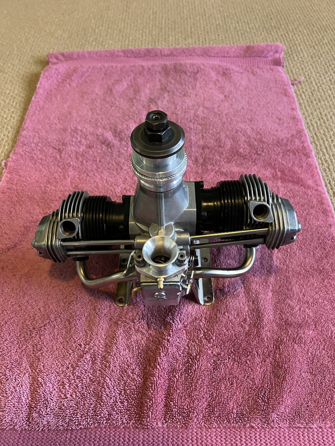
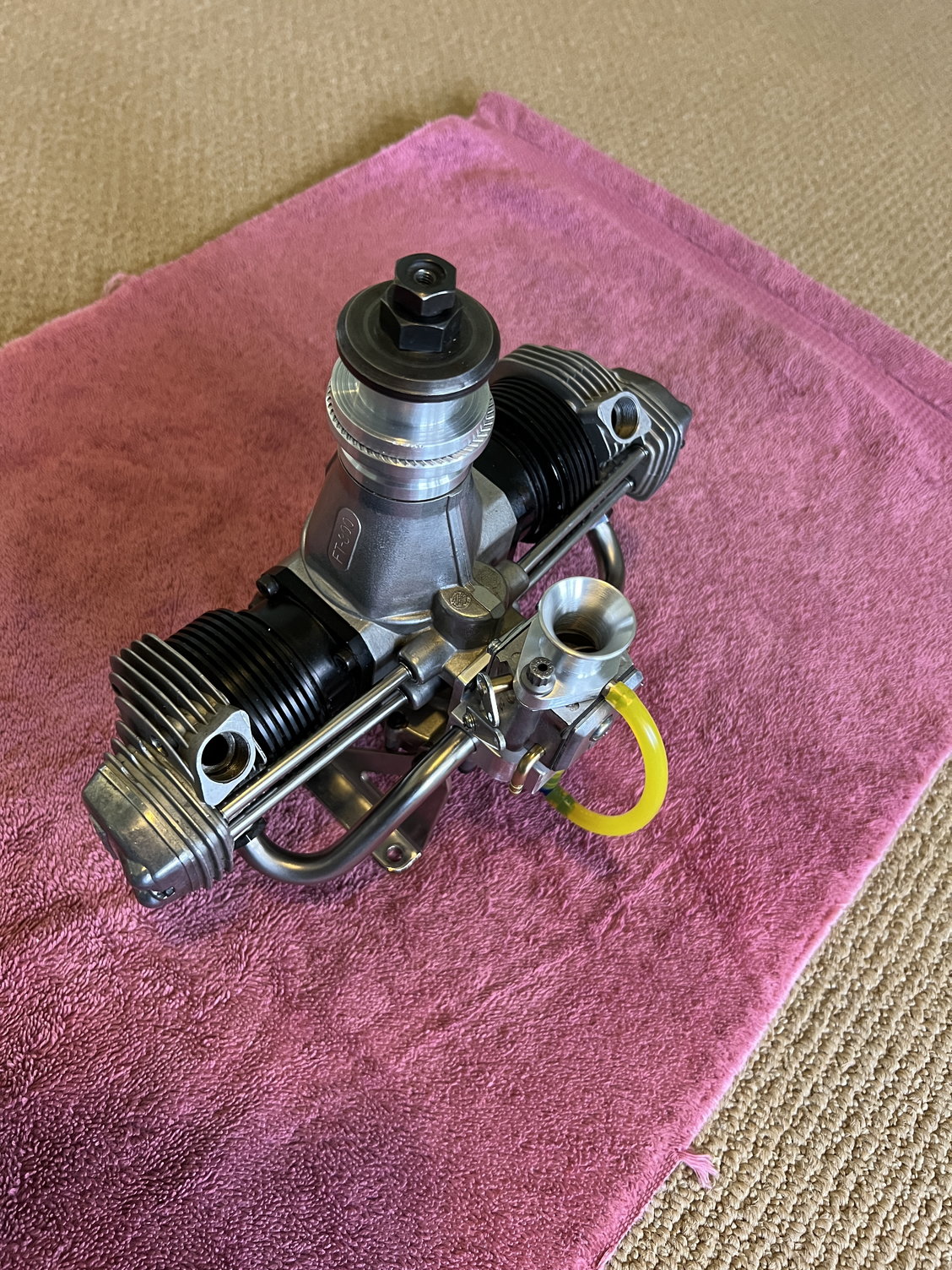
The final step is to make some new exhaust tubes. When I got the engine one tube was bad. Also, I like a slightly longer tube than stock.
At the bottom we see the completed engine. It has been a lot of fun and I might be a little sad it's done. But I do get to run it now
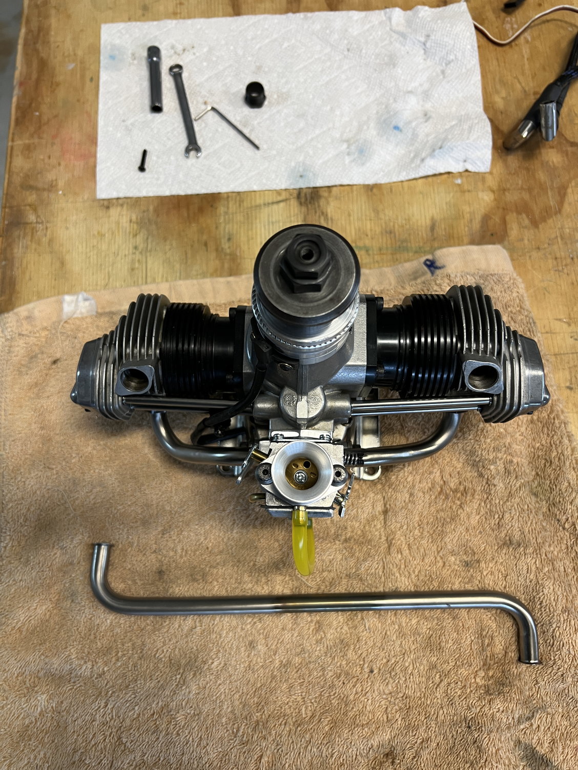
Just need to be cut.
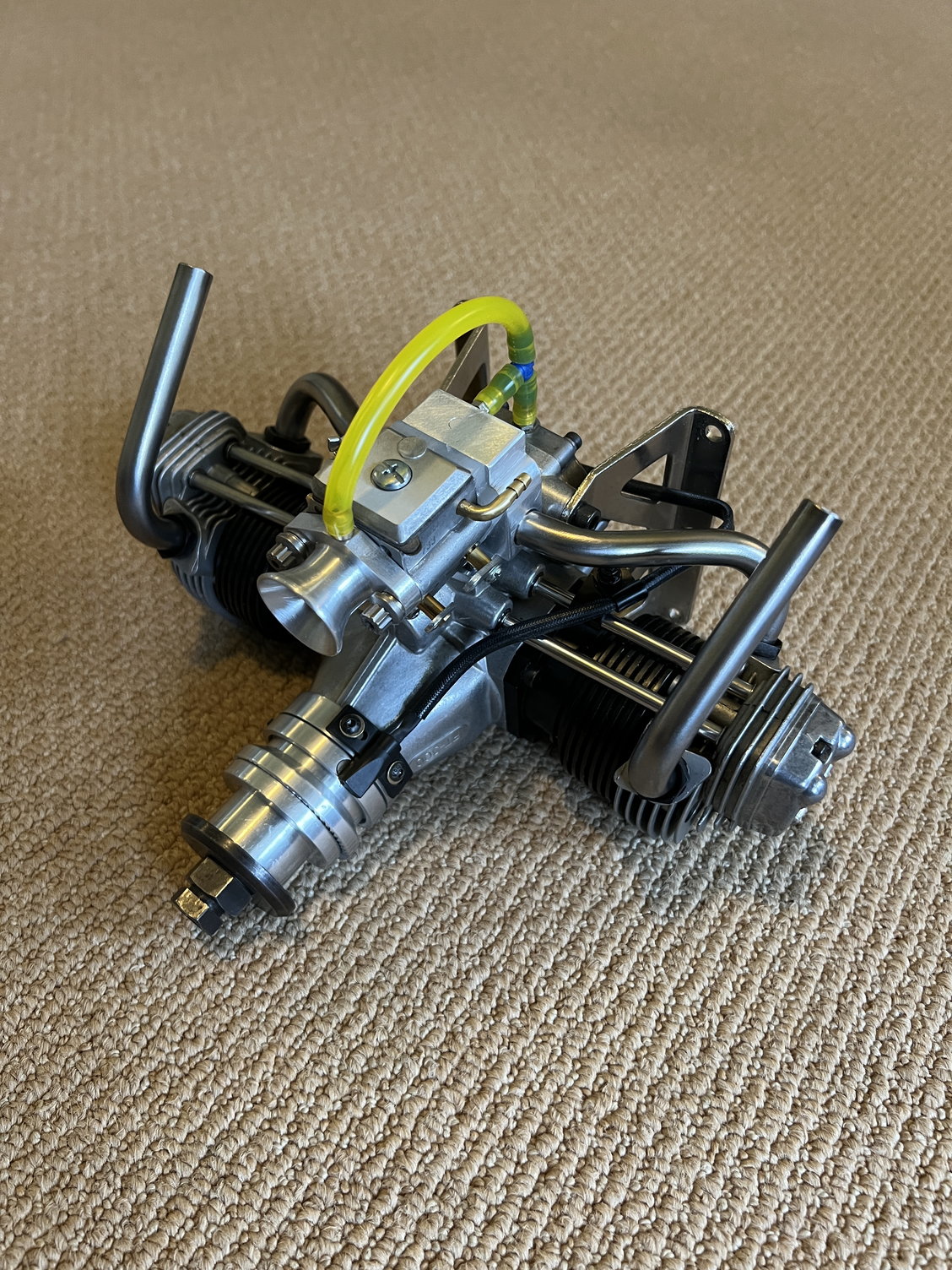 Ready to run!
At the bottom we see the completed engine. It has been a lot of fun and I might be a little sad it's done. But I do get to run it now
Just need to be cut.
Ready to run!Last edited by mitchilito; 02-25-2023 at 01:53 PM.
The following users liked this post:
ferincr (04-11-2023)

The following users liked this post:
ferincr (04-11-2023)
02-25-2023, 02:00 PM
#65
I will be installing a 20x8 prop. The gas conversion robs 10 or 15% of the power when compared to the Nitro powered version. For me, this engine doesn't need to be a crazy powerhouse. I will be designing an airframe that works best with its power to weight ratio. Right now, I'm planning a biplane version of the Sig Rascal (like I have my 25cc Gemini in) only bigger to suit this 50cc engine. Only time will tell. . ..
Last edited by mitchilito; 02-25-2023 at 02:07 PM.
02-26-2023, 04:28 AM
#67
I will be installing a 20x8 prop. The gas conversion robs 10 or 15% of the power when compared to the Nitro powered version. For me, this engine doesn't need to be a crazy powerhouse. I will be designing an airframe that works best with its power to weight ratio. Right now, I'm planning a biplane version of the Sig Rascal (like I have my 25cc Gemini in) only bigger to suit this 50cc engine. Only time will tell. . ..
Adrian at CH is getting 7000 with a Xoar 21x8.
Last edited by Glowgeek; 02-26-2023 at 04:42 AM.
02-27-2023, 04:21 AM
#68
I've been seeing closer to an 18% reduction in HP moving from 15% nitro to gas on my conversions. Unlike glow ignition, CDI ignition allows for additional engine loading without risk of detonation so I run the same prop as with glow, or a size bigger. This helps to keep engine rpm and temps down. I would prop that twin to 7000-7500 on the ground, whatever prop makes that happen.
Adrian at CH is getting 7000 with a Xoar 21x8.
Adrian at CH is getting 7000 with a Xoar 21x8.
 02-27-2023, 08:54 AM
#71


Join Date: Jan 2004
Location: lake in the Hills,
IL
Posts: 977
Likes: 0
Received 14 Likes
on
14 Posts
Adrian at C & H is how I got started on my Saito 180 conversion. I had been sending links to his timing video's for years. It is a combination of being cheap and liking to make my own stuff that led me to not buy one of his kits.
I found a smaller carb on fleebay and put it on the 180 yesterday and loved how it ran, thanks to this thread. The orifice is about 0.375 in a Walbro clone.
I hope we can keep these fun projects going.
Beautiful work and great pictures and info. I'm looking forward to the run video ( no pressure ).
I found a smaller carb on fleebay and put it on the 180 yesterday and loved how it ran, thanks to this thread. The orifice is about 0.375 in a Walbro clone.
I hope we can keep these fun projects going.
Beautiful work and great pictures and info. I'm looking forward to the run video ( no pressure ).
02-28-2023, 03:53 AM
#72
Adrian at C & H is how I got started on my Saito 180 conversion. I had been sending links to his timing video's for years. It is a combination of being cheap and liking to make my own stuff that led me to not buy one of his kits.
I found a smaller carb on fleebay and put it on the 180 yesterday and loved how it ran, thanks to this thread. The orifice is about 0.375 in a Walbro clone.
I hope we can keep these fun projects going.
Beautiful work and great pictures and info. I'm looking forward to the run video ( no pressure ).
I found a smaller carb on fleebay and put it on the 180 yesterday and loved how it ran, thanks to this thread. The orifice is about 0.375 in a Walbro clone.
I hope we can keep these fun projects going.
Beautiful work and great pictures and info. I'm looking forward to the run video ( no pressure ).
I've had several Saito 150/180s and as a matter of fact the 150 was the engine I first started plumbing the crankcase discharge back into the intake. As a matter of fact, as as an experiment that I did NOT think would work, I plumbed that line directly into the intake manifold (instead of plumbed to the inlet of the carb like on my Geminis) fully expecting the pressure pulse to interfere with the intake cycle. Instead, it ran like a watch and all that sludge disappeared out the exhaust. I'm not doing that on these engines out of an abundance of caution - to prevent any possibility of hydro lock. When these engines sit a long time after running the crankcase slowly dumps a LOT of oil that would just collect in the manifold - and be sucked up on first start. The singles didn't seem to collect as much after run drain oil so I didn't worry about it.
Last edited by mitchilito; 02-28-2023 at 04:00 AM.
03-01-2023, 03:32 AM
#73
I did an experiment on an OS FT120 last year just to see how much more oil would remain in the crankcase if the engine were run in the inverted position (vent facing up). In the upright mounted position (vent facing down) the crankcase retained approx 2cc of oil, in the inverted mounted position (vent facing up) approx 3cc.
Point being, if oil drainage is a concern one can either change the vent location to a higher position or run a vent line loop over the top of the engine without I'll effect.
Point being, if oil drainage is a concern one can either change the vent location to a higher position or run a vent line loop over the top of the engine without I'll effect.
Last edited by Glowgeek; 03-01-2023 at 03:52 AM.
03-01-2023, 04:26 AM
#74
I did an experiment on an OS FT120 last year just to see how much more oil would remain in the crankcase if the engine were run in the inverted position (vent facing up). In the upright mounted position (vent facing down) the crankcase retained approx 2cc of oil, in the inverted mounted position (vent facing up) approx 3cc.
Point being, if oil drainage is a concern one can either change the vent location to a higher position or run a vent line loop over the top of the engine without I'll effect.
Point being, if oil drainage is a concern one can either change the vent location to a higher position or run a vent line loop over the top of the engine without I'll effect.
03-01-2023, 04:43 AM
#75
All the nay sayers claiming the engine would load up with oil is what prompted my experiment.
In my thinking, only so much oil in liquid form could collect in the case before being whipped into a mist by the rotating assembly. Once in mist form the location of the vent becomes less relevant due to internal pumping pressure differentials. Many later model 4 strokes are vented from the top of the cam box to promote localized lubrication of that area. Some are vented near on the bottom of the cam box for the same reason.
In my thinking, only so much oil in liquid form could collect in the case before being whipped into a mist by the rotating assembly. Once in mist form the location of the vent becomes less relevant due to internal pumping pressure differentials. Many later model 4 strokes are vented from the top of the cam box to promote localized lubrication of that area. Some are vented near on the bottom of the cam box for the same reason.