Don Smith Cessna T-50


 02-27-2021, 11:20 AM
#1302
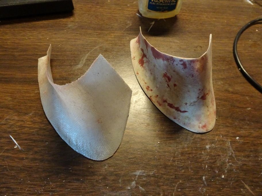
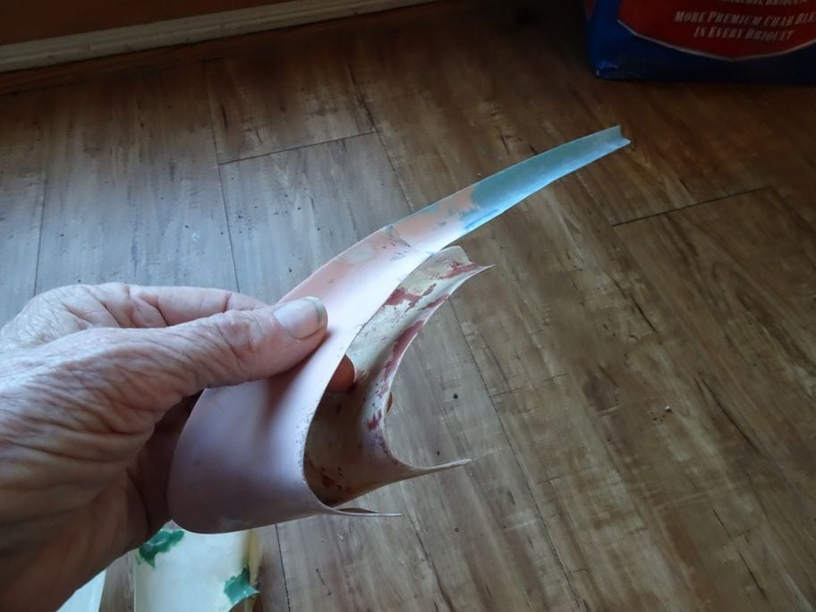
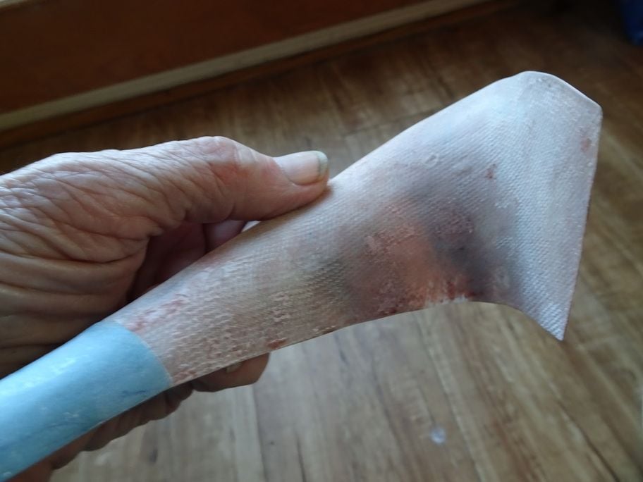
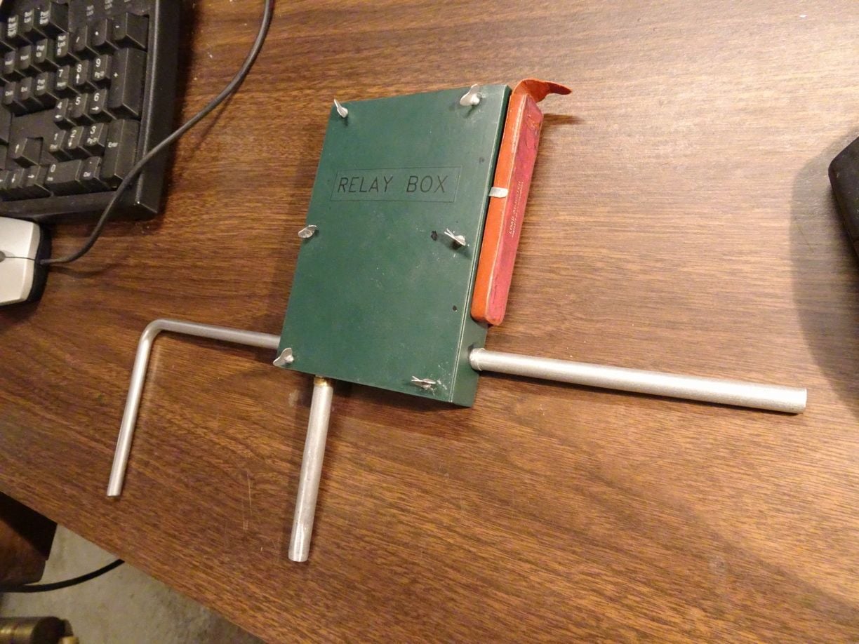
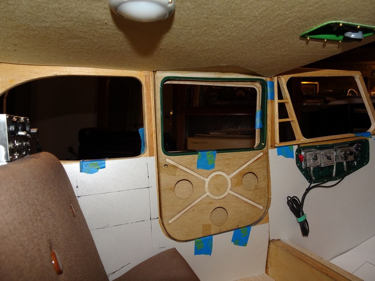
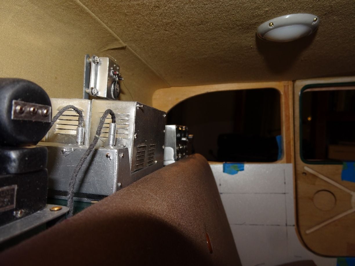
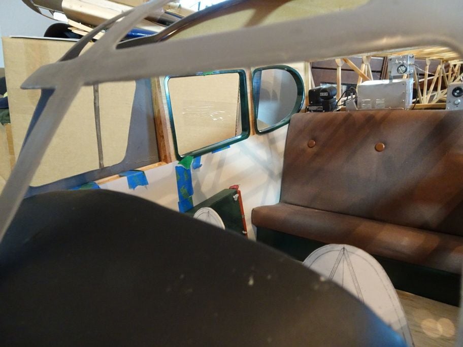
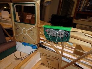
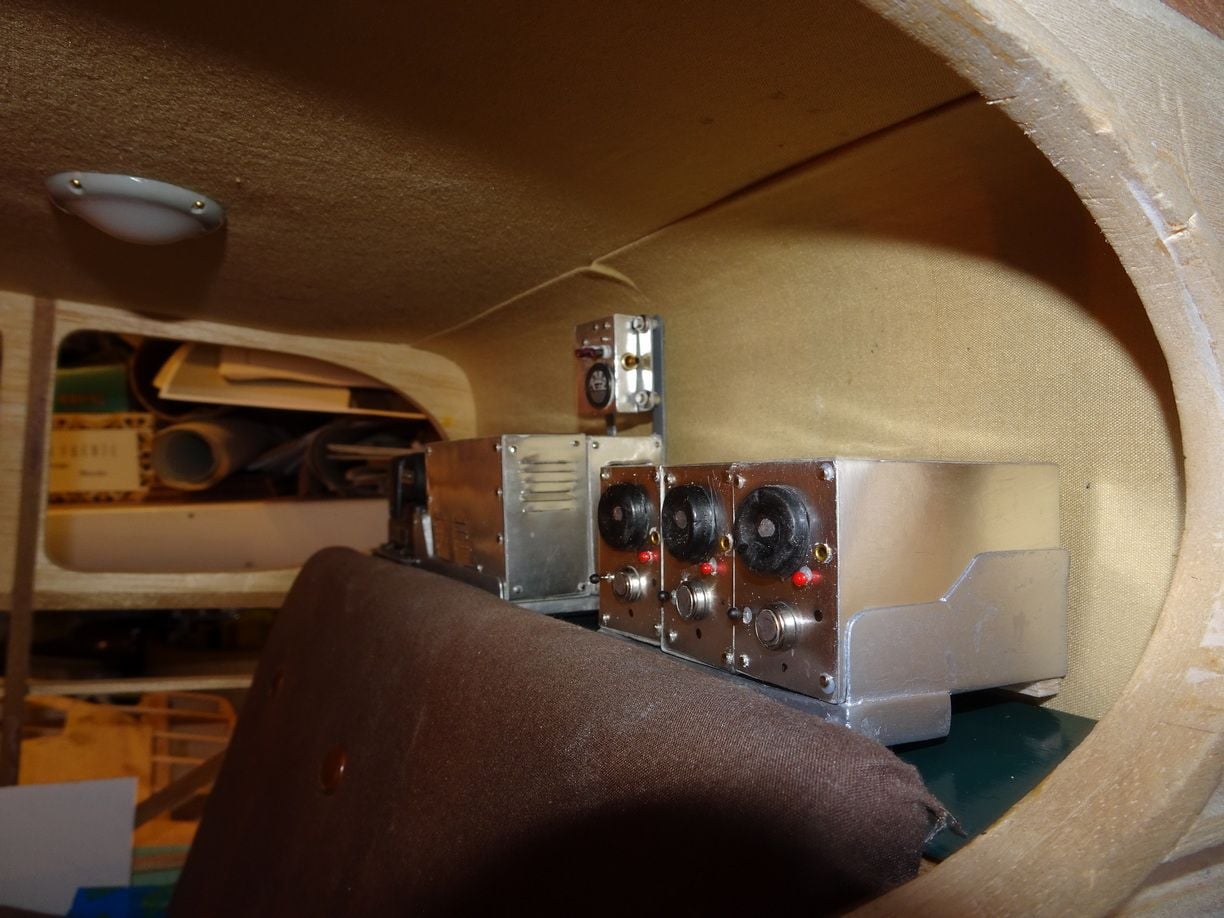
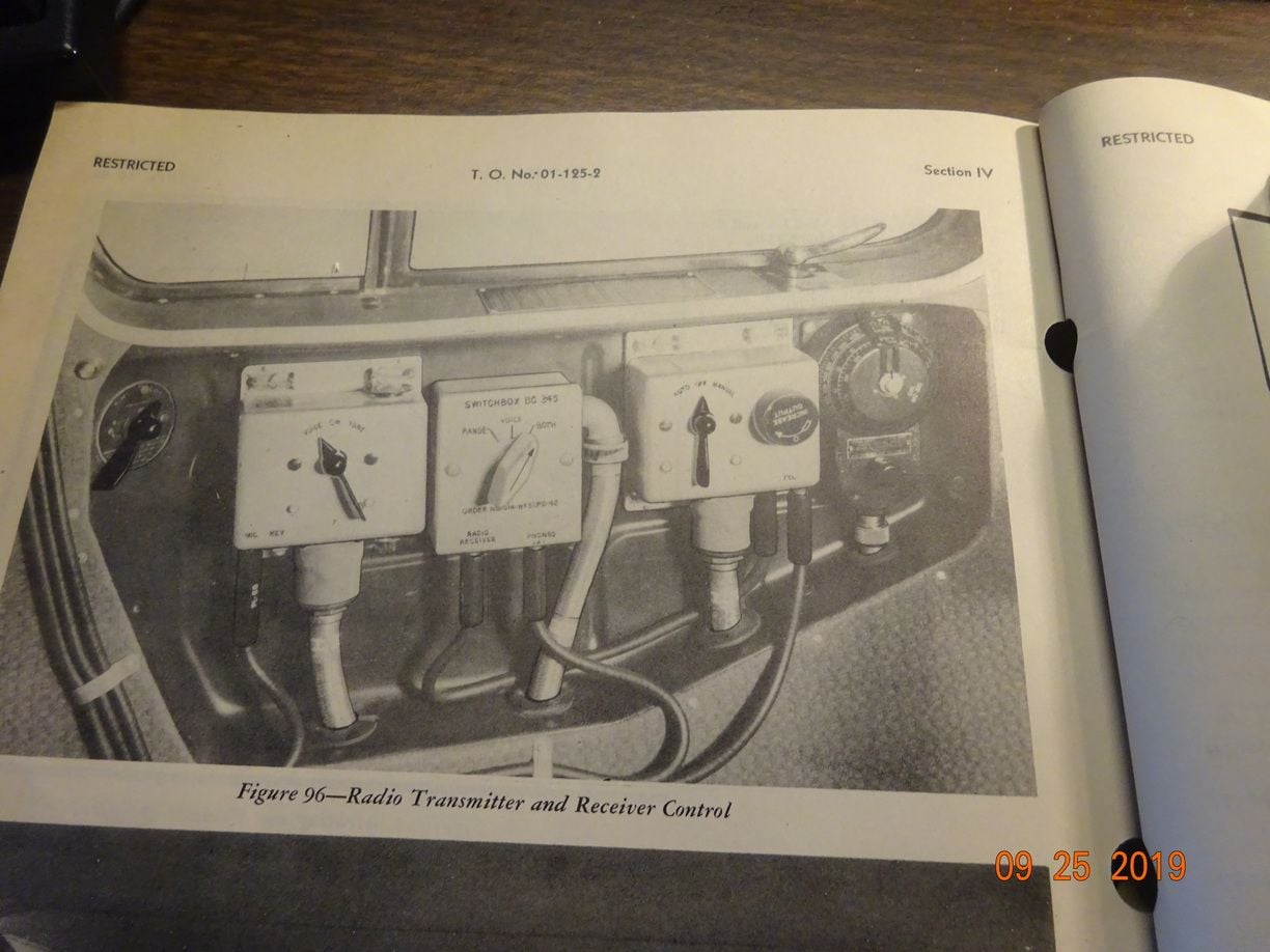
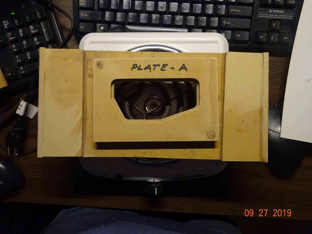
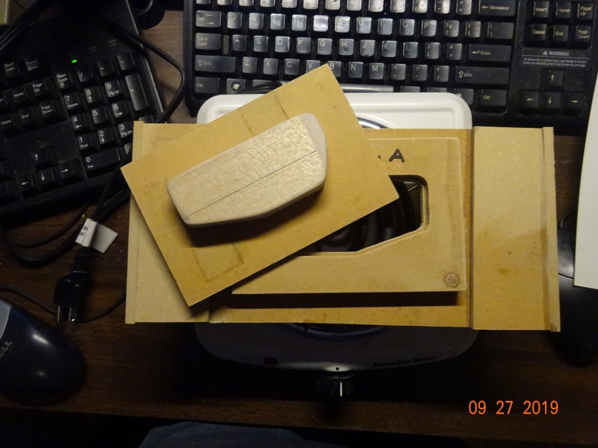
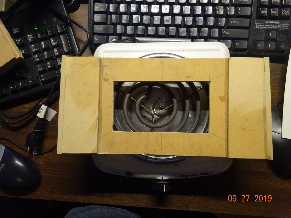
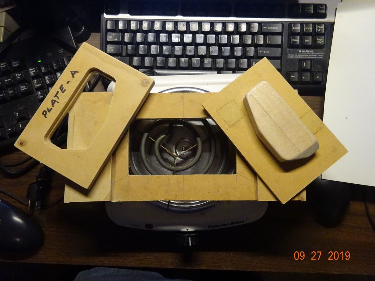
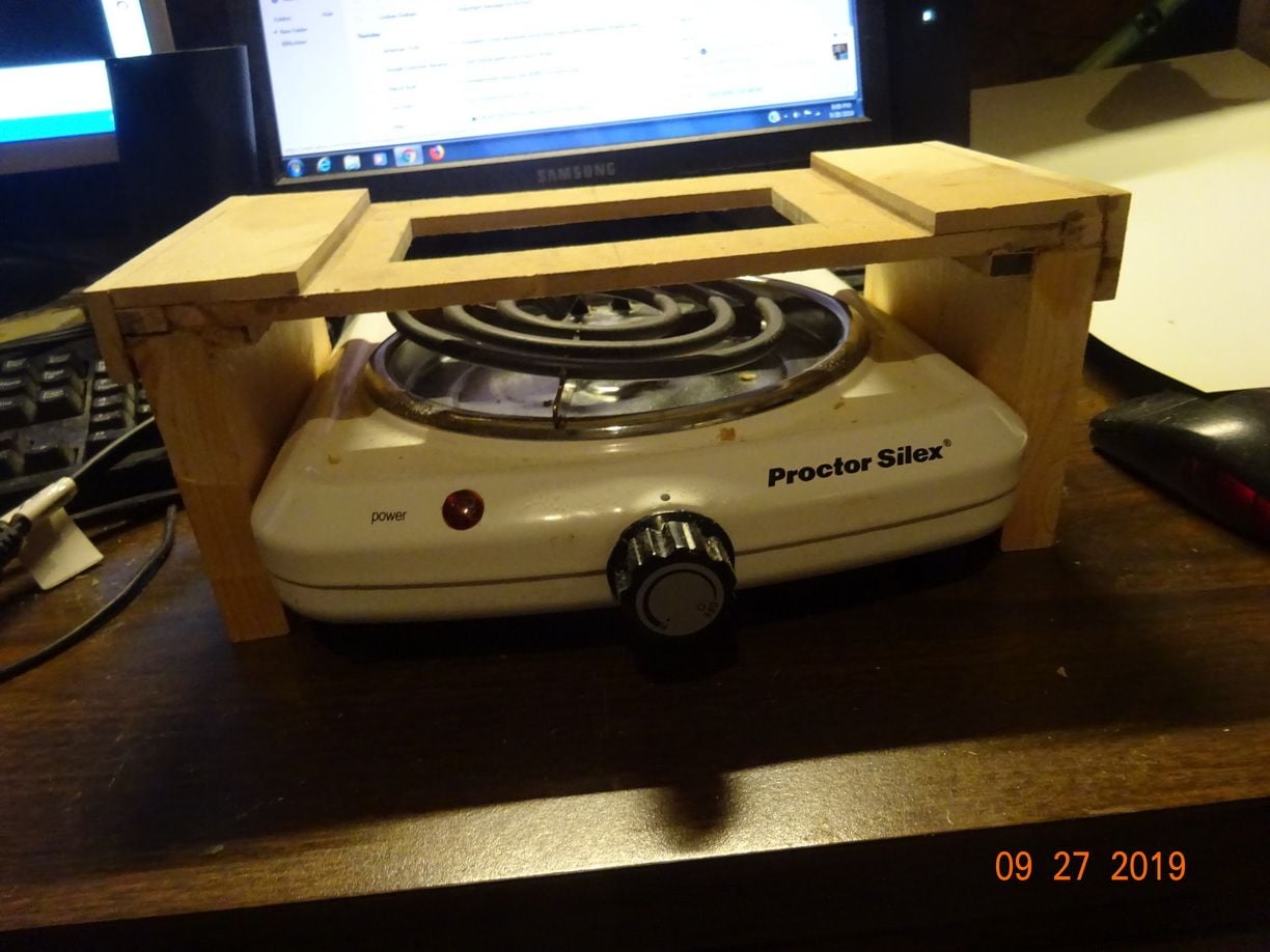
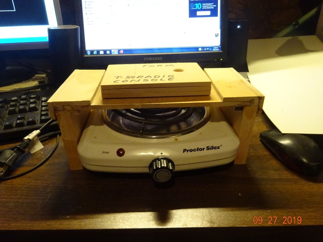
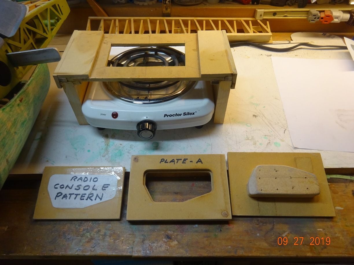
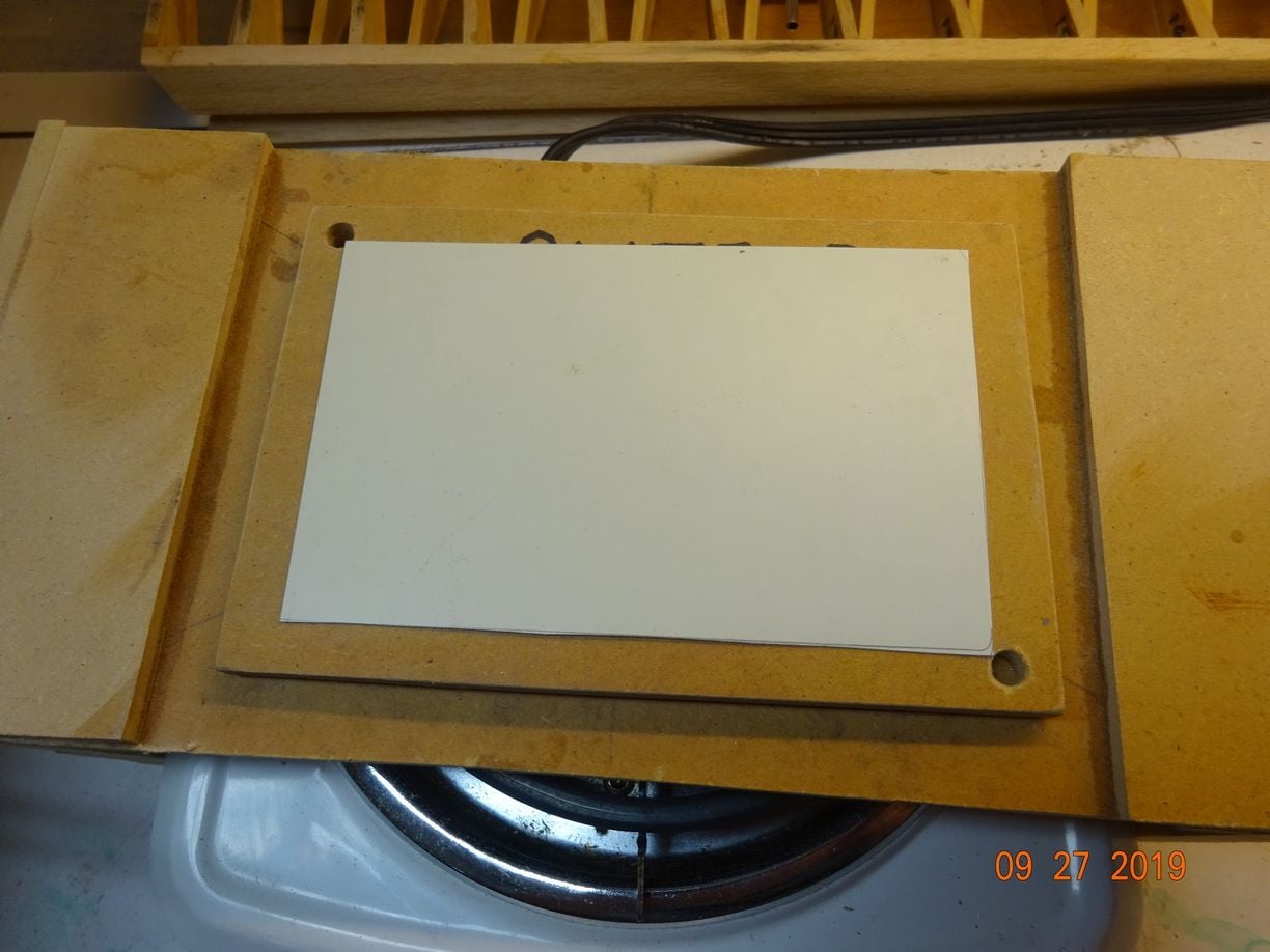
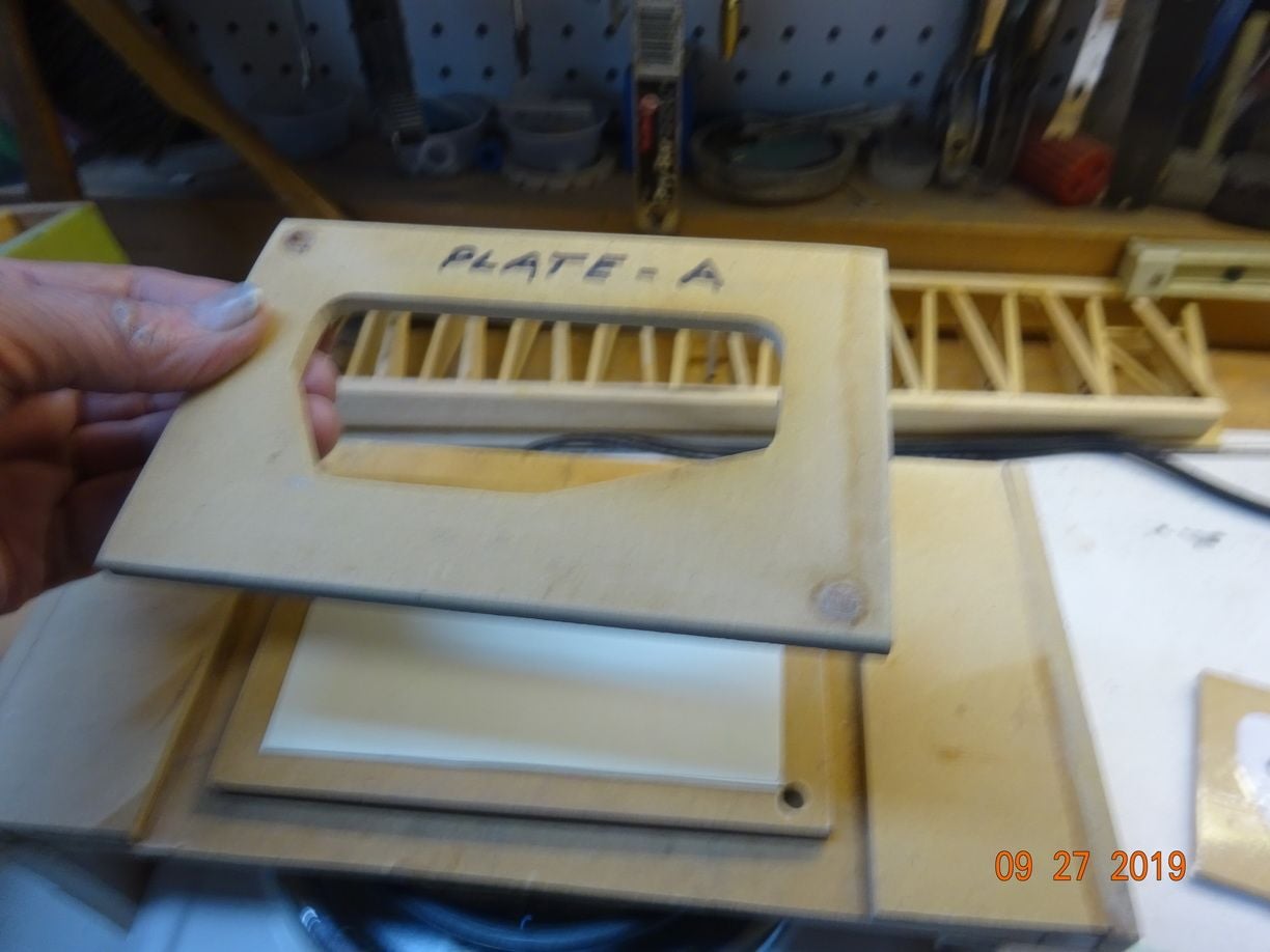
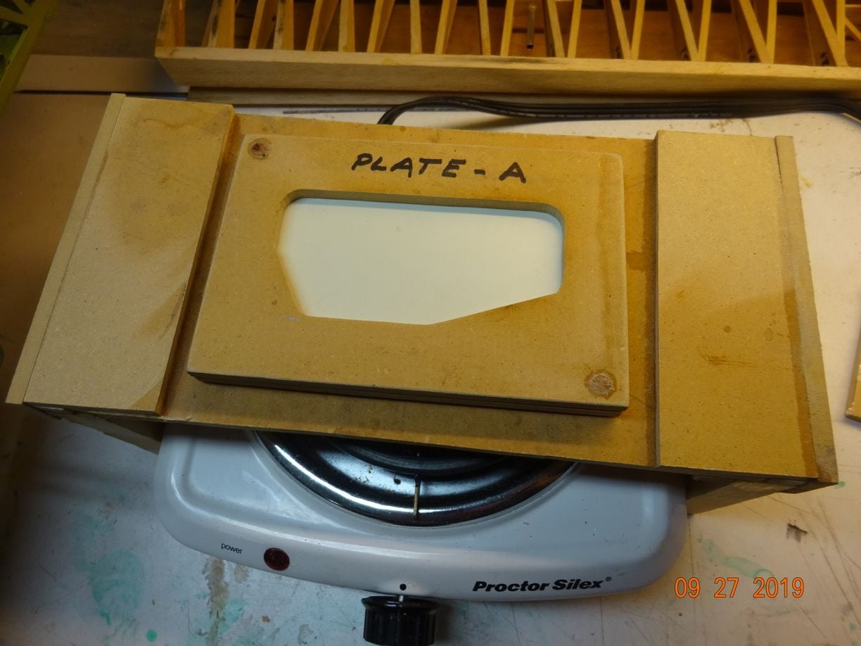
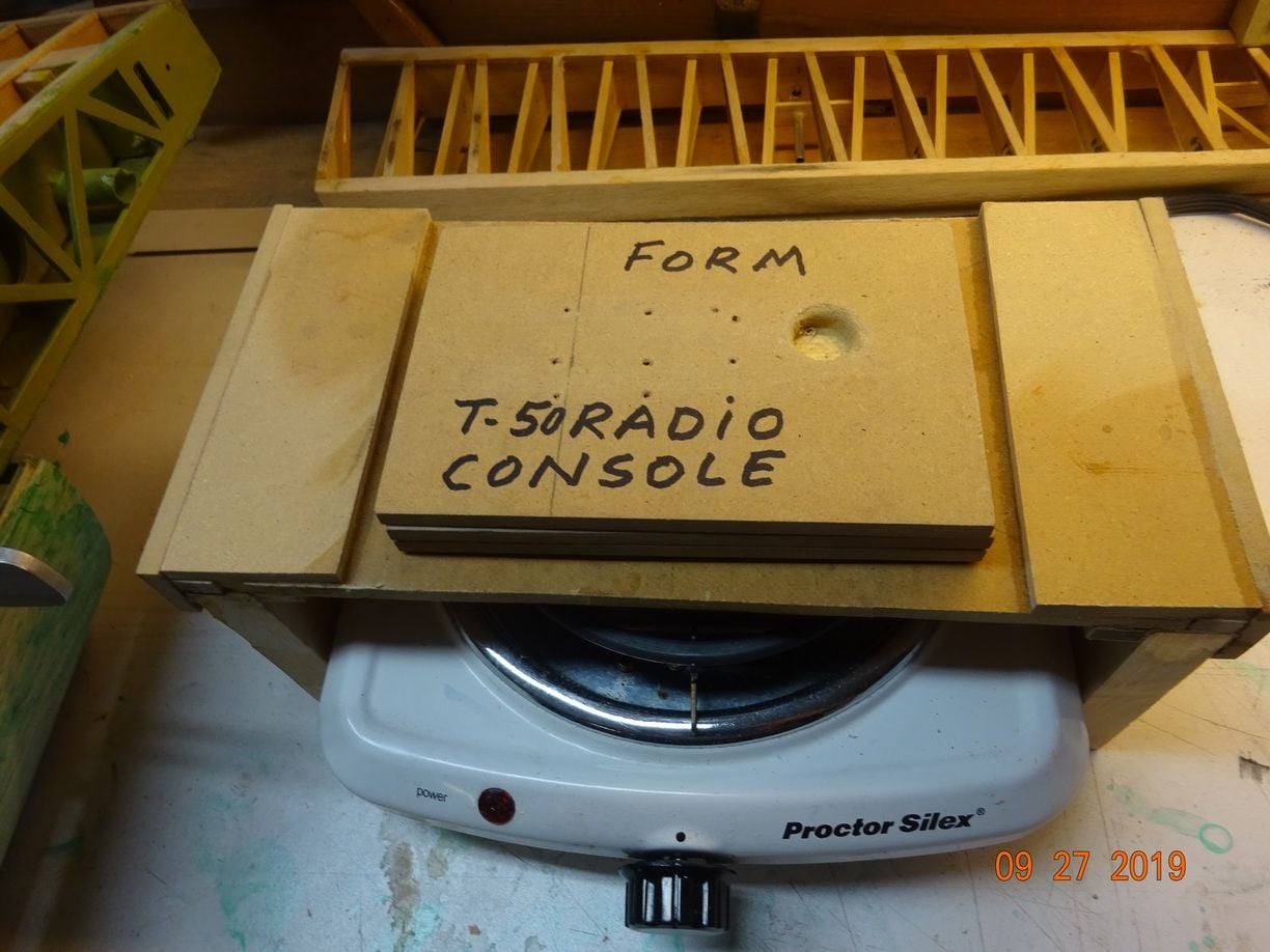
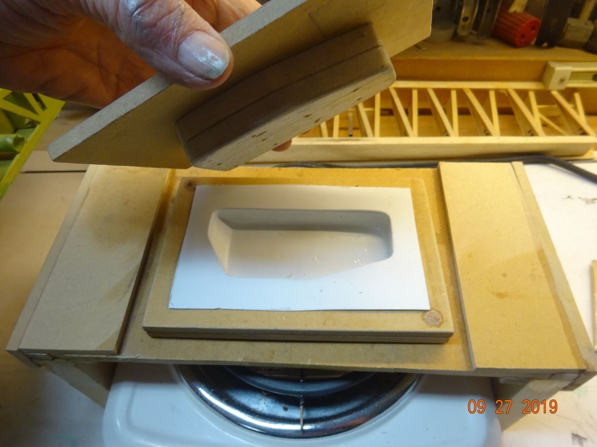
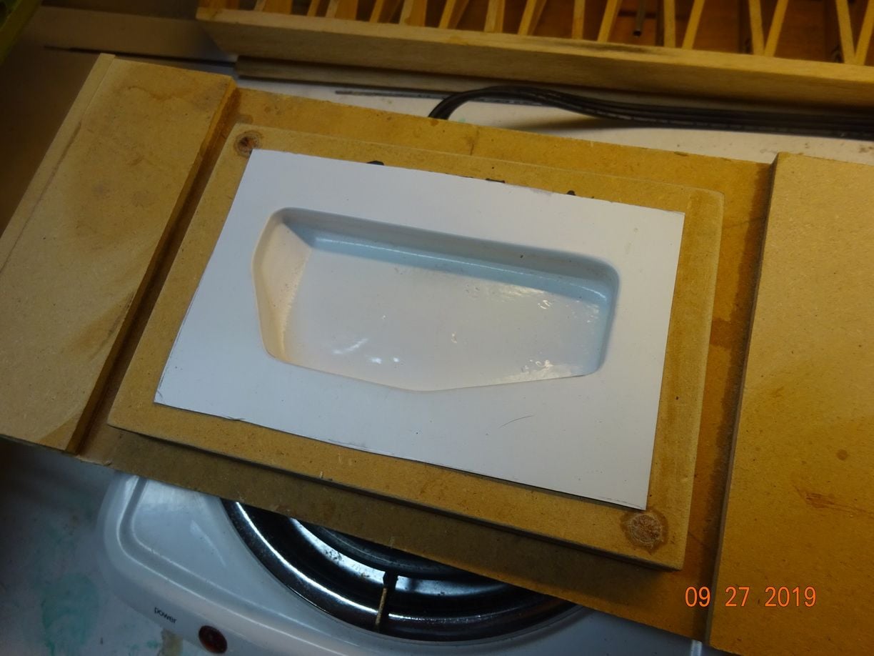
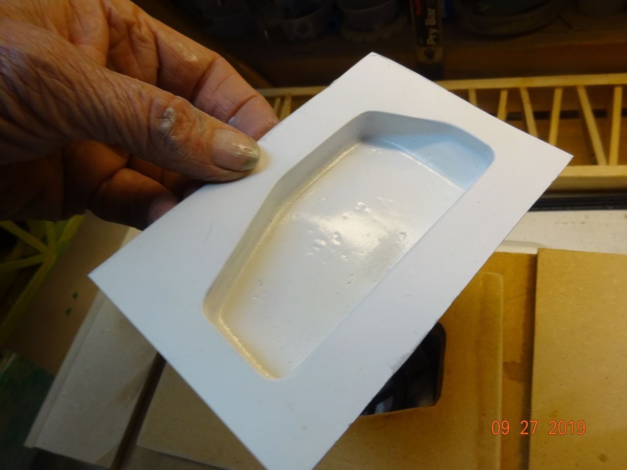
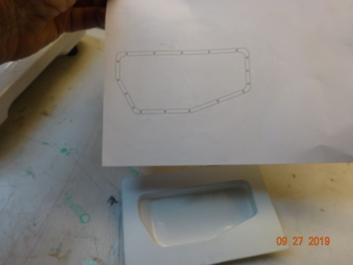
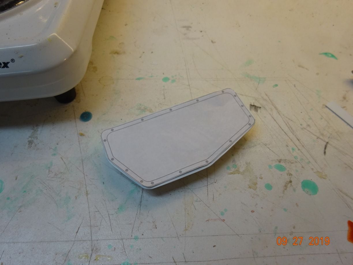
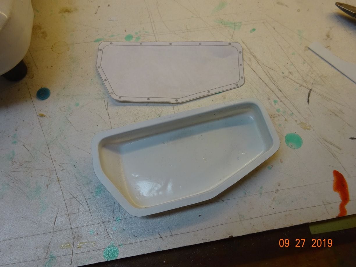
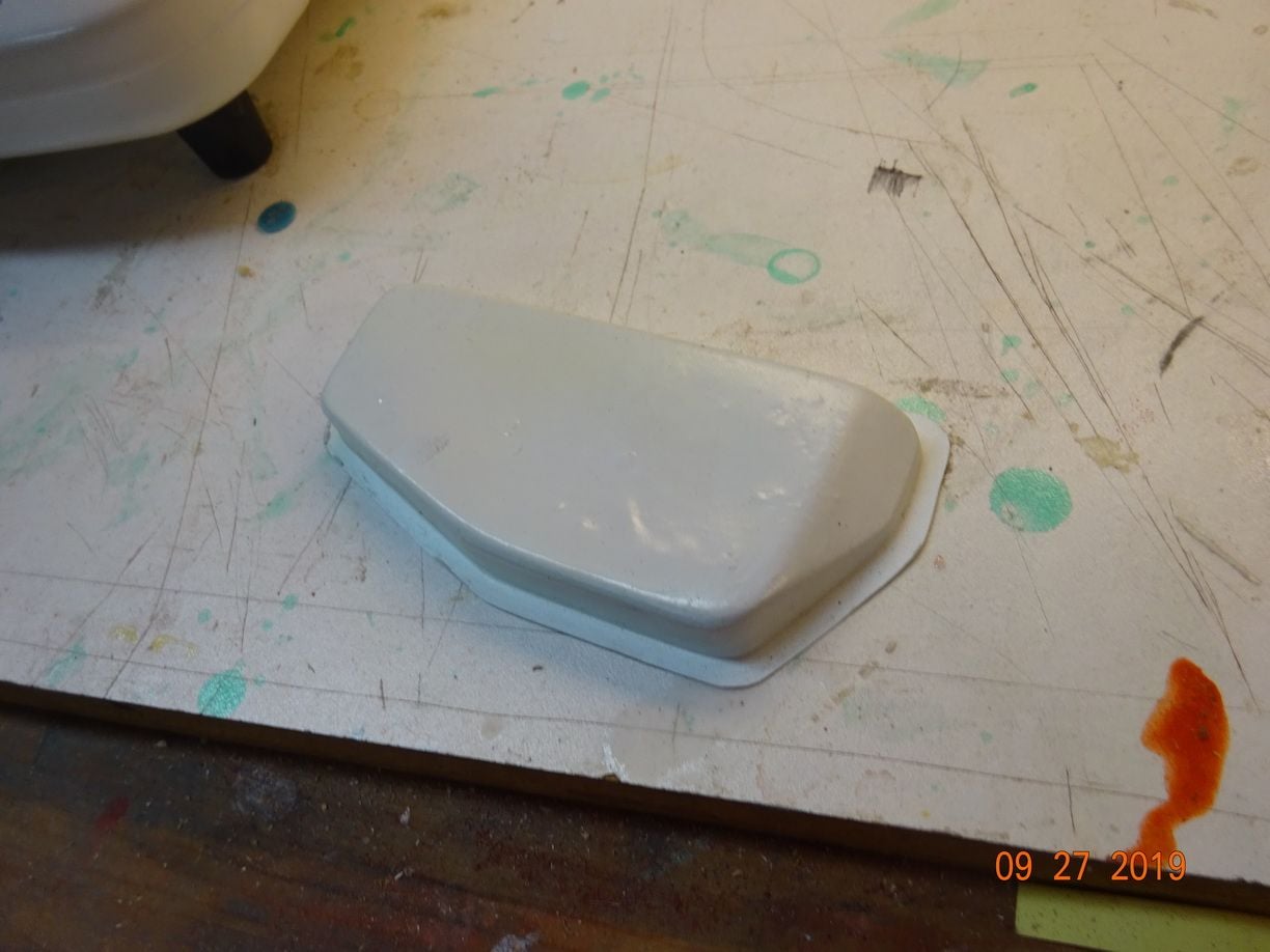
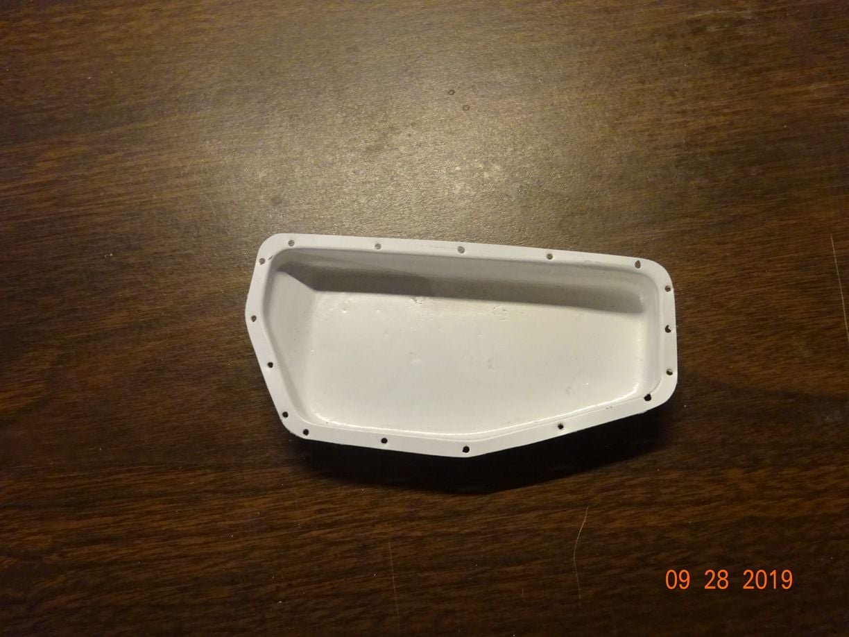
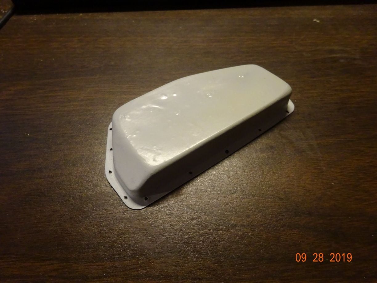
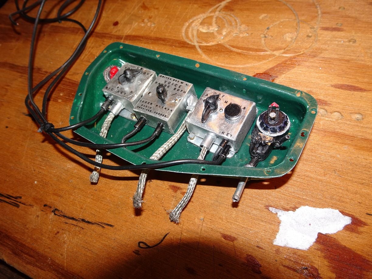
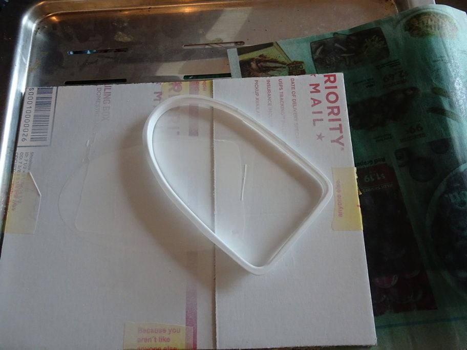
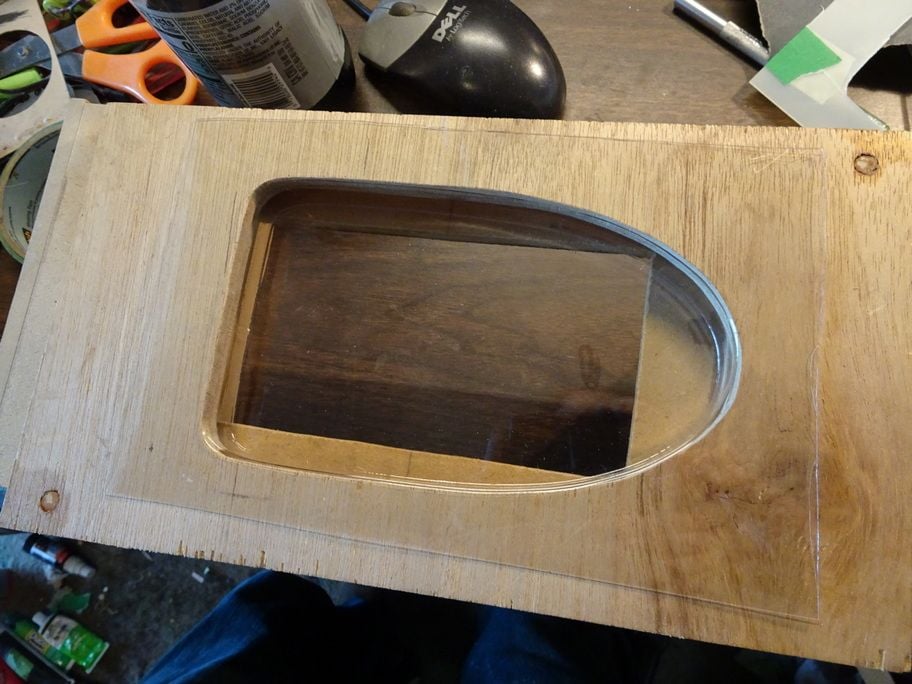
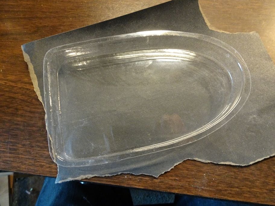
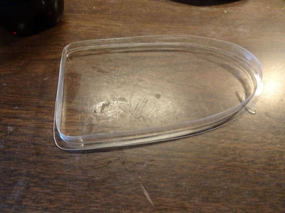
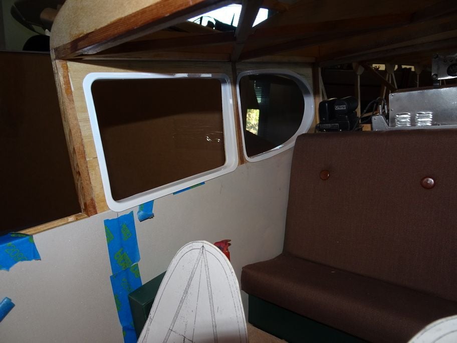
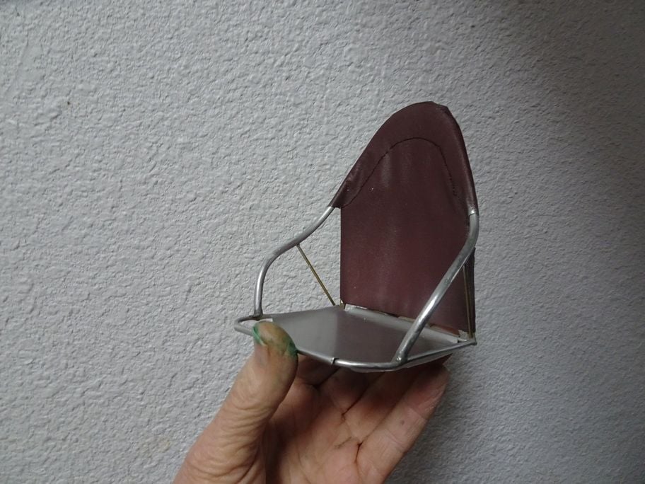
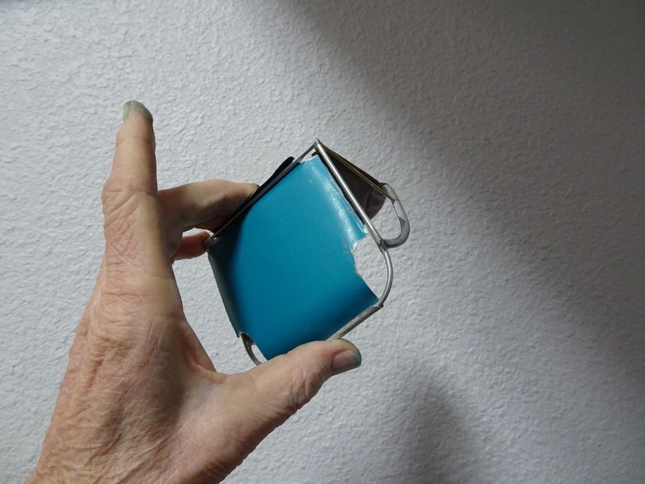
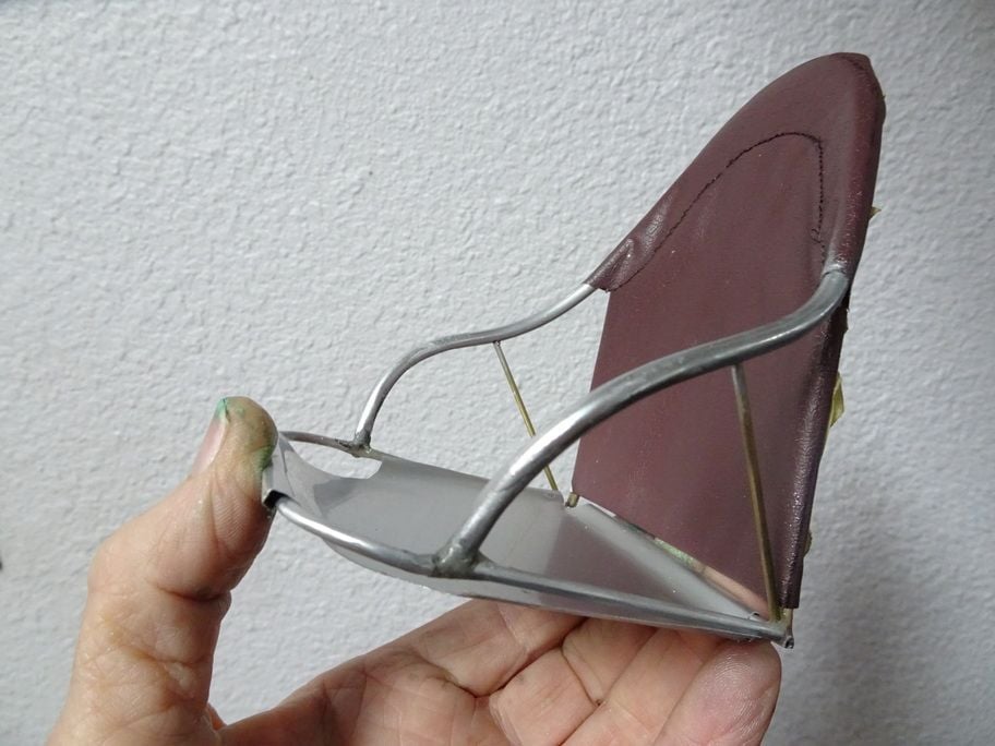
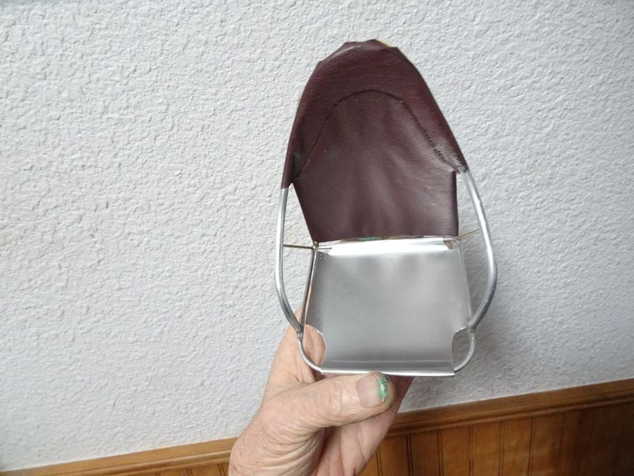
..............Above is a procedure for making some items using stretch forming.......shown is the left front cockpit radio control console .........this process was also used to make the inner window moldings as seen on the door, also the top of the dash just above the instrument panel, the the engine baffles, the mike tray, and the marker light lenses.....

 02-27-2021, 12:18 PM
#1304
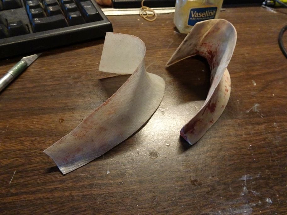
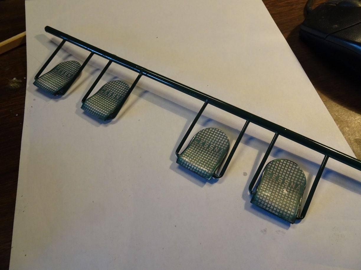
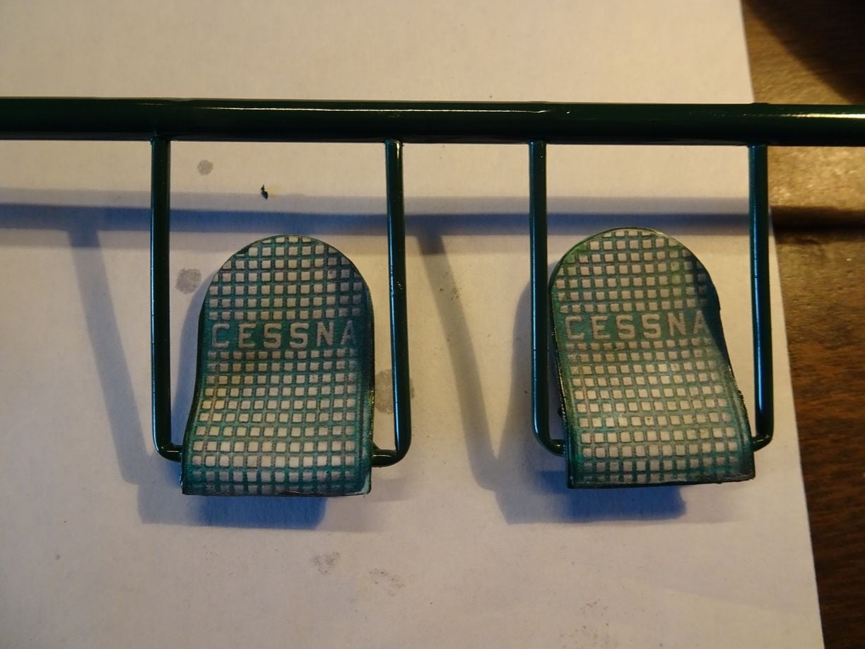
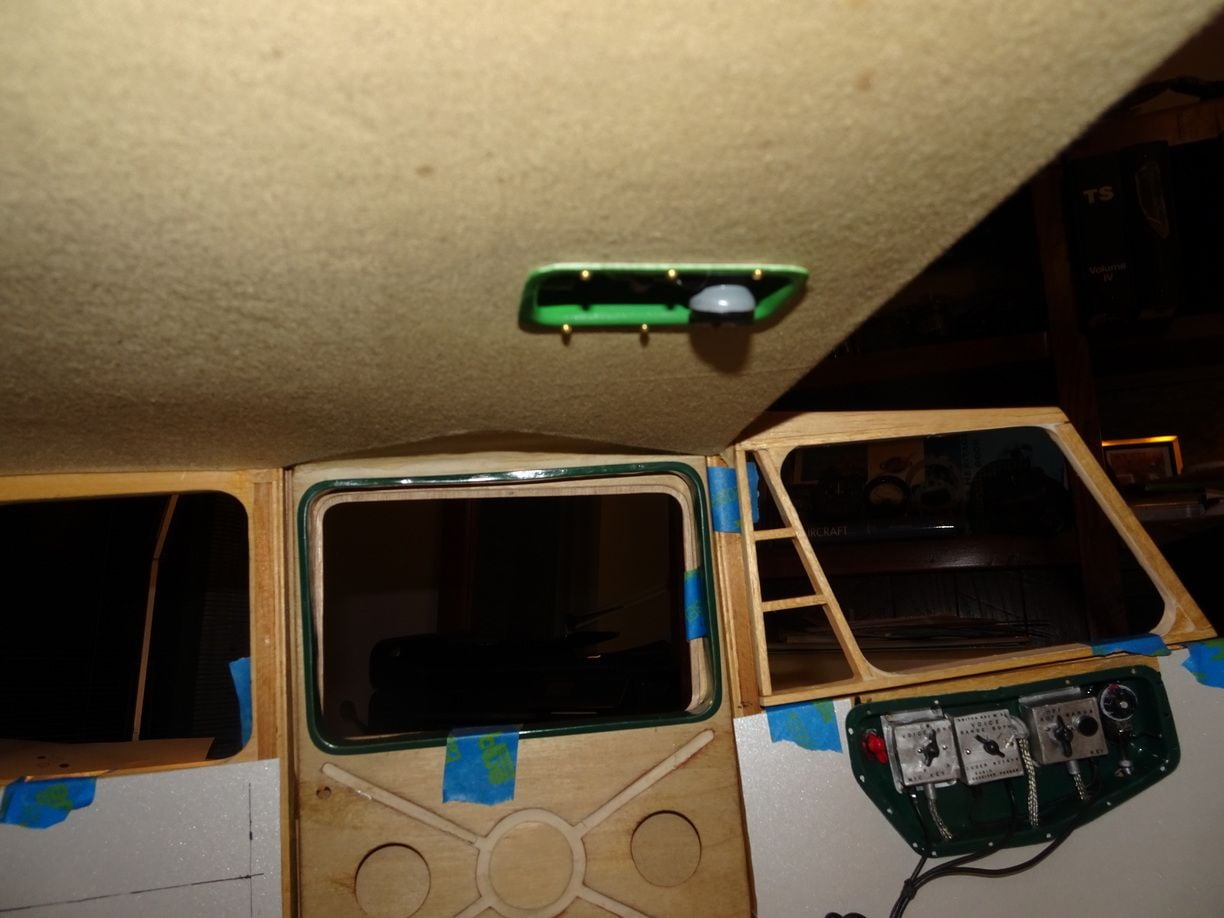
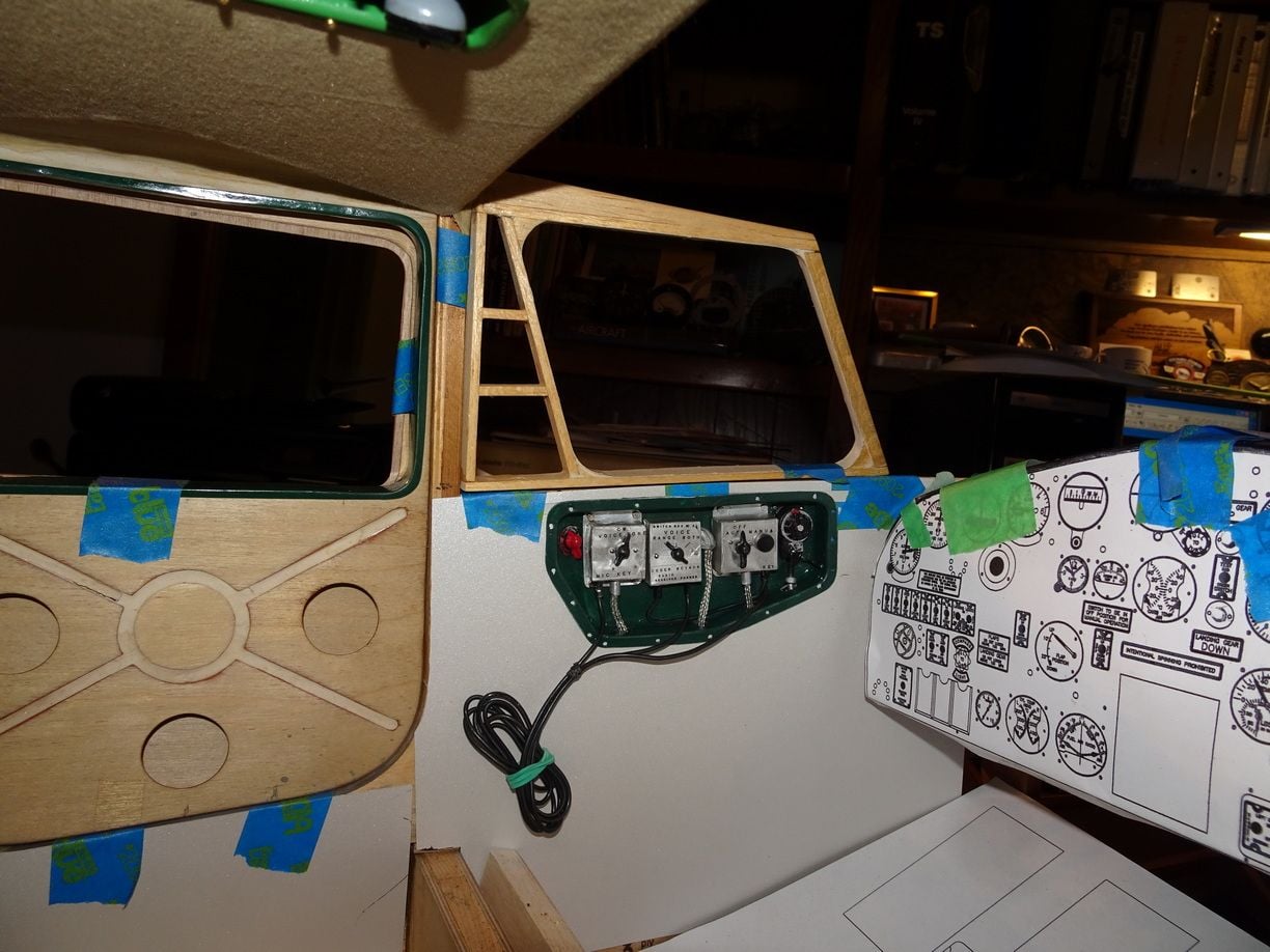
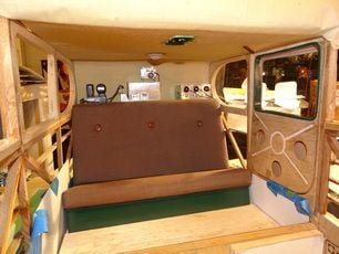
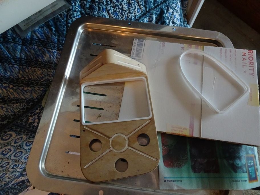
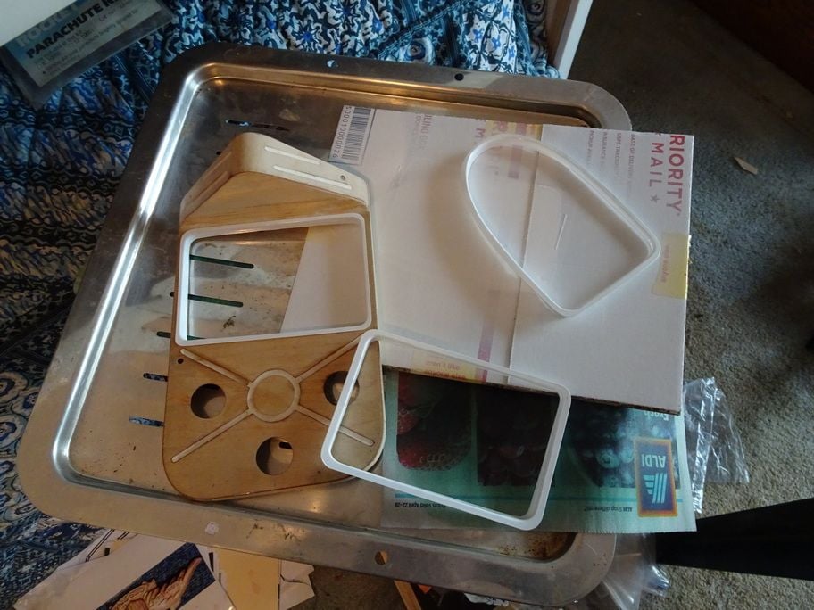
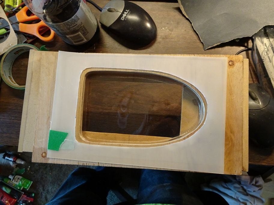
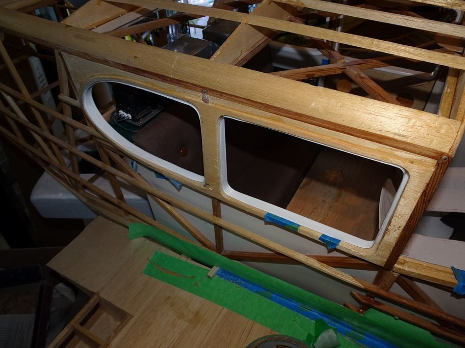
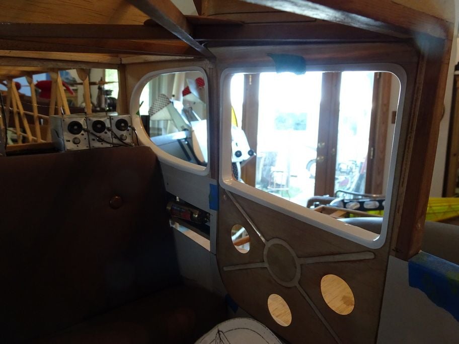
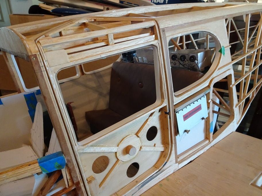
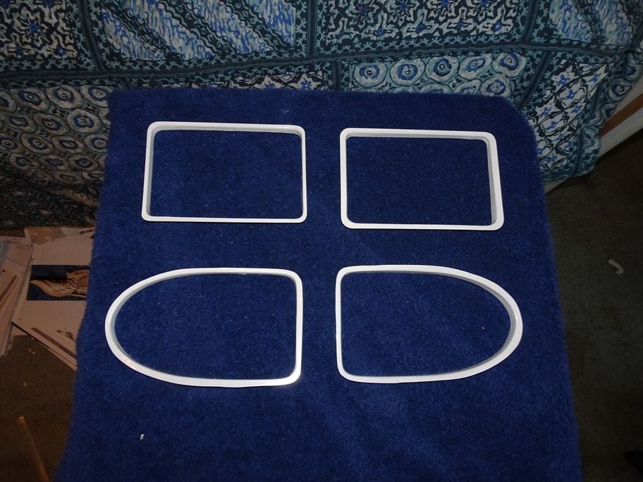
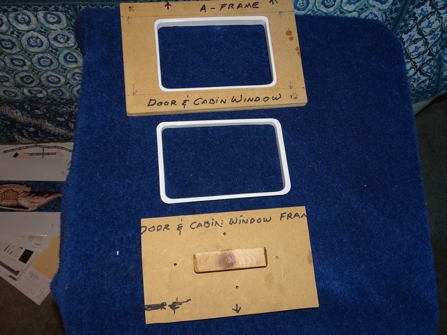
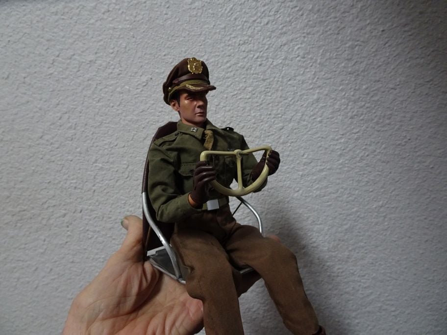
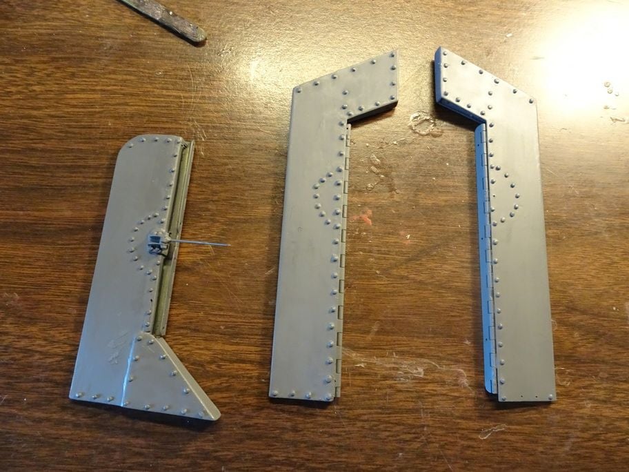
...........Above are the window and door frames using the stretch forming method, this takes a little tine design the forms on Auto-Cad because they have to be correct, then the assembly.........most of the time making them is building......once made the frames were formed in about an hour..........so if any one needs a set of window frames for a 1/5 scale Bobcat let me know, it really looks great especially when the pane is installed.
02-27-2021, 05:49 PM
#1306

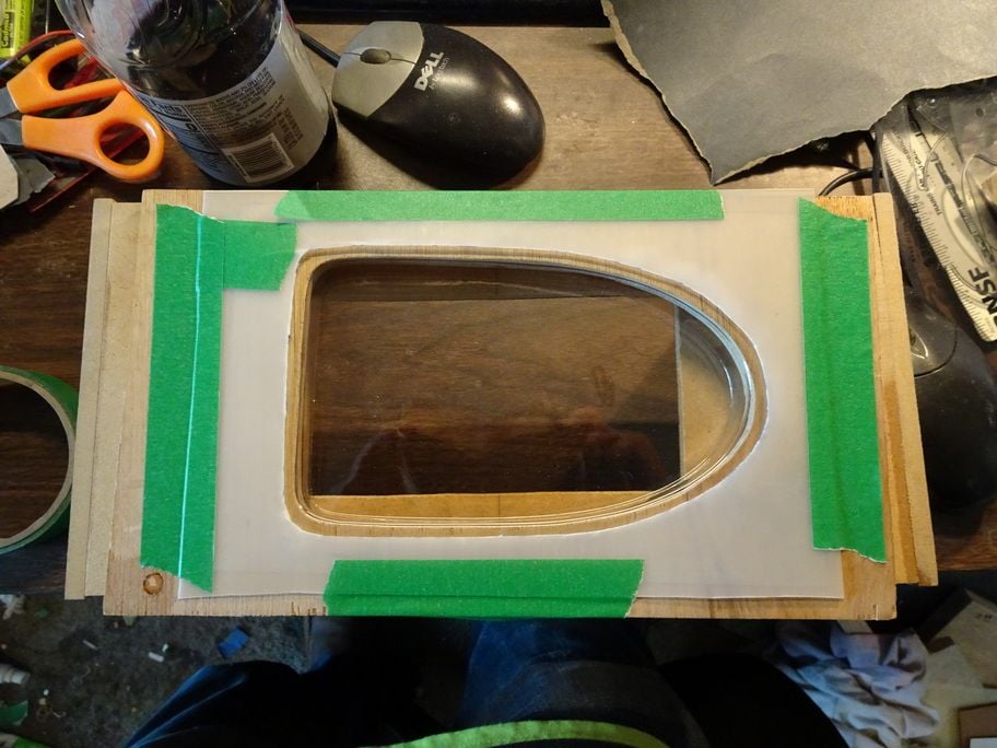
...........Above are the window and door frames using the stretch forming method, this takes a little tine design the forms on Auto-Cad because they have to be correct, then the assembly.........most of the time making them is building......once made the frames were formed in about an hour..........so if any one needs a set of window frames for a 1/5 scale Bobcat let me know, it really looks great especially when the pane is installed.
02-27-2021, 06:19 PM
#1308
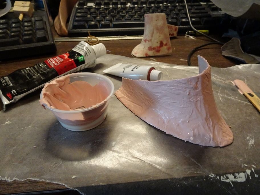
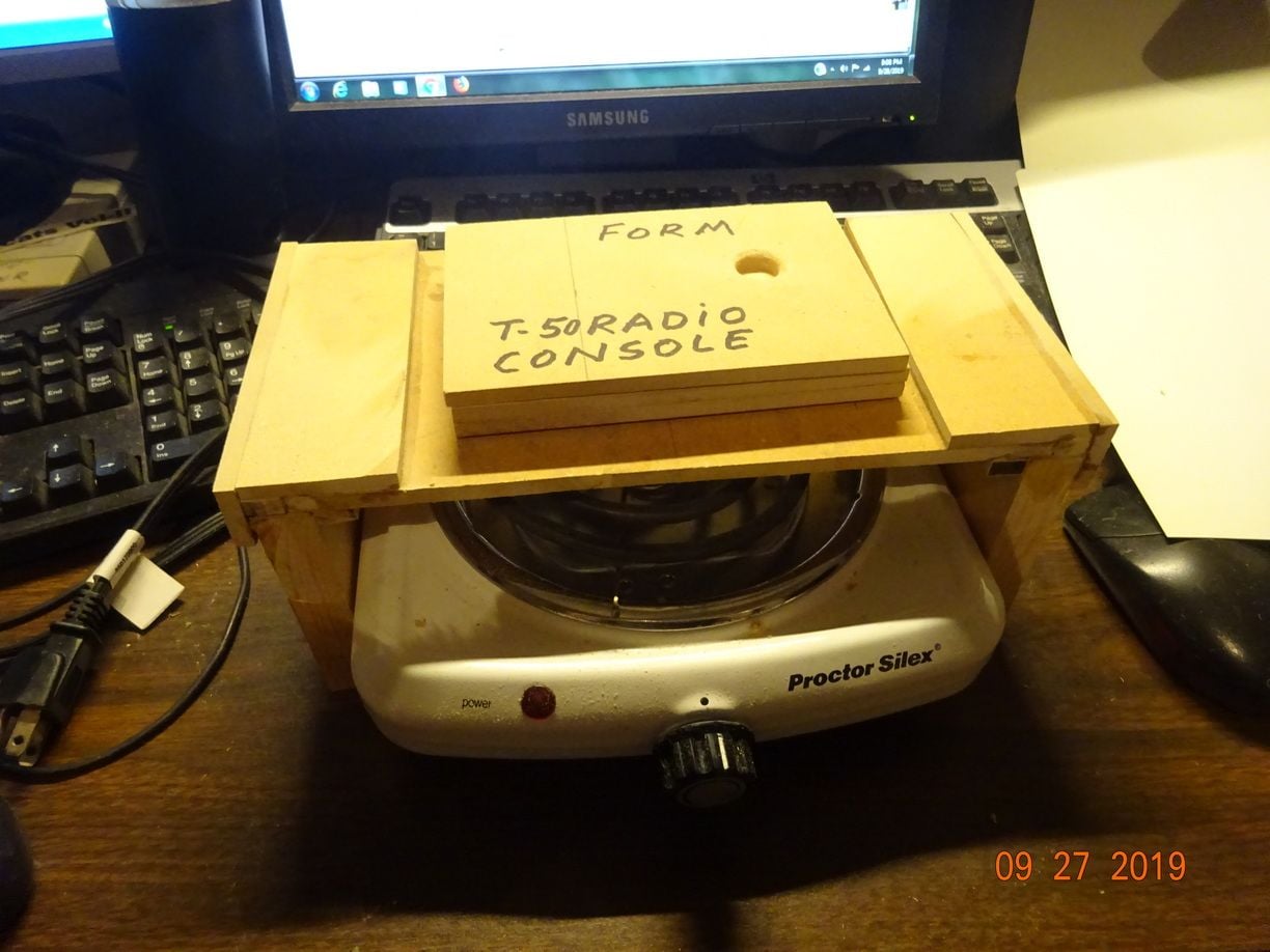
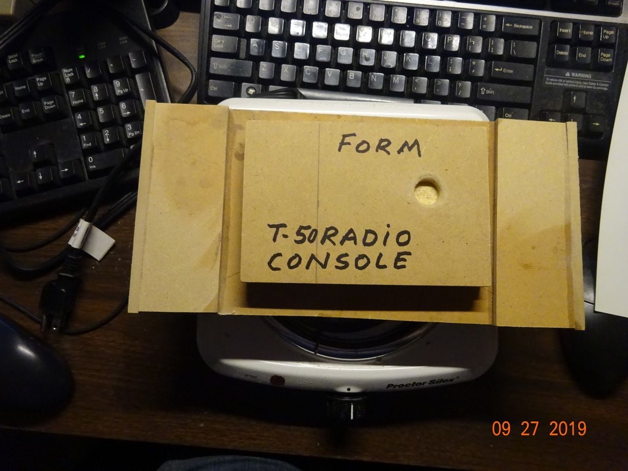
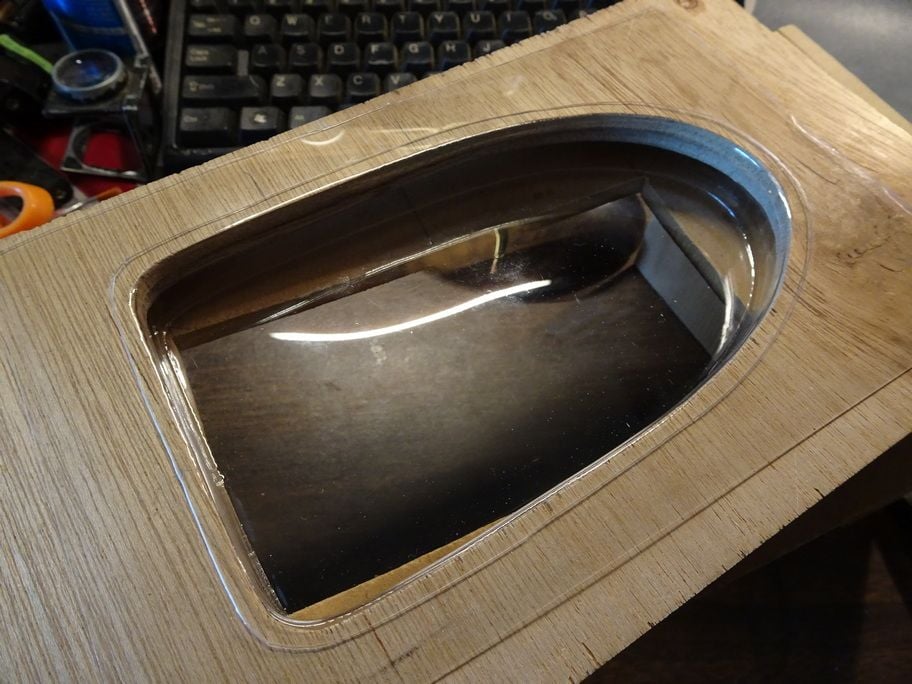
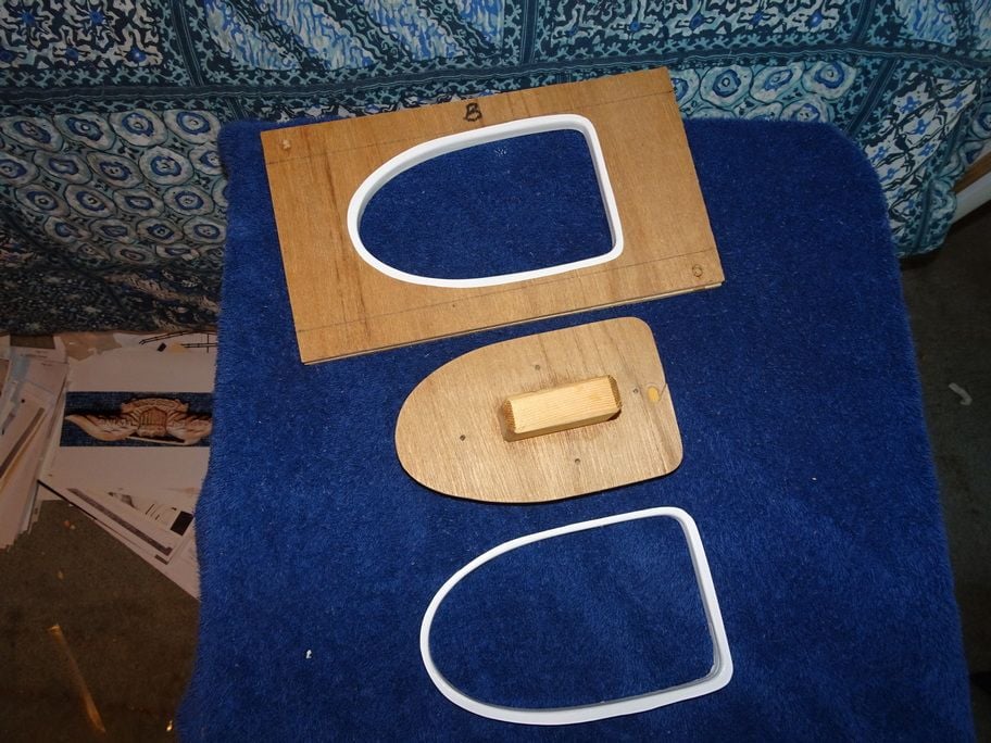
........Yes, it doe's involve heat..........I used a hot plate for the heat source so I could control the temperature, a critical part of the process.
not enough heat and and you wont be able to form the part, too much heat and you will end up pushing the form right thru the poly plastic or the part will end up distorted, so it takes a few failures before you learn what temp to use for the type of plastic and the thickness that you want......
not enough heat and and you wont be able to form the part, too much heat and you will end up pushing the form right thru the poly plastic or the part will end up distorted, so it takes a few failures before you learn what temp to use for the type of plastic and the thickness that you want......
 03-01-2021, 04:48 PM
#1310
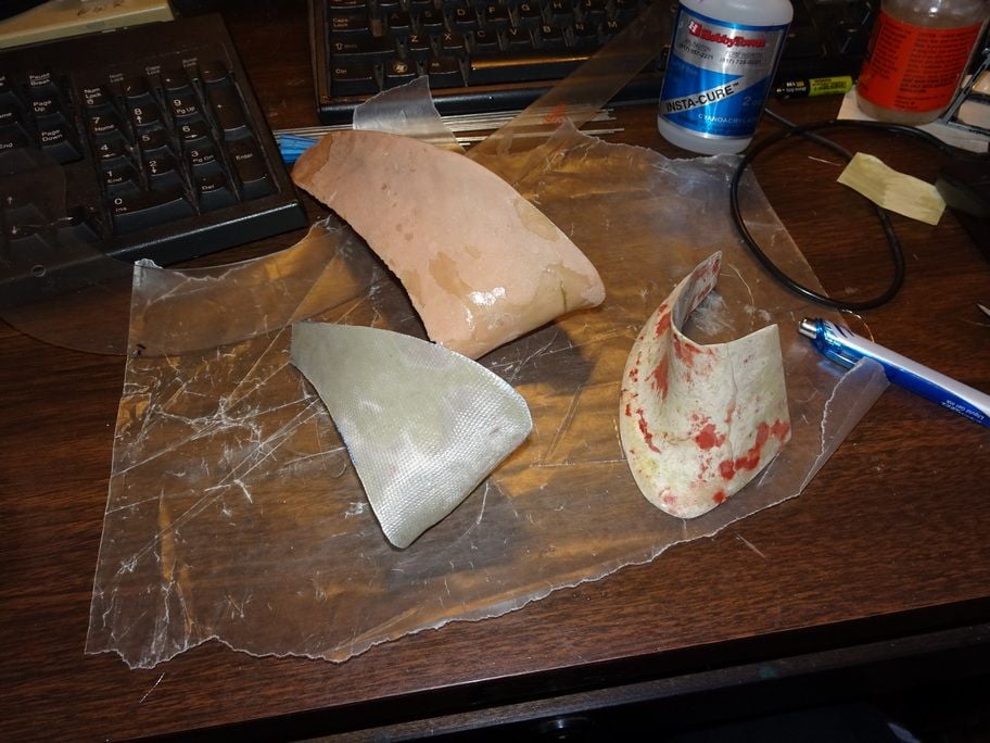
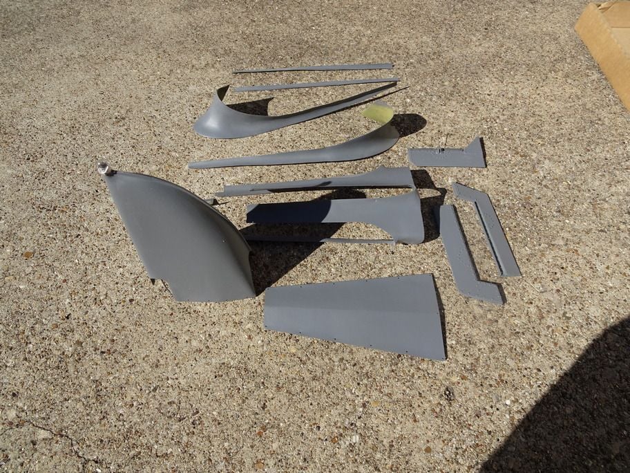
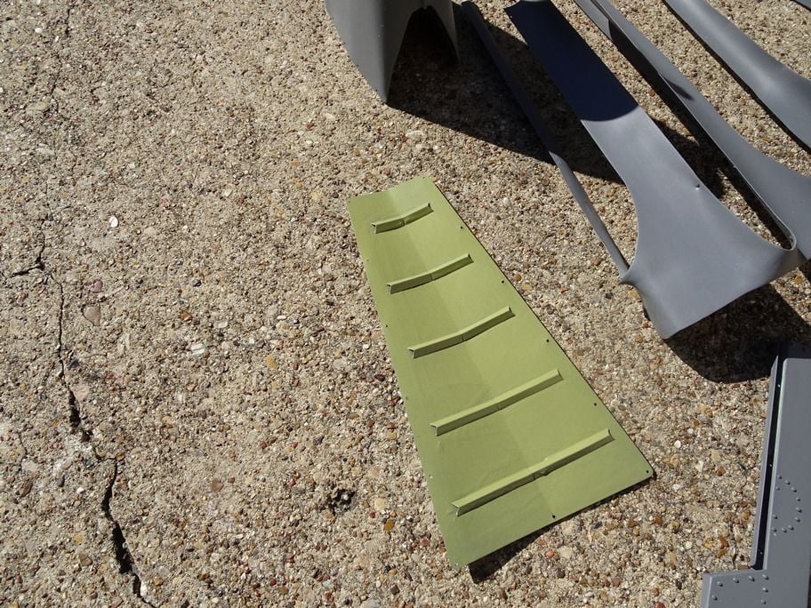
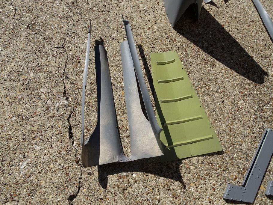
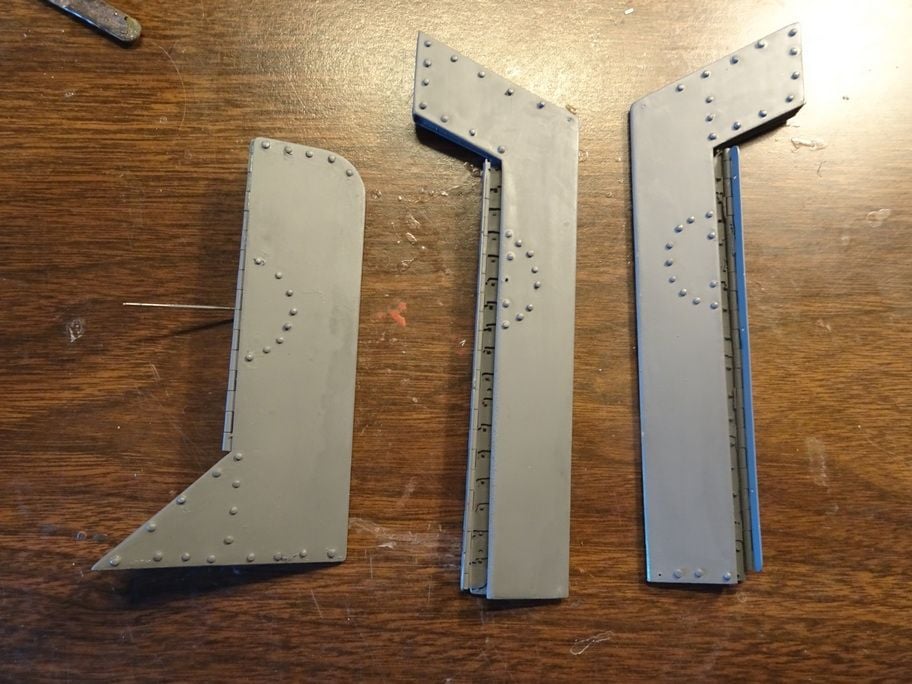
.............Rudder and elevator trim tabs, Stabilizer and fin farings, elevator and rudder controls inspection and access panel, wing fairings and tail stinger with marker light........


 03-02-2021, 11:04 AM
#1313
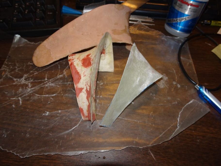
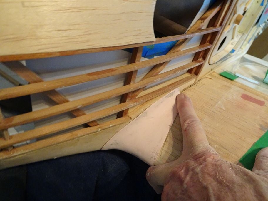
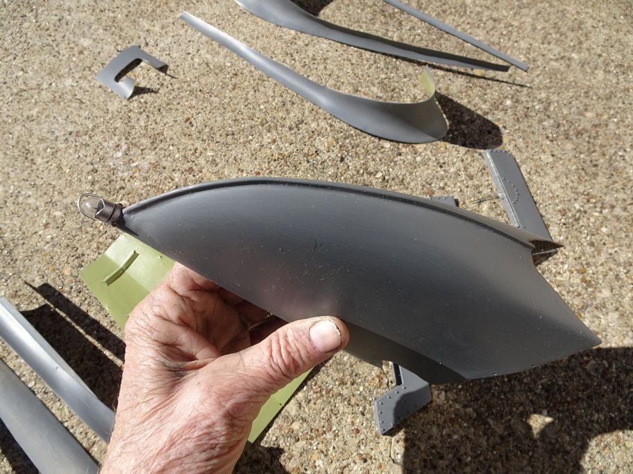
............Yes, the wing fairings are made of 1/2 oz fiberglass inpregnated with thin CA instead of resin.......the stab fairings are made of bond paper coated on both sides with Thin CA to make it stiff......
03-02-2021, 12:10 PM
#1315
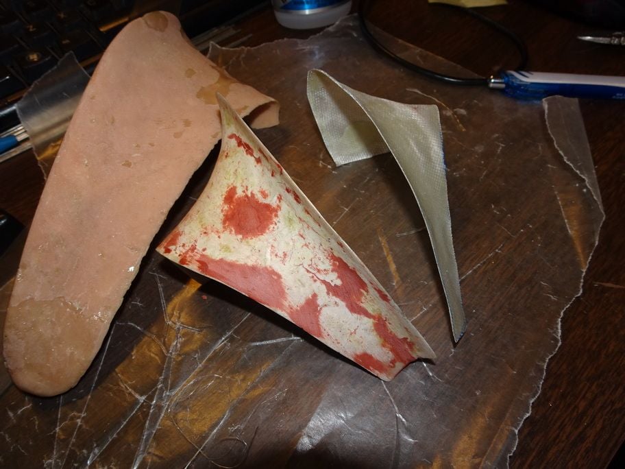
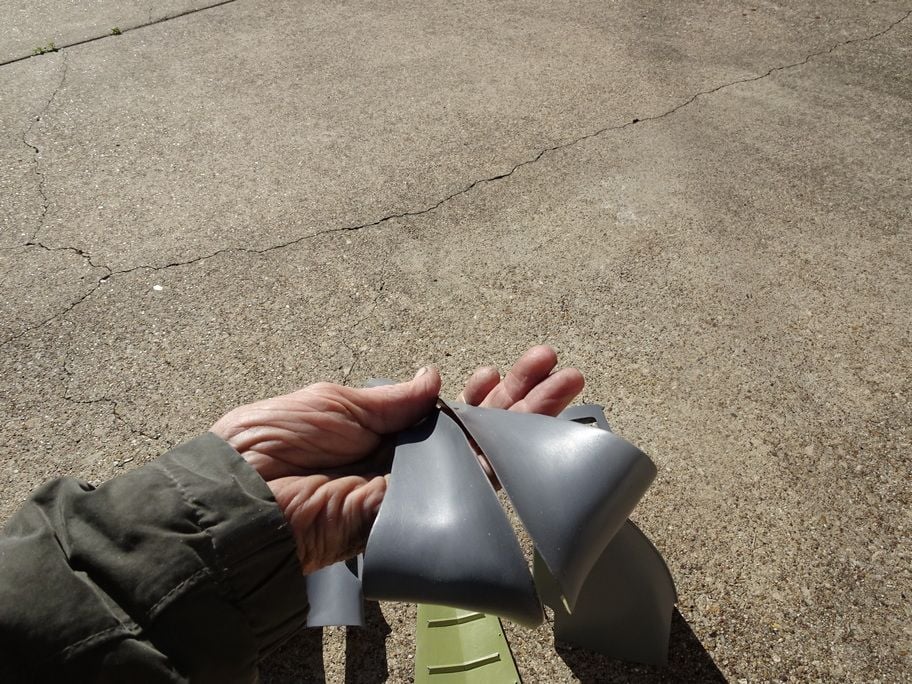
..........Exactly, but you do need to use a release agent due to the fact that CA will stick to just about any thing, I used a mold release from Alumilite, but had good results with mineral spirits with a table spoon of petroleum jelly.
The horizontal stab and vertical stab fairing was made of stiff bond paper formed and hardened by coating both sides also with thin CA.......all of the parts shown except the tail cone are of paper or 1/2 oz fiberglass.
The horizontal stab and vertical stab fairing was made of stiff bond paper formed and hardened by coating both sides also with thin CA.......all of the parts shown except the tail cone are of paper or 1/2 oz fiberglass.
03-02-2021, 01:57 PM
#1316
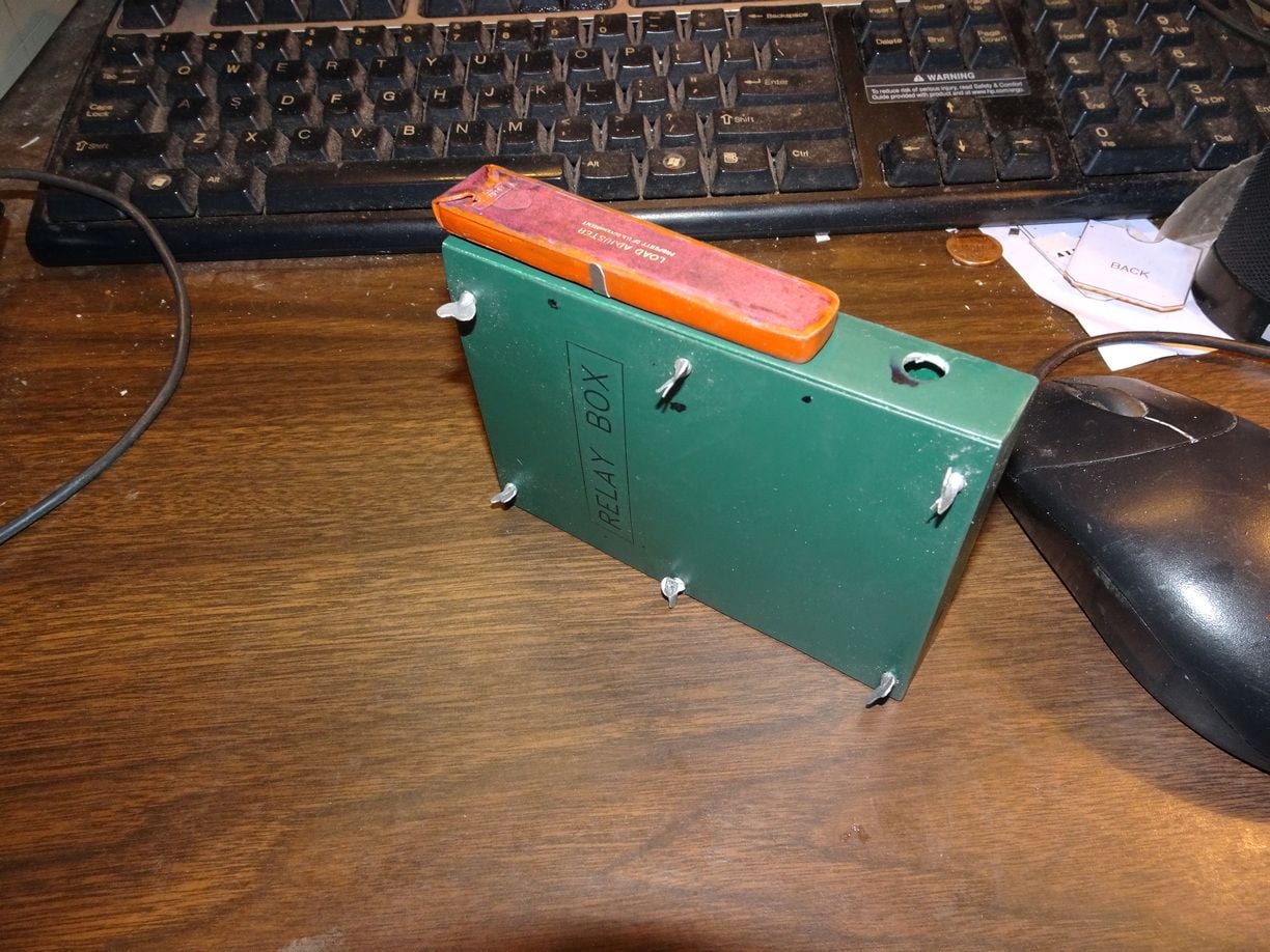
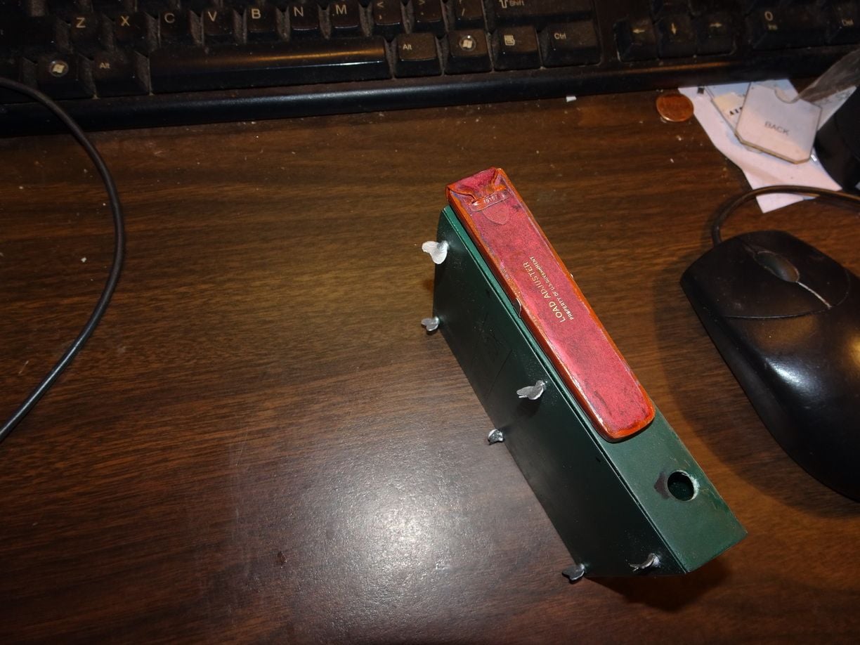
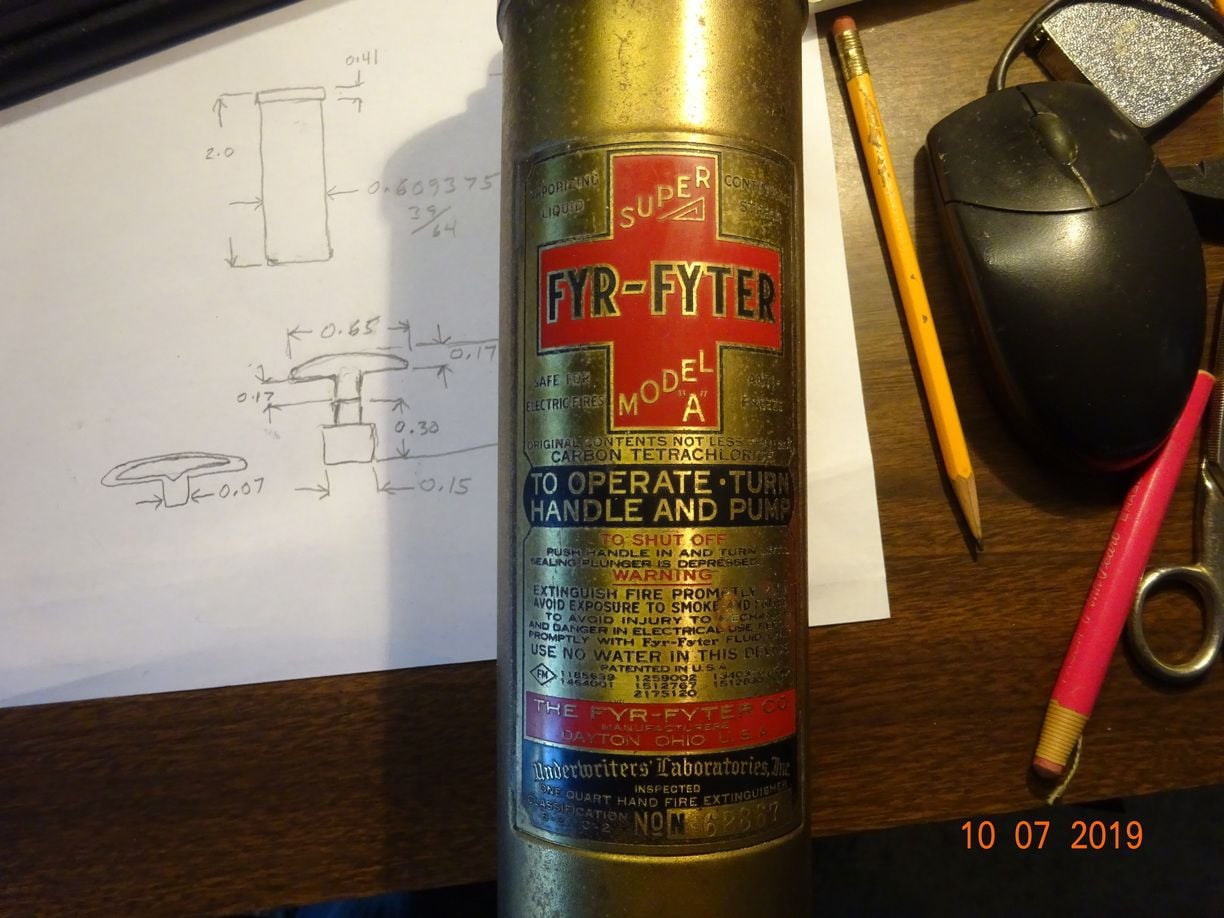
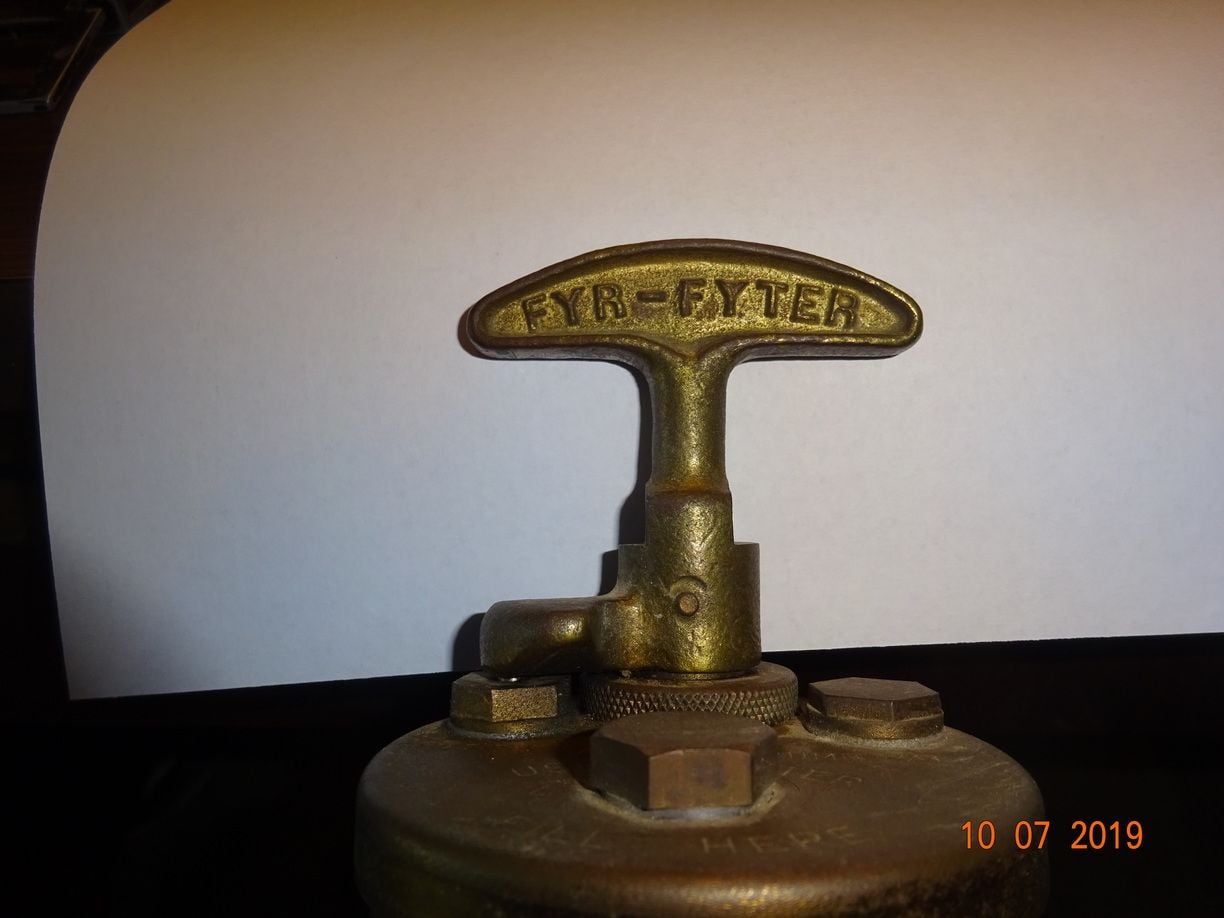
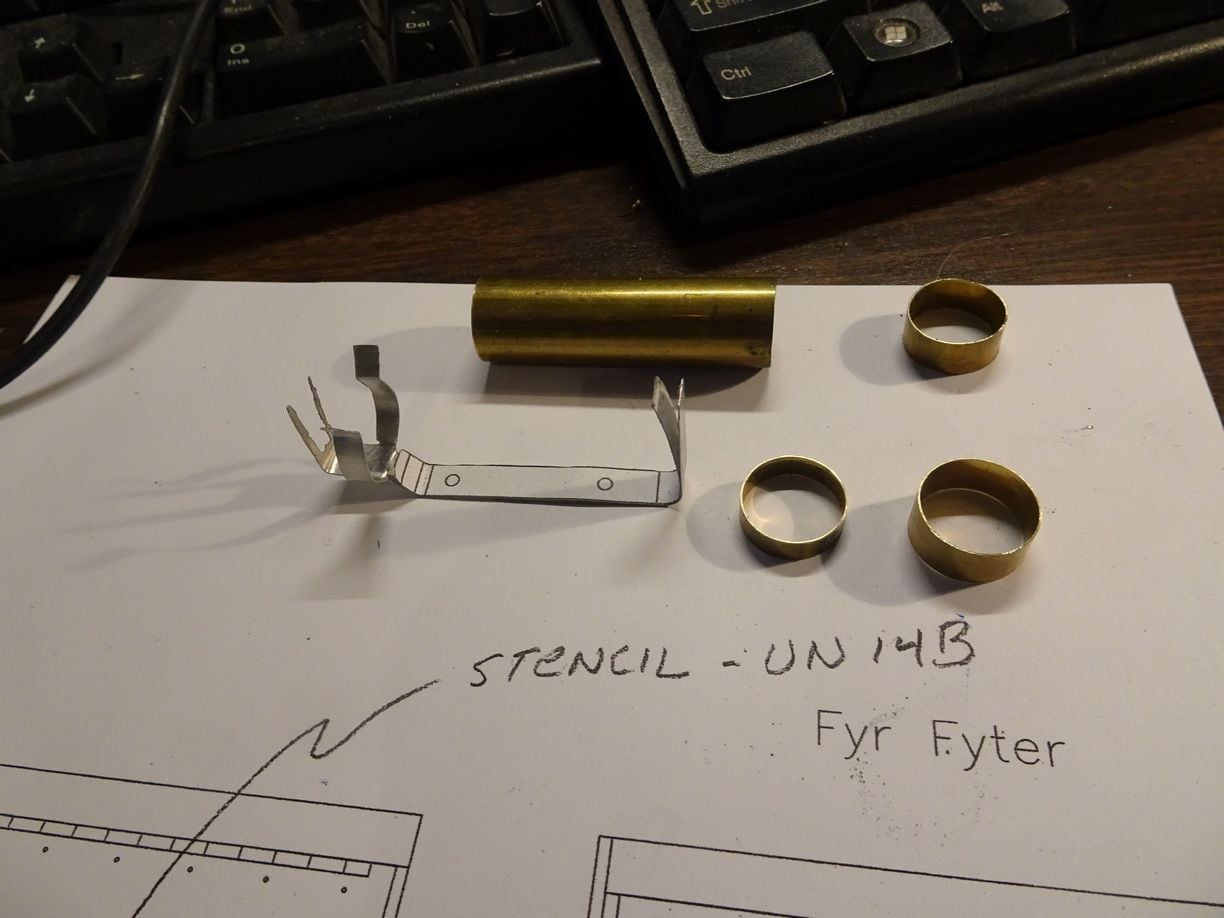
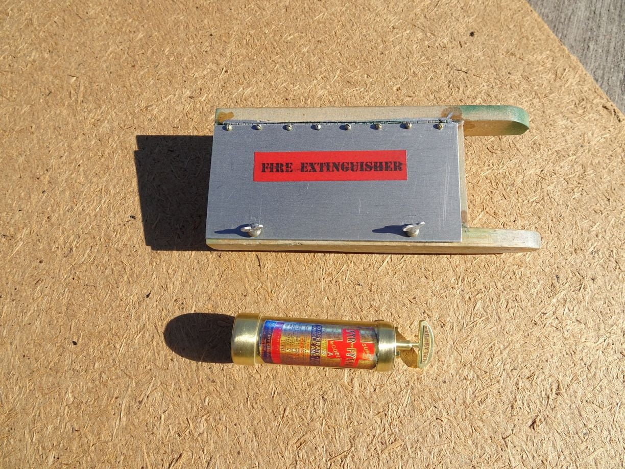
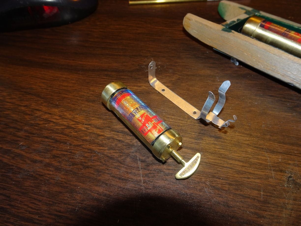
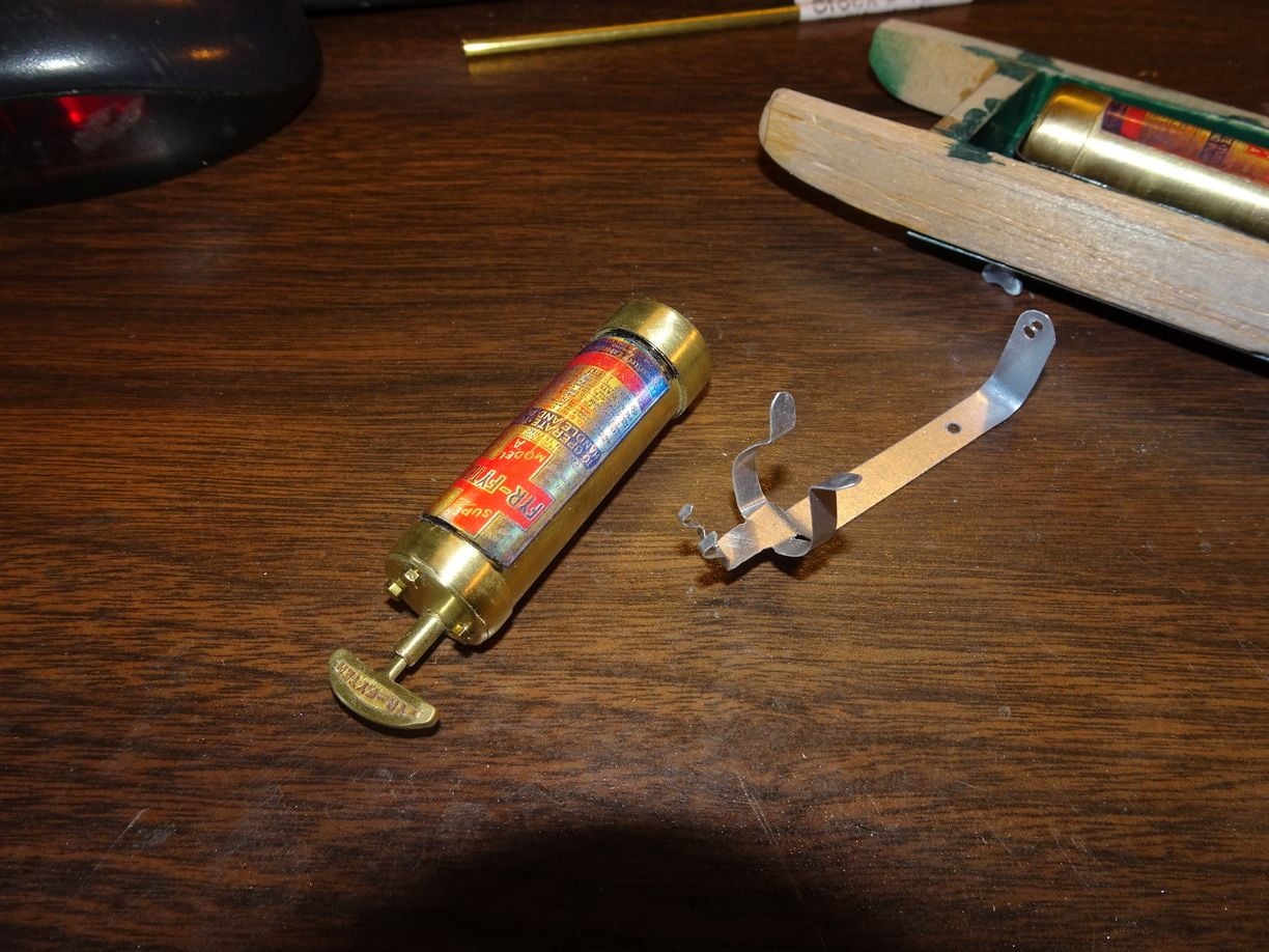
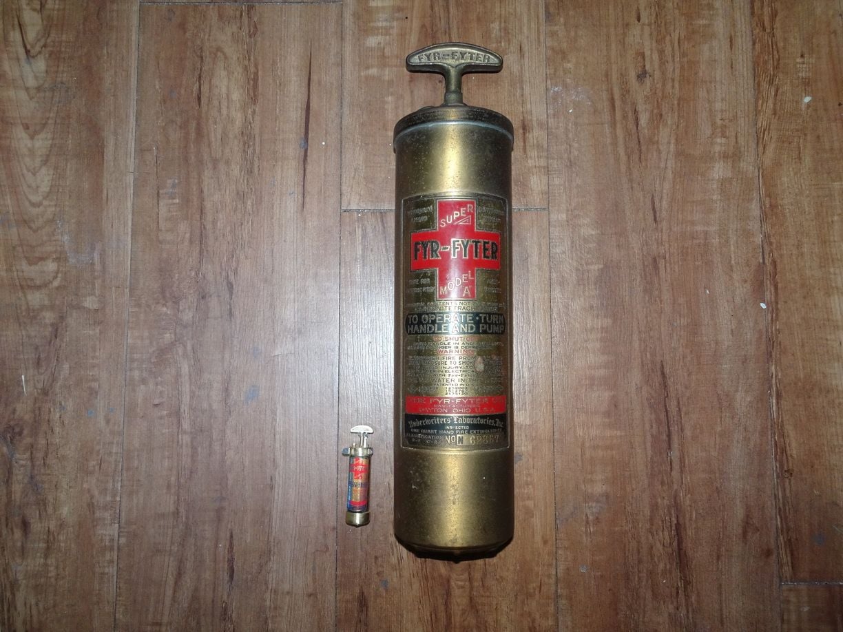
..........How about adding a fire extinguisher?...........the UC-78 had two of them, one up front on the floor in the cockpit, and the other in a compartment on the port side with access from inside and outside with a door with a red field with the words "Fire Extinguisher" ......
03-02-2021, 04:43 PM
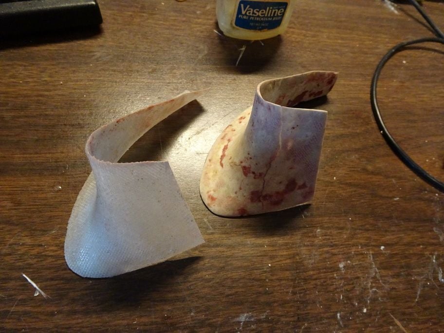
#1317
..........Tony, I used a male mold only from paper mache.......mixed with water it is much like working with clay.......when dry it can be sanded and filled.......once a form is made for both sides I then apply the cloth right on top and start at one end with the CA and work my way back to the end......unlike resin, it sets up as you go, so no need to wait for setup.......once removed from the form it's ready to fill with bondo......