


Spektrum Telemetry module and iPhone App.
 03-08-2012, 05:14 AM

Since I have almost Zero confidence on getting the Electronic Brushless sensor to work, (Just too many variables, EMI, Pole#, speed up slow down issues) it occurs to me that using the dots on the can of the Turnigy Outrunner might be a whole lot easier and more accurate.
Pull-Up-Now, you did some testing as I recall putting the dots on a Drill Press chuck. What do you think of the idea to place the pick ups on the outside of the spinning Outrunner can? The G-32 has a nice black finish on the outside, and I can see no problem in mounting a bracket for the sensor. (at 6 bucks I already ordered one) What are your suggestions? Should I go with 2 dots and set the poles to "2" or go with 4 dots to get more accuracy? Do you have the STi module and can you test to see if it likes the optical feed?(see above test in #475)
KKKKFL
 03-08-2012, 06:41 AM
Andy
03-08-2012, 06:51 AM
KKKKFL
 03-08-2012, 08:25 AM
KKKKFL
03-08-2012, 02:39 PM
After talking with the Spektrum rep this morning, it was obvious to me that the ESC needs to have the capability to pulse at various rates. The 60 amp Dynam (20 bucks) only has Hard or soft settings, the (80 buck) E-flight 60 amp ESC has programmable settings designated for the poles of the motor 2-4, 6-12, 12 poles, 14 or more poles. I just gave in... the sensor was designed to work with specified poles, These need to be set in the DX8, as well as the STi if there's gonna be any hope of a correct read-out. The default settings on the ESC will NOT work. You must go into program mode for the ESC and select the correct Pole setting. I lost some of the wattage using the E-flight, down to 780 watts, where the Dynam was drawing 840 Watts. Different props might change this.
After replacing the connectors, and making the changes, I held my breath and fired it up. Results, It starts reading over 4000 RPM, reads accurately at least up to 8880 RPM (verified with optical Tach) where it topped out with the current prop. Slowly backing down, it will give some false reads, but settle in and track. It does not read below 3000 RPM and that's about as good as its going to do. Actual RPM readings on an electric plane is of limited usefulness, and I can live with the results. Not their finest sensor, but it does move the needle correctly some of the time. I am more pleased with the STi 3 axis output screen and the fact that the DO DISPLAY VARIOMETER readings!! This might be an interim output until the actual Barometric sensor comes to this country, but for you glider guys, it is there. I don't know if the reading will emit a rising tone for lift, and decending one for sink. I'll know more this weekend.
Thanks to Andy & Bruce... keep up the good work.
KKKKFL
03-10-2012, 06:18 AM
<meta name="Title"><meta name="Keywords"><meta content="text/html; charset=utf-8" http-equiv="Content-Type"><meta content="Word.Document" name="ProgId"><meta content="Microsoft Word 2008" name="Generator"><meta content="Microsoft Word 2008" name="Originator"><link href="file://localhost/Users/francolubinsky/Library/Caches/TemporaryItems/msoclip/0clip_filelist.xml" rel="File-List" /><xml> <o
 fficedocumentsettings> <o:allowpng></o:allowpng> </officedocumentsettings></xml><xml> <w:worddocument> <w:zoom>0</w:zoom> <w:trackmoves>false</w:trackmoves> <w:trackformatting></w:trackformatting> <w
 unctuationkerning></wunctuationkerning> <w:drawinggridhorizontalspacing>18 pt</w:drawinggridhorizontalspacing> <w:drawinggridverticalspacing>18 pt</w:drawinggridverticalspacing> <w:displayhorizontaldrawinggridevery>0</w:displayhorizontaldrawinggridevery> <w:displayverticaldrawinggridevery>0</w:displayverticaldrawinggridevery> <w:validateagainstschemas></w:validateagainstschemas> <w:saveifxmlinvalid>false</w:saveifxmlinvalid> <w:ignoremixedcontent>false</w:ignoremixedcontent> <w:alwaysshowplaceholdertext>false</w:alwaysshowplaceholdertext> <w:compatibility> <w:breakwrappedtables></w:breakwrappedtables> <w:dontgrowautofit></w:dontgrowautofit> <w:dontautofitconstrainedtables></w:dontautofitconstrainedtables> <w:dontvertalignintxbx></w:dontvertalignintxbx> </w:compatibility> </w:worddocument></xml><xml> <w:latentstyles latentstylecount="276" deflockedstate="false"> </w:latentstyles></xml><style type="text/css"></style><style type="text/css"> Style Definitions */table.MsoNormalTable {mso-style-name:"Table Normal"; mso-tstyle-rowband-size:0; mso-tstyle-colband-size:0; mso-style-noshow:yes; mso-style-parent:""; mso-padding-alt:0in 5.4pt 0in 5.4pt; mso-para-margin-top:0in; mso-para-margin-right:0in; mso-para-margin-bottom:10.0pt; mso-para-margin-left:0in; line-height:115%; mso-pagination:widow-orphan; font-size:11.0pt; font-family:"Times New Roman"; mso-ascii-font-family:Calibri; mso-ascii-theme-font:minor-latin; mso-hansi-font-family:Calibri; mso-hansi-theme-font:minor-latin;}</style><xml> <o:shapedefaults spidmax="1026" v:ext="edit"></o:shapedefaults></xml><xml> <o:shapelayout v:ext="edit"> <o:idmap data="1" v:ext="edit"></o:idmap> </o:shapelayout></xml>
Programming Menu 3 – Timing<o></o>
The defaultsetting is 15 degrees. As a general rule, lower pole count motors use lowertiming and higher pole count motors use higher timing. Please refer to yourmotor instructions and specifications for an indication of the number of poles.(Default is 15 degrees)<o></o>
LowTimingAdvance<o></o>
TimingDegrees – 5 & 10<o></o>
MotorPoles – 2 to 4 <o></o>
ExpectedPerformance – Good balance of power and efficiency<o></o>
MotorPoles – 6 or more<o></o>
ExpectedPerformance – Best efficiency and run time (lowest power)<o></o>
StandardTimingAdvance<o></o>
TimingDegrees – 15 & 20<o></o>
MotorPoles – 6 to 12<o></o>
ExpectedPerformance – Good balance of power and efficiency<o></o>
MotorPoles – 14 or more<o></o>
ExpectedPerformance – Best efficiency and run time (lowest power)<o></o>
HighTimingAdvance<o></o>
TimingDegrees – 25<o></o>
MotorPoles – 12 <o></o>
ExpectedPerformance – Highest power, less efficiency<o></o>
MotorPoles – 14 or more<o></o>
ExpectedPerformance – Good balance of power and efficiency<o></o>
<o></o>
<o></o>
1.Move the stick to center (between 1.4 and 1.6ms)for 5 seconds, and the controller will beep 3 times, indicating you are now inMenu 3. <o></o>
<o></o>
2.Move the throttle stick to full throttle(>1.7ms) position to make changes to the Timing programming. <o></o>
<o></o>
a.To select 5 Degrees, (2 to 4 Poles*) – You willhear 1 short beep. Move the throttle stick to center (between 1.4 and 1.6ms).The controller will beep 2 times, indicating you have set the program selectionor leave in full throttle for 5 secondsto advance to the next selection. <o></o>
<o></o>
b.To select 10 Degrees(4 to 6 Poles**) – You willhear 2 short beeps. Move the throttle stick to center (between 1.4 and 1.6ms).The controller will beep 2 times, indicating you have set the program selectionor leave in full throttle for 5 seconds to advance to the next selection. <o></o>
<o></o>
<o></o>
c.To select 15 Degrees (6-12 Poles**) – You will hear3 short beeps. Move the throttle stick to center (between 1.4 and 1.6ms). Thecontroller will beep 2 times, indicating you have set the program selection orleave in full throttle for 5 seconds to advance to the next selection. <o></o>
<o></o>
d.To select 20 Degrees (12-14 Poles**) – You willhear 4 short beeps. Move the throttle stick to center (between 1.4 and 1.6ms).The controller will beep 2 times, indicating you have set the program selectionor leave in full throttle for 5 seconds to advance to the next selection. <o></o>
<o></o>
<o></o>
e.Toselect 25 Degrees(14-16 Poles**) – You will hear 5 short beeps<o></o>
Movethe throttle stick to center (between 1.4 and 1.6ms). The controller will beep2 times, indicating you have set the program selection or leave in fullthrottle for 5 seconds to advance to the first selection again. <o></o>
**Thereare 5 settings, for degrees, although the text shows only 3 options, the poleto degree text has been inserted by me and is not from E-flight.<o></o>
<o></o>
<o></o>
<o>next menu....
</o>
Programming Menu 4 – Throttle Input Range (PWM) ...etc.
Hope this helps others trying to get the Brushless RPM sensor to work.
KKKKFL<o></o>
</meta></meta></meta></meta></meta></meta>
03-11-2012, 02:00 PM
03-11-2012, 02:29 PM
03-12-2012, 01:39 PM
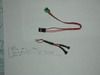
I got it in the mail today.... Absolutely no instructions. The package has 2 small screws for mounting the chip there's the bottom of the printed circuit board, two small bumps on the other side and a length of cable with a connector at the end.
There appears to be a decal sheet with 3 silver bars, and 3 black ones, as well as 3 silver dots and 3 black ones.
What I want to do is attach something to the black can of the Turnigy motor... can I just stick the two silver bars on opposing sides of the motor?
What orientation must the two nubs on the card be mounted at? Mounted one way both sensors would see the strip at the same time, turned 90 degrees, one will see the edge first.
I think the original test had stripes on a drill chuck.
What about the connector? I'm sure it needs to be changed. What color goes where?
Thanks
KKKKFl
03-12-2012, 01:48 PM
Thanks
03-13-2012, 02:53 AM
There's a couple video's one has a disk that's all white except for a black stripe, My only question is which way are the nubs positioned. Do both pick ups see the leading edge of the stripe at the same time ie. side by side, or do they see the stripe serially?
I plan on sacrificing a Voltage pickup lead to get the connector, and hopefully I can figure out what color goes where. Then I'm gonna put yellowish masking tape around the can of the G-32 Turnigy motor, and just place a black strip made with a permanent marker for starters. If the readings need more accuracy, I'll go to opposing stripes, and 2 poles or 4 poles, My range is under 10,000 RPM, but I'm really shooting for accurate readings from a low of 1400 to mid of 5000 and high of 9000.
KKKKFL
03-13-2012, 09:20 AM

I usually have to stop and think/guess to what you're referring. No exception here. What are "nubs"???? Are they the little twin IR (infra red) sensor/emitters on the ground sensor's circuit board? Black in color? If so, it doesn't matter which way you orient them. The edge of a stripe passes by the two so fast it's beyond the response time of the sensor to care about orientation. I'm not totally sure of this, but I think one is an light emitter, and the other is the collector (or sensor). I'm betting the light is very non-directional and spreads out, making orientation irrelevant.
If you check your private email, you'll see I already sent you, on Jan 15th, a picture of how to wire the ground connector for air use. Guess you didn't read it.
You can use the motor can to rotate the stripe, or mark, for RPM. But you need to have a plain background all the way around. In other words, nothing can be seen by the sensors to mistake for the timing mark.
Don't sacrifice one of the sensors if you can help it. You can get the connectors for Spektrum at http://www.rc-connectors.com/index.p...roducts_id=258
03-13-2012, 09:34 AM
The can of the Turnigy motor is black, so one technique would be to place the yellowish masking tape around leaving a 1/4 inch space. The problem I see with that is it would be a single pole and I don't think that's an option for the STi or the Dx8 in the # Poles window.
This ought to be easy to set up, and has to work better than the Electronic sensor, which goes bonkers when you back down throttle. Eventually, it settles in and gives an accurate reading, but I've never gotten a reading below 3700 RPM and I recall your first Drill Press test showing something like 670 RPM, next you did the High Speed drill, I just don't recall how well it tracked as you backed off the throttle.
I'll post a pic of my set up once I get it working.
KKKKFL
03-13-2012, 09:47 AM

Speaking of "nubs", what is "WRT"??
No need to wrap yellow tape all around the motor. Just put an 1/8" strip of tape on one place. That will work. It doesn't matter if what the sensor sees is light/dark, or dark/light.
If I recall, just set the DX8 and the STI for two poles. Because the leading edge of the line is one pole, and the trailing edge of the line is the second. The logic doesn't trigger on just a signal rise, or just a signal fall. It counts both. If you want, you can go 50/50 if it makes you feel better. But it won't matter, it's still 2 poles. To the sensor, it's kinda like "duhduhduhduhduhduhduhduh" or da-duh-da-duh-da-duh-da-duh". Either way, there are 8 duhs.
03-13-2012, 11:42 AM
So with nubs down... or sensors toward the desk... I have red in the center brown on the bottom and pink on the top
the "Y" I want to use has a micro male with the edge ticks facing down its pink then black then red
going from top edge coming towards my belly...
Just for your appreciation... I'm guessing the pink goes to pink red goes to red and brown goes to black
Is that pretty much the arrangement?
KKKKFL
03-13-2012, 11:55 AM
[link=http://api.viglink.com/api/click?format=go&drKey=1518&loc=http%3A%2F%2Fwww.rcuniverse.com%2Fforum%2Fpm.a sp%3Fm%3D1709244%26FolderID%3D1&v=1&libid=1331668201688&out=http%3A%2F%2Fimages.rcuniverse.com%2Fforum%2Fu pfiles%2F436333%2FSq47214.jpg&ref=http%3A%2F%2Fwww.rcuniverse.com%2Fforum%2Fpm.a sp%3FFolderID%3D1%26groupName%3DSent&title=RC%20Forums%20-%20RC%20Universe%20discussion%20forums%20for%20RC% 20cars%2C%20rc%20trucks%2C%20rc%20airplanes%2C%20r c%20helis%2C%20rc%20boats%2C%20rc%20jets%2C%20rc%2 0electric%20helis%2C%20rc%20electric%20planes%20an d%20more&txt=rpm_rewiri..l_sensor.jpg&jsonp=vglnk_jsonp_13316682466343]Ground sensor hookup for air[/link]
03-13-2012, 11:59 AM
Optical is definitly red center orange top brown bottom
KKKKFL
 03-15-2012, 03:11 AM
KKKKFL
03-15-2012, 05:26 PM
 03-16-2012, 02:42 AM
03-16-2012, 02:42 AM
03-16-2012, 02:42 AM
What is the minimum RPM reading that you can see on the DX8?
My brushless sensor doesn't seem to trigger or send ACURATE data below 3700 rpm. It doesn't even start to read until the speed is over 4000RPM, and then I can gently and slowly back the throttle down, but once it gets to 3650, readings jump to 25450.
I have tried every pole count from 2 to 14 and between 10 and 14 it will read, but never anything less than 3700. Also, what ESC are you using and have you programmed the ESC timing? I am currently using the E-flight 60 amp ESC. I tried at the 5th setting, and now I'm running at the 4th, since the motor made some funny whining sounds at mid throttle when in the highest timing mode.
Thanks
KKKKFL