


AMR Trainer 26 - (my) official build thread
 03-15-2015, 05:18 PM
#351
Senior Member
Thread Starter

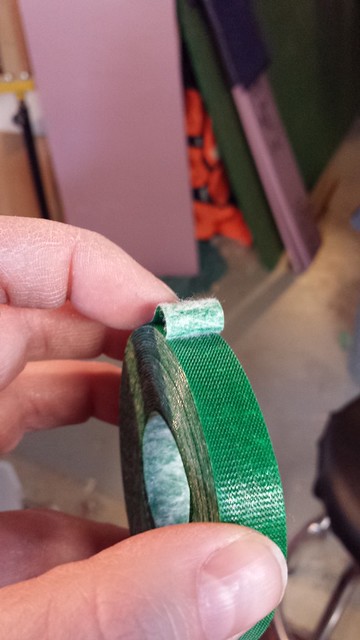
My strapping of choice is Velcro Plant Tie from Lee Valley. Hard to beat at $3.95 for a 30' roll.
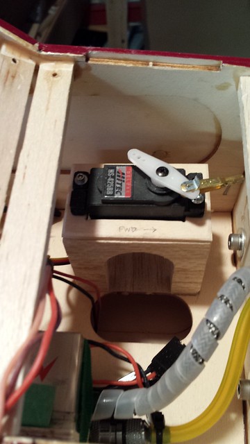
I'm a fan of the Smart Fly ignition cutoff with its fibre optic connection. Here are the transmitter and receiver with foam and platforms.
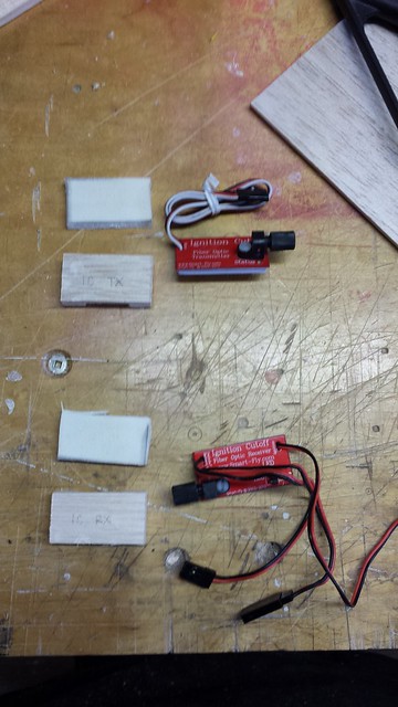
Platforms glued in.
Transmitter and receiver strapped in place.
I'm a fan of the Smart Fly ignition cutoff with its fibre optic connection. Here are the transmitter and receiver with foam and platforms.
Platforms glued in.
Transmitter and receiver strapped in place.
 03-15-2015, 05:25 PM
#352
Senior Member
Thread Starter
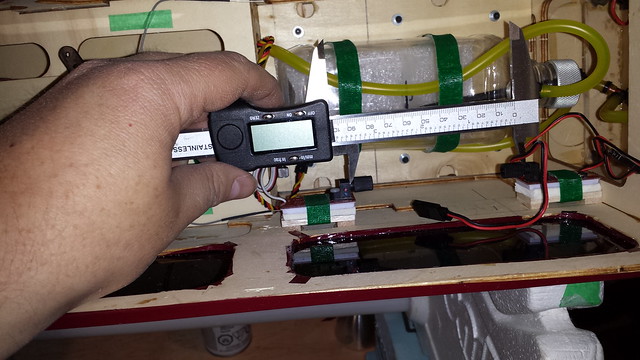
Measuring the length for the fibre optic cable.
I've been thinking for some time about the screws for the fuel dot... they've got sharp points (as screws tend to have) in close proximity to wires and fuel lines.
My first step was to remove each one and round off the edges on a grinder. This large hemostat holds them securely for the job.
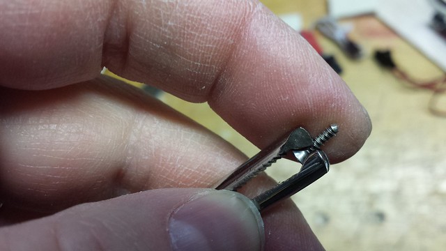
That's a good start. My next step will be to cap them with heat shrink tubing.
I've been thinking for some time about the screws for the fuel dot... they've got sharp points (as screws tend to have) in close proximity to wires and fuel lines.
My first step was to remove each one and round off the edges on a grinder. This large hemostat holds them securely for the job.
That's a good start. My next step will be to cap them with heat shrink tubing.
03-15-2015, 05:31 PM
#353
Senior Member
Thread Starter
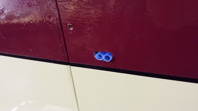
The LED placement was interfering with the throttle servo tray, so out it came. The hole was plugged with a 1/8" length of 1/4" dowel.


Last edited by grosbeak; 03-15-2015 at 05:38 PM.
 03-17-2015, 06:31 AM
#355
Senior Member
Thread Starter
Graphics for the plane (designed in MS Visio, exported to .jpg). Note that the small graphics on the bottom row will not all be used in this build.
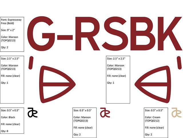
I've made my own in the past using waterslide decals but this time I decided to try a custom vinyl order. I'm going with Callie Graphics - I've heard great things about them and if the quality matches the service and the price I will be mightily pleased.
I've made my own in the past using waterslide decals but this time I decided to try a custom vinyl order. I'm going with Callie Graphics - I've heard great things about them and if the quality matches the service and the price I will be mightily pleased.
03-18-2015, 02:52 AM
#356
Senior Member
Thread Starter
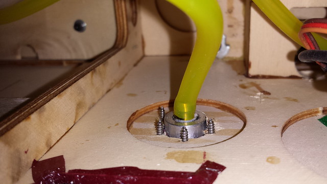
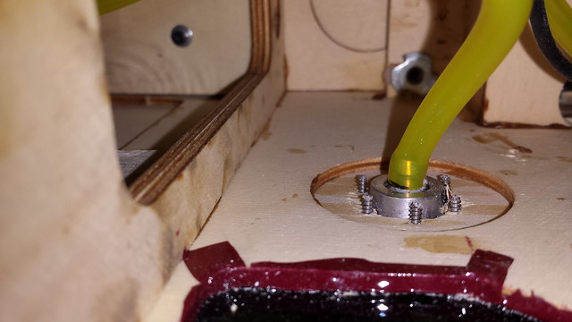
Had a few minutes in the shop last night. The first thing I did was install the Gold'n'Rod outer tube through the firewall. This marks my first use of epoxy in this build.
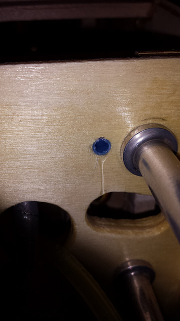
I noticed the drool after I took the photo and yes, I did clean it up.
View from the inside (it's a very short tube).
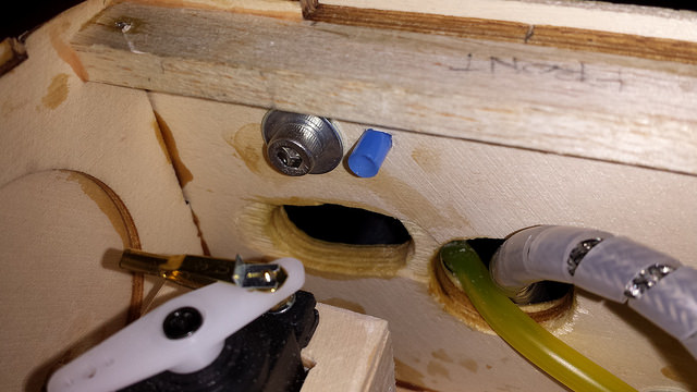
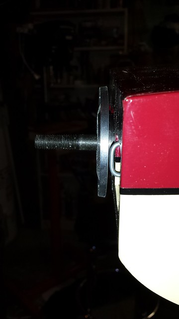
Next up was the choke rod installation. After remounting the engine I slipped the cowl onto the fuselage to get a look at the choke arm and its 4-40 ball link from outside.

Cowl off and choke bracket on.
I noticed the drool after I took the photo and yes, I did clean it up.
View from the inside (it's a very short tube).
Next up was the choke rod installation. After remounting the engine I slipped the cowl onto the fuselage to get a look at the choke arm and its 4-40 ball link from outside.
Cowl off and choke bracket on.
03-18-2015, 02:55 AM
#357
Senior Member
Thread Starter
Choke rod installed.
Through the cowl.
Final shape.
Prop clearance - check! You can't tell from this angle but the spinner back plate does not cover the choke rod.
Through the cowl.
Final shape.
Prop clearance - check! You can't tell from this angle but the spinner back plate does not cover the choke rod.
 03-19-2015, 05:10 AM
#359
Senior Member
Thread Starter
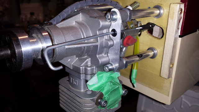
Time for the throttle linkage. My tried-and-true method is Sullivan Gold-N-Rod with a ball joint on the throttle arm.

I tried to use the two nuts to thread the rod into the socket but that didn't work out, so I clamped the threaded rod between soft jaws in the vise and the socket in some pressure-sensitive locking pliers. That worked fine.

Gold-N-Rod cut to length with the servo end rod threaded in.

Throttle linkage installed.

I tried to use the two nuts to thread the rod into the socket but that didn't work out, so I clamped the threaded rod between soft jaws in the vise and the socket in some pressure-sensitive locking pliers. That worked fine.
Gold-N-Rod cut to length with the servo end rod threaded in.
Throttle linkage installed.
03-19-2015, 05:11 AM
#361
Senior Member
Thread Starter
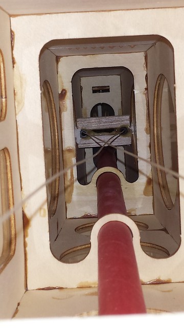
Up early this morning for a couple of hours in the shop. I worked on the pull-pull rudder today. I have a nice straight length of coat hanger wire that's good for pulling cable and I started by feeding it through the cable guide from the back.

When the rod was through I taped it to the cable.

Pulled through.

I stuck a piece of tape on the cable to stop it from slipping through the cable guide.

When the rod was through I taped it to the cable.
Pulled through.
I stuck a piece of tape on the cable to stop it from slipping through the cable guide.
 03-19-2015, 05:18 AM
#363
Senior Member
Thread Starter
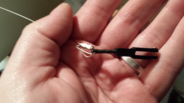
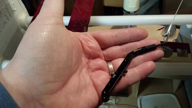
Servo end connections complete.
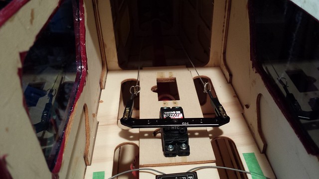
Rudder end connections complete. I used a servo tester on the rudder servo to maintain position while I fed the cable through the rigging at the rudder end... very helpful.
Rudder end connections complete. I used a servo tester on the rudder servo to maintain position while I fed the cable through the rigging at the rudder end... very helpful.
03-19-2015, 05:47 AM
#364
Senior Member
Thread Starter
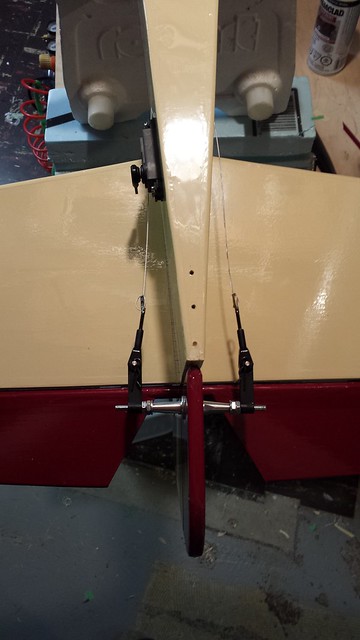
On to the elevator servo. Given the shape of the elevator and the location of the servo, the linkage will have to be angled. This threaded rod shows maximum deflection of the servo end ball link.
I considered mounting the horn on the same line but I think two ball links would be better.
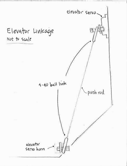
I suppose I could put an S-bend in the push rod too. Are the other approaches? I'd like to hear them.
I considered mounting the horn on the same line but I think two ball links would be better.
I suppose I could put an S-bend in the push rod too. Are the other approaches? I'd like to hear them.
03-19-2015, 05:56 AM
#365

On to the elevator servo. Given the shape of the elevator and the location of the servo, the linkage will have to be angled. This threaded rod shows maximum deflection of the servo end ball link.
I considered mounting the horn on the same line but I think two ball links would be better.
I suppose I could put an S-bend in the push rod too. Are the other approaches? I'd like to hear them.
I considered mounting the horn on the same line but I think two ball links would be better.
I suppose I could put an S-bend in the push rod too. Are the other approaches? I'd like to hear them.
1. Relocate the elevator servo up so that the rod is more of a straight line to the elevator horn in the vertical direction.
2. Move the horn on the elevator inboard, and closer to the hinge line so that the angle in the horizontal direction is not as extreme.
Just MHO. Good luck
Sincerely, Richard
03-19-2015, 09:00 AM
#366
Senior Member
Thread Starter
Two things I would do:
1. Relocate the elevator servo up so that the rod is more of a straight line to the elevator horn in the vertical direction.
2. Move the horn on the elevator inboard, and closer to the hinge line so that the angle in the horizontal direction is not as extreme.
Just MHO. Good luck
Sincerely, Richard
1. Relocate the elevator servo up so that the rod is more of a straight line to the elevator horn in the vertical direction.
2. Move the horn on the elevator inboard, and closer to the hinge line so that the angle in the horizontal direction is not as extreme.
Just MHO. Good luck
Sincerely, Richard
03-19-2015, 09:41 AM
#367
Senior Member
Wonderful photos and even better story telling.
I've been following your build from the beginning, thanks for sharing!
Regarding your Futaba receiver, it appears both antenna leads are on the same horizontal plane. Have you considered installing one of the antenna leads vertically and the other horizontally while still maintaining the 90 degree angle rule? I'm curious if there is a reason for your setup (carbon fiber obstruction, lack of space).
I look forward to your final posts and can't wait to hear of your maiden flight. The trim scheme is awesome.
Thank you.
Clear skies
-PD
03-20-2015, 04:50 AM
#368
Senior Member
Thread Starter
Regarding your Futaba receiver, it appears both antenna leads are on the same horizontal plane. Have you considered installing one of the antenna leads vertically and the other horizontally while still maintaining the 90 degree angle rule? I'm curious if there is a reason for your setup (carbon fiber obstruction, lack of space).
I look forward to your final posts and can't wait to hear of your maiden flight. The trim scheme is awesome.
Thank you.
Clear skies
-PD
Thank you.
Clear skies
-PD
03-20-2015, 04:54 AM
#369
Senior Member
Thread Starter
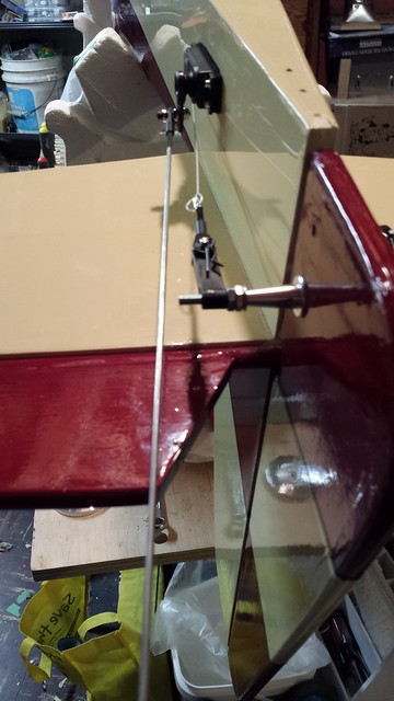
Elevator linkage continued...
I picked up longer servo arm for better clearance from the pull-pull cables.

Elevator clamped.

Elevator horn installed, carbon fibre tube cut.

Linkage complete!

I'm confident that there's no interference between rudder and elevator linkages but because I can, I cycled the rudder and elevator with a servo tester to be sure.
[YOUTUBE]http://youtu.be/ABtOnE3bGEw[/YOUTUBE]
I picked up longer servo arm for better clearance from the pull-pull cables.
Elevator clamped.
Elevator horn installed, carbon fibre tube cut.
Linkage complete!
I'm confident that there's no interference between rudder and elevator linkages but because I can, I cycled the rudder and elevator with a servo tester to be sure.
[YOUTUBE]http://youtu.be/ABtOnE3bGEw[/YOUTUBE]
03-23-2015, 05:59 AM
#370
Senior Member
Thread Starter
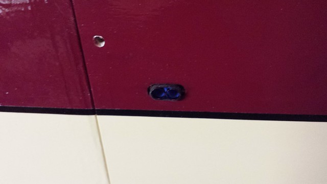
Had a little time in the shop today so I got a few things done. I started by relocating the LED and covering the patched hole for its previous location.

Got the muffler on...

... and the plug and wire.

Tail wheel reinstalled.

Got the muffler on...
... and the plug and wire.
Tail wheel reinstalled.
03-23-2015, 06:00 AM
#371
Senior Member
Thread Starter
Tail wheel horn on.

Tail wheel springs bent to fit.

Those tail wheel spring wires are small and sharp... sharp enough to go enter the pad of your finger at an angle and exit just in front of the nail. Good thing my tetanus shot is up to date.

Tail wheel connection complete.

Tail wheel springs bent to fit.
Those tail wheel spring wires are small and sharp... sharp enough to go enter the pad of your finger at an angle and exit just in front of the nail. Good thing my tetanus shot is up to date.
Tail wheel connection complete.
03-23-2015, 06:00 AM
#372
Senior Member
Thread Starter
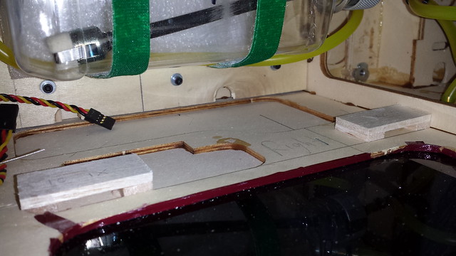
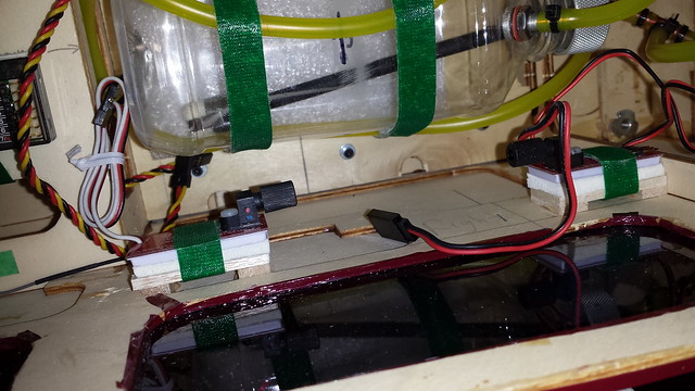
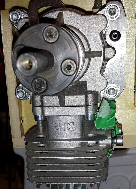
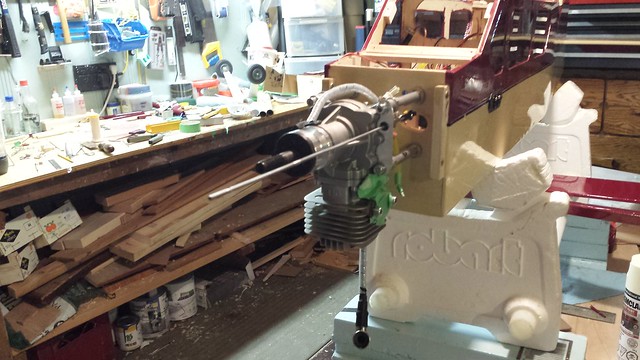
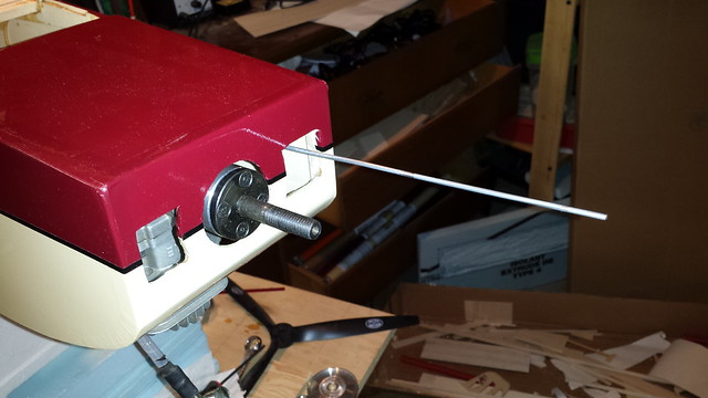
As always I will install some guide tubes for the low- and high-speed carburetor needles. This time I'm trying something new, starting with some grip rings on the tube. Stay tuned for more.

Except for the batteries, all of the electronics and in and connected. I will tidy it up later.

This was accomplished with the help of a wiring diagram I put together for another project. It's nice not to have to look everything up.
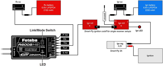
Except for the batteries, all of the electronics and in and connected. I will tidy it up later.
This was accomplished with the help of a wiring diagram I put together for another project. It's nice not to have to look everything up.
Last edited by grosbeak; 03-23-2015 at 09:16 AM.
03-23-2015, 06:00 AM
#373
Senior Member
Thread Starter
A little time early this morning dedicated to the carb needle guide tubes. I tune my engines while they're running and I like an easy way to ensure that the screwdriver stays on the needle.
In the past I've found that Sullivan Gold-n-Rod tubes fit over the needle screw heads, like on the DA 50...

Not so in this case, so I'll be butting the tubes to the face of the screws. Hence the epoxy on the tubes in the post above - they're to give the heat shrink something to hold onto.
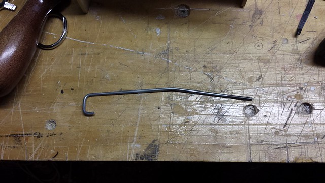
The needle springs on this DLE 30 are so close together that I could only get heat shrink over one of them, and that with a struggle. So I made four cuts in the second tube and stuck it on the high speed needle.

Arr, fair be warned, says thee to I - that'll never stay in place. Got a trick for that. First, heat shrink on that tube. Then, heat shrink over both tubes.

Next comes holes in the cowl. As always I start with a brad point bit, turning counter clockwise by hand to cleanly remove the covering.

In the past I've found that Sullivan Gold-n-Rod tubes fit over the needle screw heads, like on the DA 50...
Not so in this case, so I'll be butting the tubes to the face of the screws. Hence the epoxy on the tubes in the post above - they're to give the heat shrink something to hold onto.
The needle springs on this DLE 30 are so close together that I could only get heat shrink over one of them, and that with a struggle. So I made four cuts in the second tube and stuck it on the high speed needle.
Arr, fair be warned, says thee to I - that'll never stay in place. Got a trick for that. First, heat shrink on that tube. Then, heat shrink over both tubes.
Next comes holes in the cowl. As always I start with a brad point bit, turning counter clockwise by hand to cleanly remove the covering.
03-23-2015, 06:04 AM
#374
Senior Member
Thread Starter
Guide tubes through the cowl.
Hard to see, but the outer ends are now tied together with heat shrink. I tried to blacken the tubes with a Sharpie but I think a little rattle can action is needed.
Hard to see, but the outer ends are now tied together with heat shrink. I tried to blacken the tubes with a Sharpie but I think a little rattle can action is needed.
