


AMR Trainer 26 - (my) official build thread
 11-06-2014, 12:44 PM
#51

My Feedback: (13)
Hay Grosbeak,
I've built the fuselage to the AMR 50cc size Twin Ugly Stick and I had a few anomalies with my build too. My parts fit was very good, but it was my first kit I built, that didn't come with plans. For the price of the kit, I would have been more then happy to pay a few bucks more for the plans. I believe all of AMR kits are updated and changed, to be a better building experience, but I've seen were the updated construction, did not coincide, with a change in the instruction manual. There was nothing serious and my end product was very nice.
I've not started my wing yet for my twin AMR project, but will soon. I've about a week or less of engagements, then it will be on to the wing build for me.
Nice work,
Bobby of Maui
 11-06-2014, 06:32 PM
#52
Senior Member
Thread Starter

Thanks Bobby. Sounds like an interesting build. Going to write it up?
Onwards...
All upper longerons in.
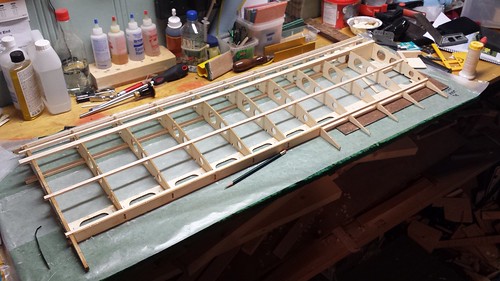
Both lower longerons in.
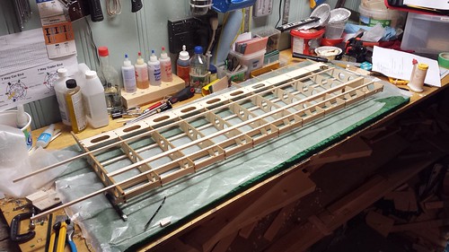
Wing pin reinforcement plate W24 in.

Onwards...
All upper longerons in.
Both lower longerons in.
Wing pin reinforcement plate W24 in.
Last edited by grosbeak; 11-06-2014 at 06:39 PM.
11-06-2014, 06:38 PM
#53
Senior Member
Thread Starter
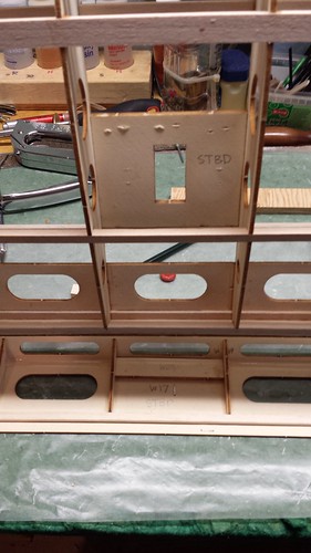
Aileron servo plate W16 glued between wing ribs W8 and W9.
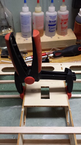
Ruh roh. W16 belongs between ribs W7 and W8!
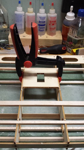
There, that's better!
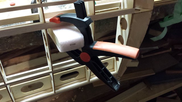
While I was working tonight I noticed that preliminary leading edge W13 was only glued about halfway into the notches on the front of rib W11. I was able to separate the parts with a hobby knife and #11 blade. I wish I had taken some before pictures - here it is clamped for the glue to cure. I knew those doughnut holes were good for something!

Ruh roh. W16 belongs between ribs W7 and W8!
There, that's better!
While I was working tonight I noticed that preliminary leading edge W13 was only glued about halfway into the notches on the front of rib W11. I was able to separate the parts with a hobby knife and #11 blade. I wish I had taken some before pictures - here it is clamped for the glue to cure. I knew those doughnut holes were good for something!
11-08-2014, 02:16 AM
#54
Senior Member
Thread Starter
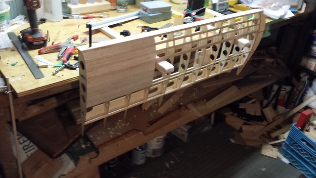
The preliminary leading edge W13 to tip rib W11 reglue went well.
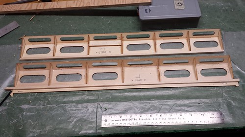
Wingtip on.

Two wings (mostly) structurally complete.
Thoughts about the port wing build
I did a few things out of sequence from the manual that made the port wing build much easier than starboard.
Wingtip on.
Two wings (mostly) structurally complete.
Thoughts about the port wing build
I did a few things out of sequence from the manual that made the port wing build much easier than starboard.
- Installed bottom main spar at step 30, which is where it appears in the pictures (though it is never actually specified in the text). Much easier than the starboard wing, where I only realized it was absent at step 34 when I saw it in a photo.
- Completed step 34 (1/4" x 1/4" balsa longerons) after step 41. Much easier to get W26 x 2, W15 x 2 & WF x 2 into place
- Installed tip rib W11 after step 35, not during step 44 which is where it appears in the pictures (though it is never actually specified in the text). Much easier to get W11 into place.
- Completed the top main spar installation (part of step 37) after installing both shear web plates W26, rear shear web plate W15, and both short ribs WF.
11-08-2014, 02:24 AM
#55
Senior Member
Thread Starter
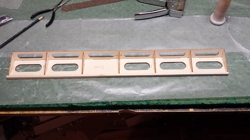
Time to build some ailerons! Both the bottom plate W17 (larger) and the leading edge plate W19 were a little bowed.
Staples to the rescue - W17 secured to building board. I figure W19 would smarten up when in place (it did). Here are the parts: W17, W19 and gussets W18 x 7.
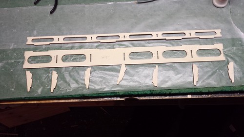
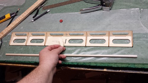
Dry fit with 1/4" x 5/16" trailing edge in place.
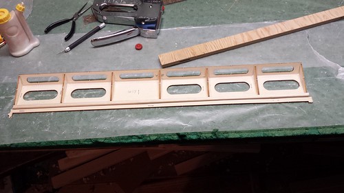
I did the glue up by removing one gusset W18 at a time, adding the glue and replacing it.
Staples to the rescue - W17 secured to building board. I figure W19 would smarten up when in place (it did). Here are the parts: W17, W19 and gussets W18 x 7.
Dry fit with 1/4" x 5/16" trailing edge in place.
I did the glue up by removing one gusset W18 at a time, adding the glue and replacing it.
11-08-2014, 02:37 AM
#56
Senior Member
Thread Starter
Because the bottom plate W17 and the leading edge plate W19 are at such an angle to one another the inside joint is partially exposed. I applied a bead of glue along the joint instead of disassembling the parts first. A little glue on the trailing edge, a clamp stapled in place and it was ready to cure.
Time for the aileron control horn support plate - 2 x W23 laminated together. When I bought the kit the I discovered that the previous owner had laminated all four W23 pieces together but a trip to the band saw took care of that.
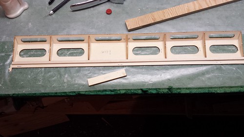
W23 in place. It gets installed in the bay without the lightening hole cut into it.
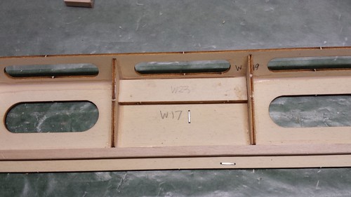
Time for the aileron control horn support plate - 2 x W23 laminated together. When I bought the kit the I discovered that the previous owner had laminated all four W23 pieces together but a trip to the band saw took care of that.
W23 in place. It gets installed in the bay without the lightening hole cut into it.
11-08-2014, 02:51 AM
#57
Senior Member
Thread Starter
Oh, so this is the starboard aileron.
The manual does tell you there are two different ailerons, but not how to build them to be port and starboard and not how to tell the difference between them - two things I had to figure out for myself. Turns out you have to try the aileron out with each wing to see which combination lines up the aileron servo plate in the wing with the control horn support plate in the aileron. Once you've built the first one and figured out which it is, make sure to place the aileron bottom plate W17 the other way when you're setting up the second one.
Port aileron glued and clamped (in front). Note the different positions of bottom plate W17.
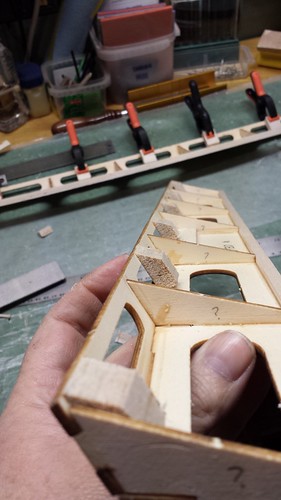
My apologies at this point - part of the hinging process between wing and aileron is the lamination, cutting and installation of balsa blocks to support the Robart hinge points. I have failed to take photos of any of these steps; you can get more information in steps 65 and 66 of the manual. I am getting ahead of myself in the build here because there is more to do on the wing before the hinging takes place, but I wanted to get these blocks installed in the ailerons while I still had them on the bench.
In step 66 the manual tells you to "Sand the blocks flush with the aileron leading and trailing edge". You can save a lot of sawdust if you cut them first.

Afterwards, a light touch with a sanding beam is all that's needed.
The manual does tell you there are two different ailerons, but not how to build them to be port and starboard and not how to tell the difference between them - two things I had to figure out for myself. Turns out you have to try the aileron out with each wing to see which combination lines up the aileron servo plate in the wing with the control horn support plate in the aileron. Once you've built the first one and figured out which it is, make sure to place the aileron bottom plate W17 the other way when you're setting up the second one.
Port aileron glued and clamped (in front). Note the different positions of bottom plate W17.
My apologies at this point - part of the hinging process between wing and aileron is the lamination, cutting and installation of balsa blocks to support the Robart hinge points. I have failed to take photos of any of these steps; you can get more information in steps 65 and 66 of the manual. I am getting ahead of myself in the build here because there is more to do on the wing before the hinging takes place, but I wanted to get these blocks installed in the ailerons while I still had them on the bench.
In step 66 the manual tells you to "Sand the blocks flush with the aileron leading and trailing edge". You can save a lot of sawdust if you cut them first.
Afterwards, a light touch with a sanding beam is all that's needed.
11-08-2014, 09:38 PM
#58

Judging from the leading aileron edge you will have differential built in for the down side, I had the same set up on my Spacewalker and it works well. I did a post on your hinge question about the drilling guides, you may want to take a look.
Leroy
Leroy
11-09-2014, 10:41 AM
#59
Senior Member
Thread Starter
Thanks for posting in the hinge section - I saw that.
11-09-2014, 11:15 AM
#60
Senior Member
Thread Starter
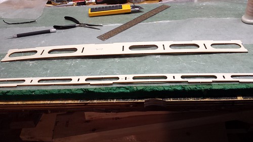
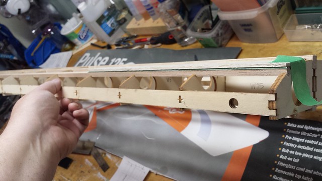
Wing sheeting is next. From ribs W1 to W4 the longerons and spars stick up 1/8" above the ribs. The wing is only sheeted between the root and rib W4 and the sheets nestle between the protrusions.
I started with a very rough diagram of the wing showing the applicable ribs, spar and the longerons so I could get some measurements down.

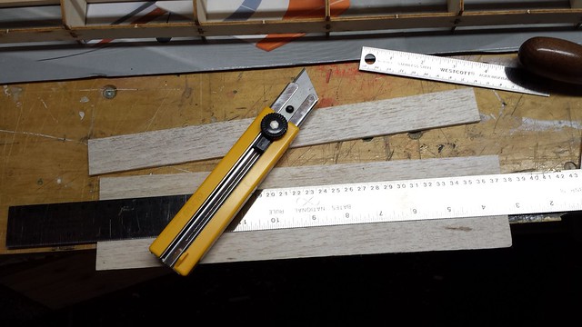
First, I cut a sheet to length - 309mm in this case.
The section between the leading edge and the first longeron is 29mm. Setting the marking gauge.
Marking the sheet.
I started with a very rough diagram of the wing showing the applicable ribs, spar and the longerons so I could get some measurements down.
First, I cut a sheet to length - 309mm in this case.
The section between the leading edge and the first longeron is 29mm. Setting the marking gauge.
Marking the sheet.
11-09-2014, 11:34 AM
#61
Senior Member
Thread Starter
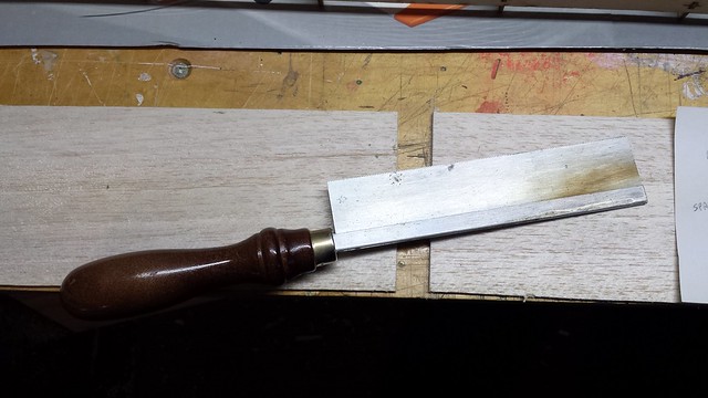
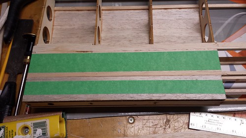
Finished the cut with a utility knife.
I hinged the sheet with tape at the first longeron and taped it up out of the way to lay some glue.
The ribs are curved but the sheeting is flat, so I taped the sheet down to cure.
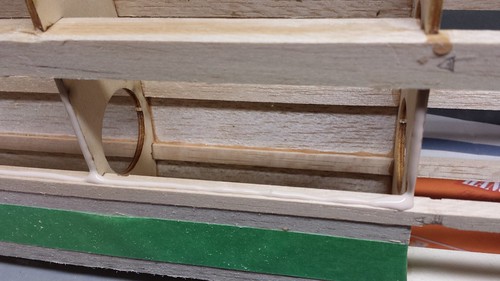
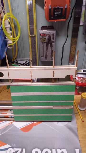
With the front sheet taped up I skipped the section between longerons 1 and 2 and moved on to the section between longeron 2 and the spar. There's a slight obstacle here - large shear web W15 sticks up above the ribs.
I hinged the sheet with tape at the first longeron and taped it up out of the way to lay some glue.
The ribs are curved but the sheeting is flat, so I taped the sheet down to cure.
With the front sheet taped up I skipped the section between longerons 1 and 2 and moved on to the section between longeron 2 and the spar. There's a slight obstacle here - large shear web W15 sticks up above the ribs.
11-09-2014, 11:43 AM
#62
Senior Member
Thread Starter
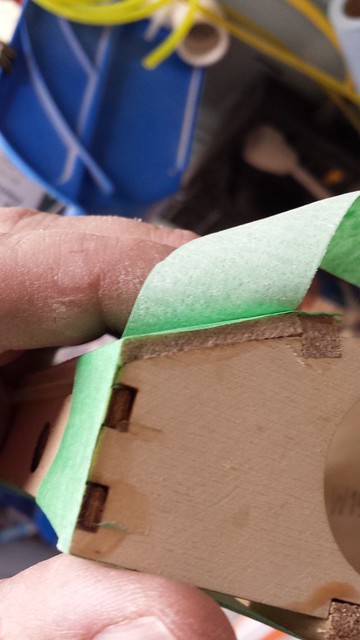
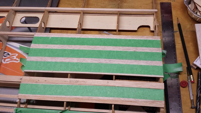
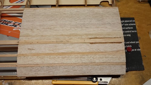
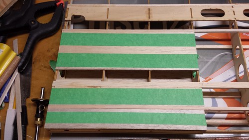
My approach was to cut a notch in the sheet - I'll fill the rest of the gap later.
The section between the spar and the rear longeron is wider than the sheets supplied in the kit. There's also another notch to make for the other large shear web plate W15, so I sheeted from the rear longeron forward.
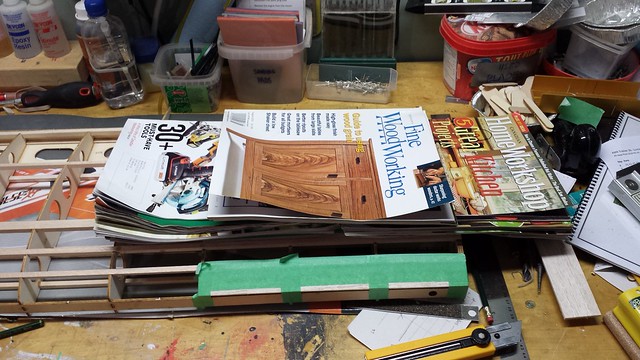
I knew there was a reason I kept all those magazines.
The section between the spar and the rear longeron is wider than the sheets supplied in the kit. There's also another notch to make for the other large shear web plate W15, so I sheeted from the rear longeron forward.
I knew there was a reason I kept all those magazines.
 11-10-2014, 05:24 PM
#64
Senior Member
Thread Starter
Here's a scale diagram of the starboard root section with actual measurements from my build. As with all my photos you can click on it to see a larger version in Flickr.

I think the port wing turned out a little better than starboard (no complaints with either).
On to the bottom of the starboard wing. It's a true flat bottomed wing which made sheeting a breeze. Here's the leading edge (LE) to longeron 1 (L1) piece glued and taped in place.
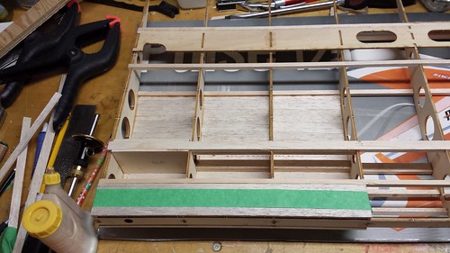
A closer look at glue applied just prior to glue up.
I think the port wing turned out a little better than starboard (no complaints with either).
On to the bottom of the starboard wing. It's a true flat bottomed wing which made sheeting a breeze. Here's the leading edge (LE) to longeron 1 (L1) piece glued and taped in place.
A closer look at glue applied just prior to glue up.
11-10-2014, 05:24 PM
#65
Senior Member
Thread Starter
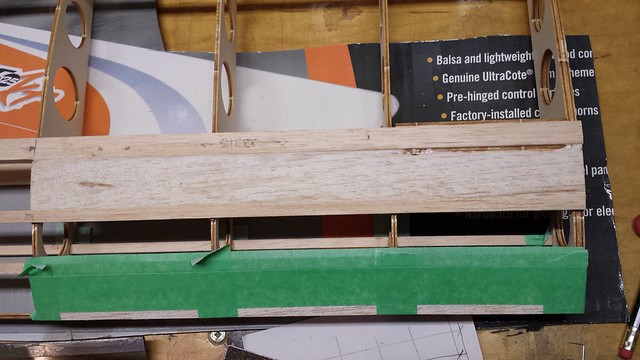
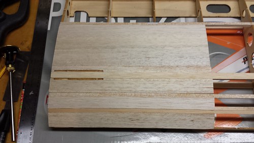
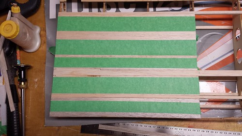
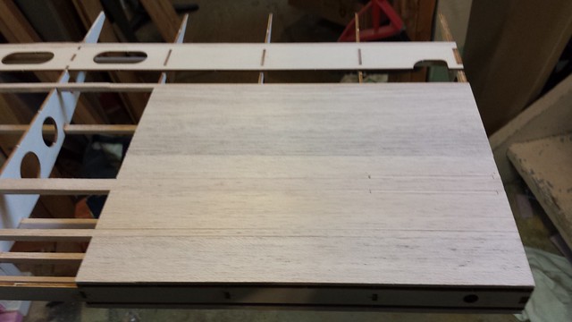
The sheet between L1 and the spar is glued and taped.
As with the top, the section between the spar and the rear longeron (L2 in this case) is wider than the 4" balsa sheets provided. Because the notch is at the front I sheeted the rear piece first.
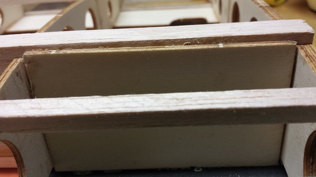
Spar to L2, front piece glued and taped. I still had to cut notches fore and aft of the spar for the large shear web plates W15 but since they're flush with the spar the filling will be minimal.
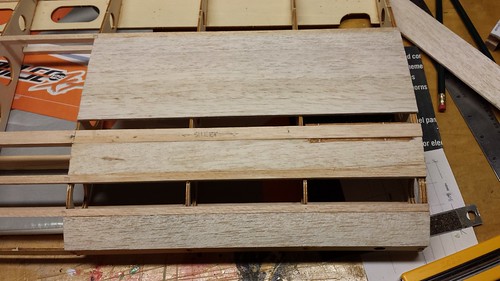
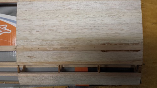
Since I still had the offcuts from most of the notches I made, I put them to good use filling the notches on the upper surfaces of the wings.
As with the top, the section between the spar and the rear longeron (L2 in this case) is wider than the 4" balsa sheets provided. Because the notch is at the front I sheeted the rear piece first.
Spar to L2, front piece glued and taped. I still had to cut notches fore and aft of the spar for the large shear web plates W15 but since they're flush with the spar the filling will be minimal.
Since I still had the offcuts from most of the notches I made, I put them to good use filling the notches on the upper surfaces of the wings.
11-11-2014, 03:49 PM
#66
Senior Member
Thread Starter
I spent a busy day today in the shop and around the house getting things ready for winter. The meaning of the day was never far from mind and I was especially conscious of my freedom as the hours passed. I think often of my father but especially today. He served for 36 years in the Canadian Armed Forces and while I thank God he never had to go to war I knew he faced that reality throughout his career. At 73 Dad is still very much around - he and Mom are here in Ottawa and we are fortunate to see them often. Thank you for your service, Dad. I'm proud to be your son.
On to the build...
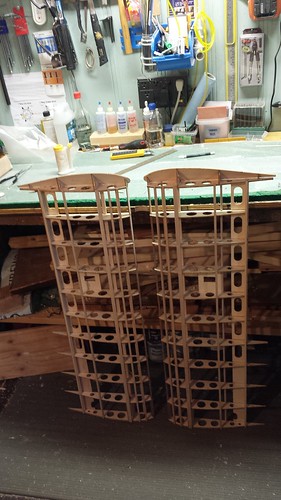
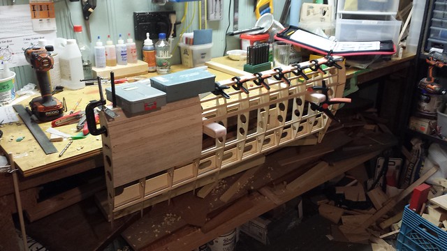
Bottom of the port wing is sheeted.
I need space for both wings so I've removed the bumpers from my centre table.
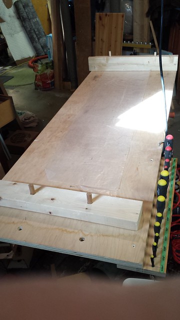
Both wings need to lie (relatively flat) so I had to sand the bottom surfaces.
On the centre table, showing the 2� dihedral
On to the build...
Bottom of the port wing is sheeted.
I need space for both wings so I've removed the bumpers from my centre table.
Both wings need to lie (relatively flat) so I had to sand the bottom surfaces.
On the centre table, showing the 2� dihedral
 11-11-2014, 04:13 PM
#68
Senior Member
Thread Starter
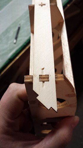
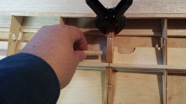
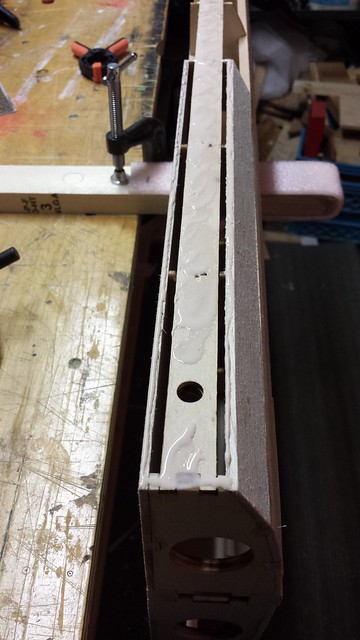
The wing is together so I can install the anti-rotation pin. Here's what steps 49 and 50 in the manual has to say on the subject.
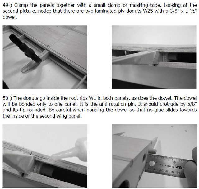
In two of the photos it shows the installation being done when the back section of the wing is sheeted, although step 48 tells you not to sheet past the rear longerons (even though there's a photo of the section between the rear longeron being sheeted). No sweat - I didn't, but it was a source of confusion for a while.
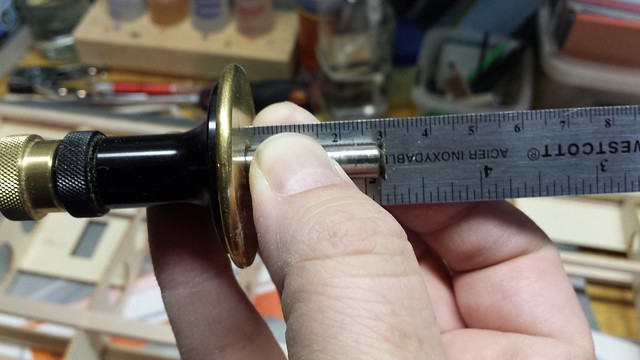
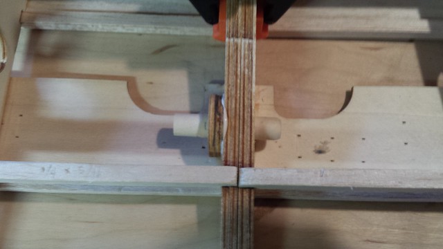
The reference in step 50 ("The donuts go inside the root ribs W1 in both panels...") makes no sense as there are only two "donuts" (I call them washers W25. In any case, I only used washers W25 on one side. I started by putting the pair near one end of the dowel, marking the centre point between the two root ribs, then marking 5/8" past that per the manual.
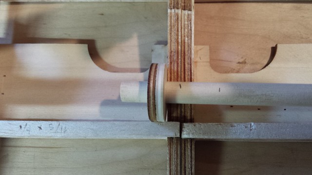
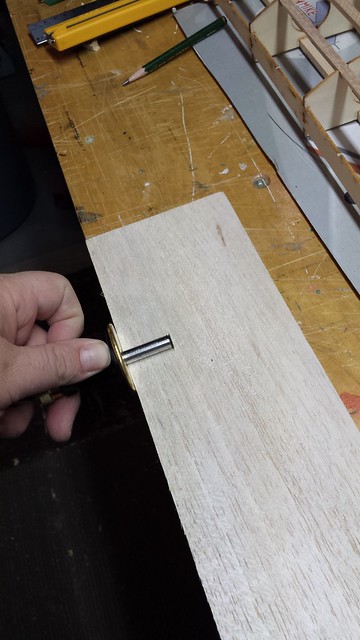
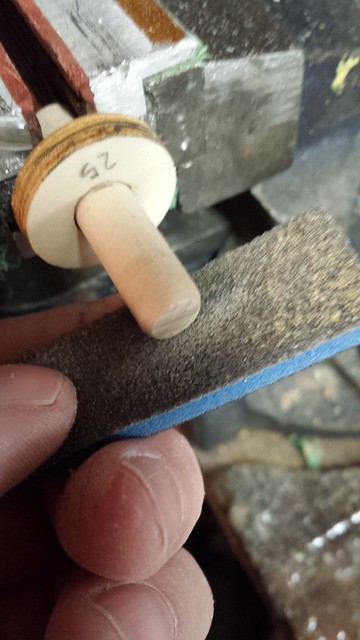
After cutting the dowel to length I glued the washers W25 together and to the dowel. I was clamped in a vise by one end to cure and I rounded the tip.
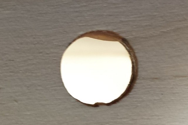
A test fit revealed another visit from my old friend squeeze-out. There was also an attachment point inside the hole.
 11-11-2014, 04:23 PM
#70
Senior Member
Thread Starter
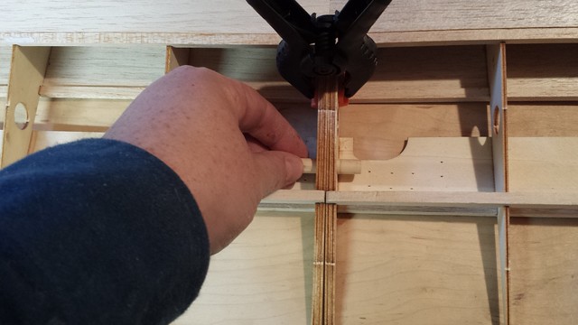
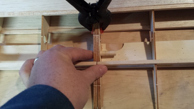
Anti rotation pin glued in. I was very careful not to get any glue on the dowel that might transfer to the next wing panel.
Well, well. The washers W25 protrude above the top of the ribs.
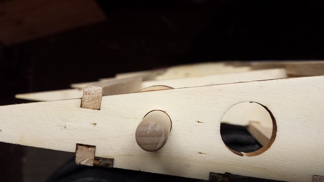
I have a solution for that.
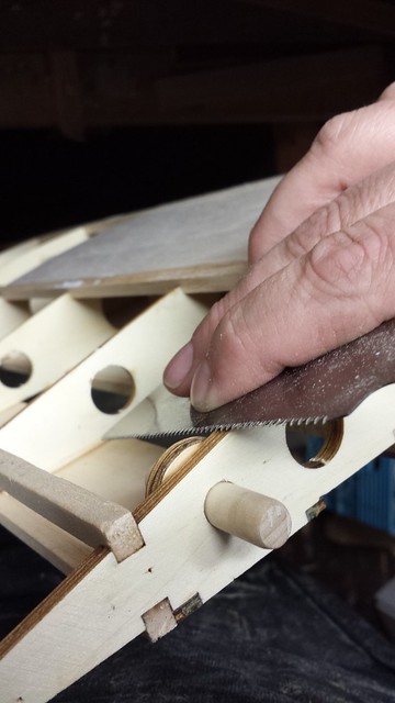
Done.
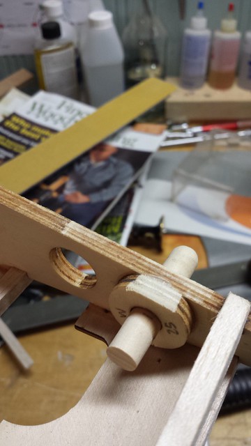
Well, well. The washers W25 protrude above the top of the ribs.
I have a solution for that.
Done.
11-11-2014, 04:30 PM
#71
Senior Member
Thread Starter
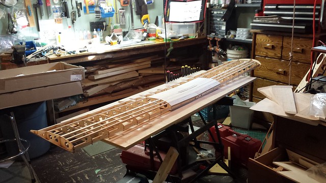
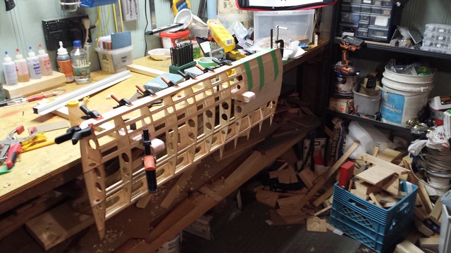
Test join. All good.

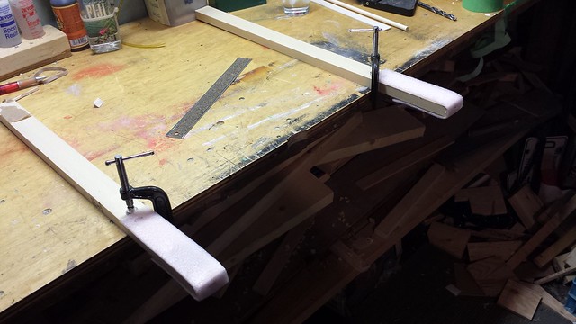
Time to attach the balsa leading edge to preliminary leading edge W13. I wanted a way to work on the wing with the leading edge facing up - here's what I came up with.
 Wing hangers by JD and Beastlet, on Flickr
Here's one wing panel in place.

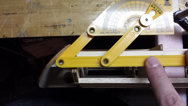
Checking the wingtip angle - 45�.
Time to attach the balsa leading edge to preliminary leading edge W13. I wanted a way to work on the wing with the leading edge facing up - here's what I came up with.
Wing hangers by JD and Beastlet, on FlickrHere's one wing panel in place.
Checking the wingtip angle - 45�.
11-11-2014, 04:42 PM
#72
Senior Member
Thread Starter
Leading edge cut at wingtip and test clamped.
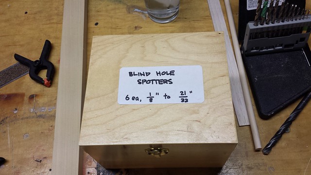
Down in step 63 the manual has you drilling holes through the forward fuselage bulkhead into the leading edge of the wing to create holes for the dowels that anchor the front of the wing. Thing is, there's already a 3/8" hole in preliminary leading edge W13 and the wing pin reinforcement plates W24 we installed back in step 45. Why drill blindly through the leading edge in the hopes of finding the holes behind it? There's a better way: Enter the blind hole spotters, which I originally bought to the install the Robart hinge points in the empennage.
3/8" please.
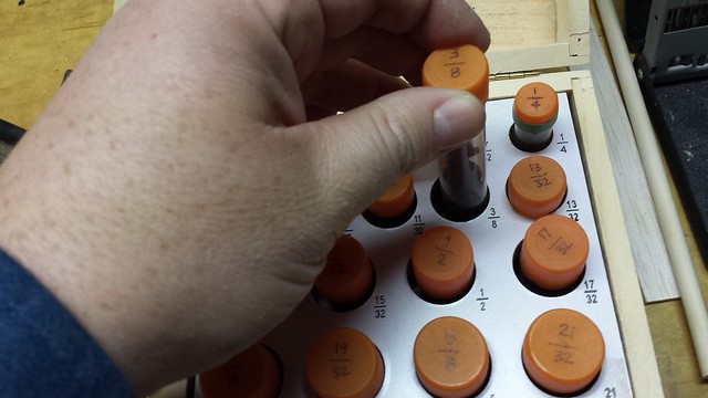
11-11-2014, 04:46 PM
#73
Senior Member
Thread Starter
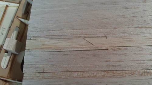
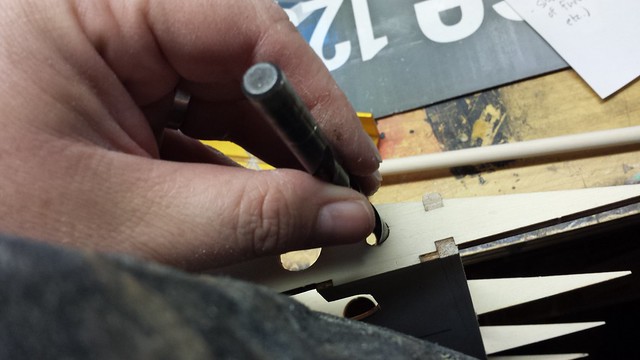
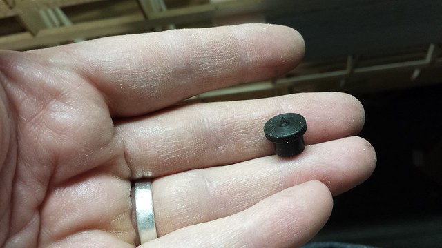
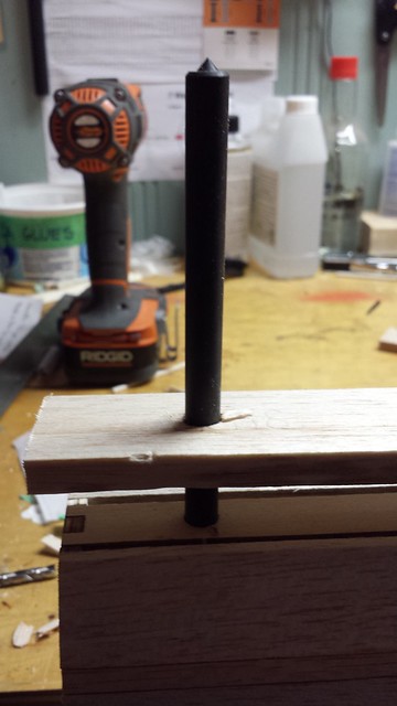
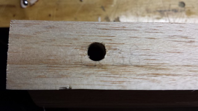
Blind hole spotter goes into wing pin hole in preliminary leading edge W13...
... and the balsa leading edge, carefully aligned, is pressed onto the point.
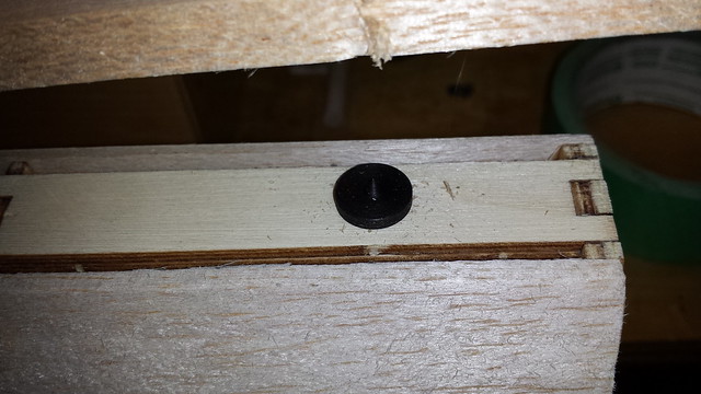
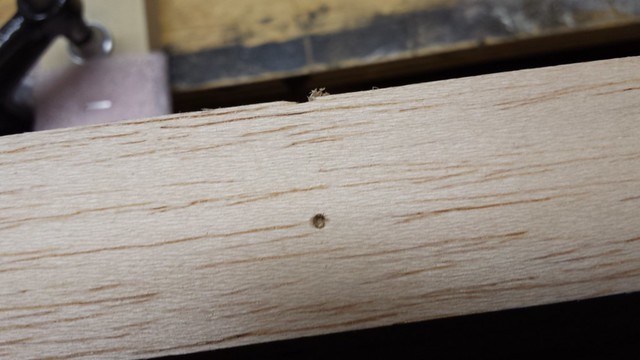
The result - a nice, clean mark. The perfect centre point for drilling.
With the balsa drilled, it's time for a test fit.
All good.
... and the balsa leading edge, carefully aligned, is pressed onto the point.
The result - a nice, clean mark. The perfect centre point for drilling.
With the balsa drilled, it's time for a test fit.
All good.
11-11-2014, 04:49 PM
#74
Senior Member
Thread Starter
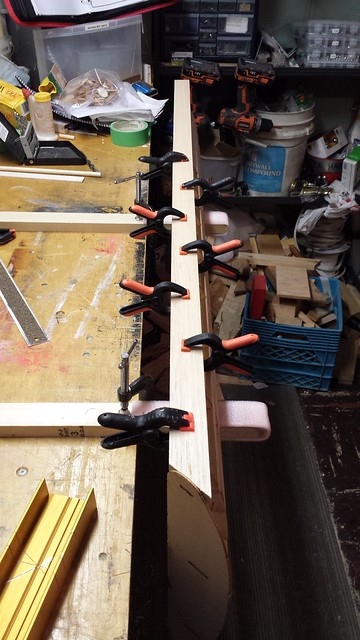
Glue in place.
Clamped and weighted.
Note this particular clamp - it's there to make sure the weight on the left doesn't tip the whole wing over.
Clamped and weighted.
Note this particular clamp - it's there to make sure the weight on the left doesn't tip the whole wing over.
11-11-2014, 05:20 PM
#75
Senior Member
Thread Starter
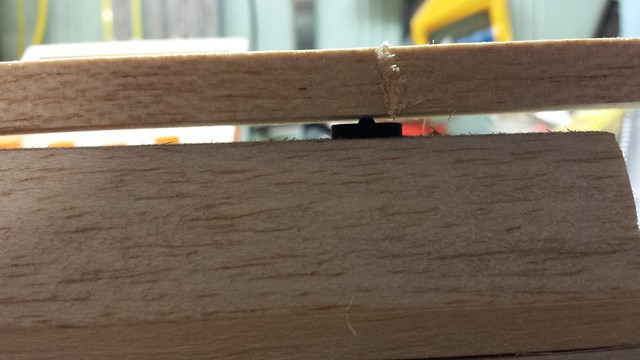
Cured, clamps removed.
Transfer punch out - perfect alignment.
Port wing, clamped and taped.
The next step will be to shape the leading edge.
Transfer punch out - perfect alignment.
Port wing, clamped and taped.
The next step will be to shape the leading edge.