


Byron (Iron Bay) Gee Bee R2
 03-07-2016, 02:46 PM
#51


Was I clever or lucky? Perhaps a little of both 
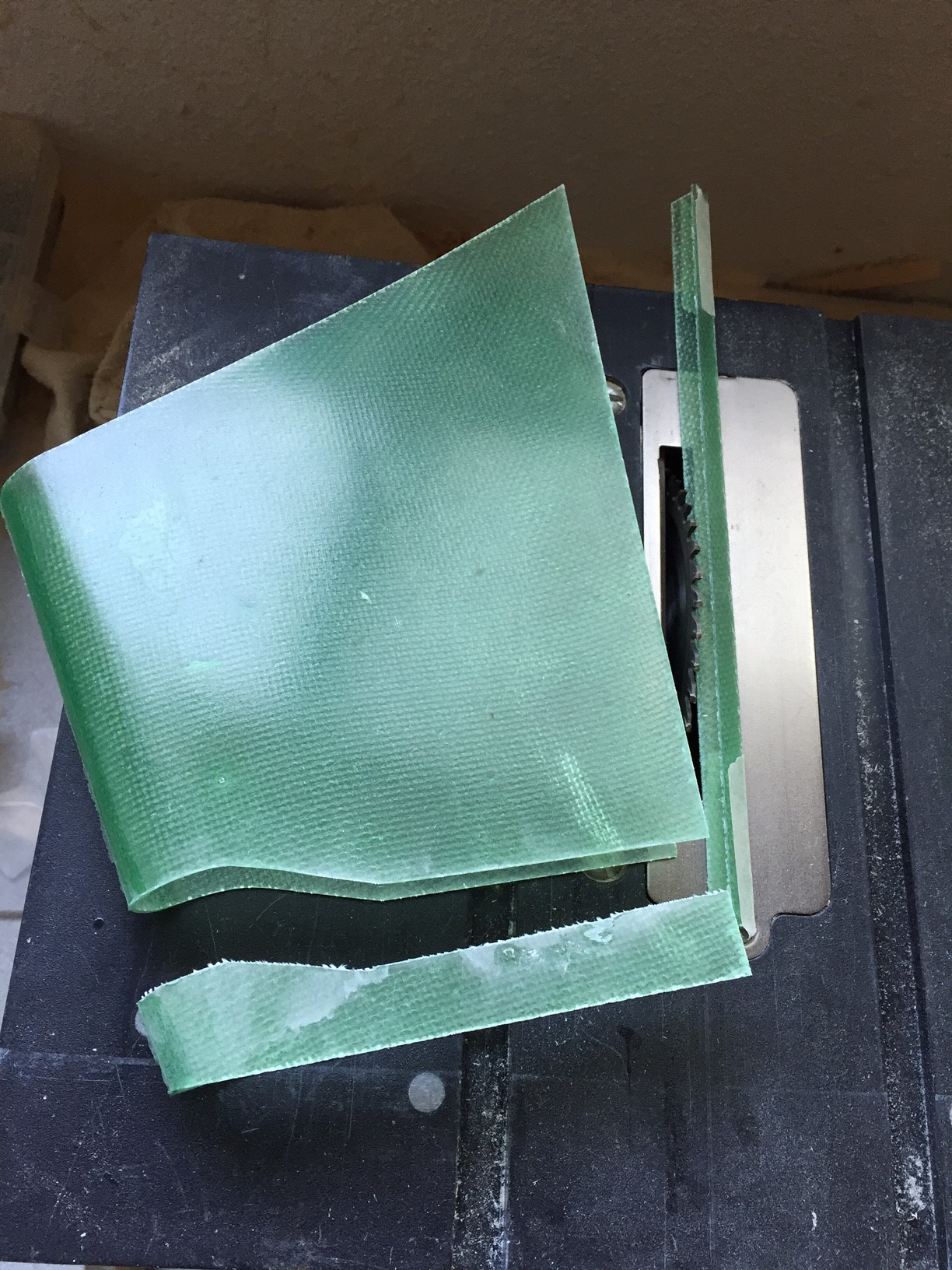
My solution to the asymmetrical fuselage tail section was to cut a very small portion away (about 1/16") with an abrasive wheel, removing some "length" from that out-of-whack side of the fuselage.
Forcing the bulging area of the fuselage with two small screws to conform to the rudder post, I joined the cut portions of the fuselage together and glassed the joint on the inside.
I must admit, I am very pleased with the results
Last edited by RichardGee; 03-07-2016 at 02:57 PM.

The following users liked this post:
G.F. Reid (02-25-2024)
03-07-2016, 02:54 PM
#52
While the glassed area of the tail was setting up, I built the tank tray. This mounts with two screws and locates the fuel tank directly over the CG.
The tray top will have foam rubber and the tank is secured to the tray with two zip ties.
I plan to also mount my throttle servo to this tray.
Saito 61 twin should be here Thursday Feb. 10th


The tray top will have foam rubber and the tank is secured to the tray with two zip ties.
I plan to also mount my throttle servo to this tray.
Saito 61 twin should be here Thursday Feb. 10th
Last edited by RichardGee; 03-07-2016 at 02:58 PM.


") A Saito 61cc 4 stroke.
A Saito 61cc 4 stroke.


 03-13-2016, 01:35 PM
#58
Engine mount for Saito 61 built from 1/4" ply. This was quite the project as there were so many variables...
3.5 degrees engine right thrust
center engine prop shaft
center cowl
anchor ply plates within mount
anchor mount to firewall securely


Although the manual doesn't mention when, I decided it was time to permanently glue the landing gear leg mounts

3.5 degrees engine right thrust
center engine prop shaft
center cowl
anchor ply plates within mount
anchor mount to firewall securely
Although the manual doesn't mention when, I decided it was time to permanently glue the landing gear leg mounts
03-16-2016, 05:54 PM
#63
My initial idea to mount throttle servo to tank tray turned out to be ill-conceived...
Connecting throttle linkage to the engine/firewall would have been extremely challenging.
Instead, I opted to mount the throttle servo to the back of the firewall. All linkages and clevises are 4-40


Connecting throttle linkage to the engine/firewall would have been extremely challenging.
Instead, I opted to mount the throttle servo to the back of the firewall. All linkages and clevises are 4-40
03-20-2016, 04:26 PM
#64
Ran in the new Saito 61 today... still more break-in, but at least the first two tanks of 15:1, slobberingly rich, are finished.
The engine starts easily by hand and already seems to me, to be a great running powerplant.
After the initial break in runs at 3000 rpm with both needles turned way out, the needles are back to factory (slightly rich) settings and I will continue with the 15:1.
Once I have couple more tanks and both needles where they need to be, I will switch to 20:1 Red Line.
Prop is XOAR 22x10 and you can REALLY see the affect all that oily, rich running has on a white prop
03-27-2016, 07:51 AM
#66
Odds and ends… to keep things interesting, I tend to skip around when I get this far into a project.
I have added glass cloth and resin reinforcement to the engine box/firewall. It is ready for black paint.
Added epoxy and micro-balloons filet to the stab/fuse junction.
Making the tailwheel fairing, which is ABS with a balsa insert. Light, but fragile. I've no doubt this piece will not be long for this world once subjected to the rigors of landing the Gee Bee...

Continue to break-in the Saito 61 (which is a real sweetheart)

I also cut and fit the cockpit floor, but found this plastic piece to be thoroughly inadequate. While the fit was OK, the quality of the plastic was poor and so thin and brittle in some areas, it was already cracking. This is partly due to the age of the kit, but also due to the plastic being inconsistently vacuum formed and paper thin in some areas. Messing this this to make it work will be more work than creating my own cockpit floor out of thin ply, so into the garbage it goes!

Made a cockpit floor and dash out of 3/32" balsa laminated to 1/32" ply... light and fairly strong. Applying 3/4 oz. glass cloth.
Williams Bros. "1/4 scale pilot" looks a bit small to me.. Instrument panel will be created from JTEC instrument kit.


I finally bit the bullet and jumped into wheelpants and upper gear strut covers… no surprises here. This part of the ‘build’ has been my least favorite and every bit as tedious as I had anticipated. First, found the wheelpants in dire need of TLC. Of all the GB fiberglass parts, the pants are of the poorest quality. LOTS of surface imperfections that will require many courses of filling and sanding. This level of 'quality' may have been the “norm” 10+ years ago (so I can’t beat up on Byron too much here), but in 2016 We are SPOILED! If you have never finished and painted a rough fiberglass part to perfection, you have no idea how much work goes into such an endeavor! Now we simply expect this from our ARFs…
The upper gear fairings required trimming - the lines provided in the glass were reasonably accurate.
Again, the instructions leave MUCH detail out of the process of fitting the upper gear covers and pants such that everything works in harmony. There is simply no way around installing, checking and removing the pants and fairings many, many times. Very time consuming to get it right, and in all honesty, I am not totally satisfied with the results. To get it as close to perfect as possible, there is simply no way to avoid drilling several anchor points and then going back and filling every hole that was incorrectly placed.
Drilled and tapped the gear for the included brass strip that anchors the front portion of the pants:

The pre-molded ‘divits’ in the fiberglass pieces appear to make the job LOTS easier, but in reality, are merely close proximities of where the actual holes are needed for proper fit. IF the builder defaults to drilling in these “Byron” locations, he will be disappointed with the results.
Not only do we need the gear to LOOK correct, the pants must travel up and down with the oleos and cannot be binding on the upper fairings or interfering with the wheels in any way.
Wheels should end up centered in the pants openings and upper fairings should be contoured as closely as possible to fit wing root shape. When viewed from the side, both completed gear should mirror one another (some angles, same outlines, etc)
Having done all of this many years ago with my first scratch built Gee Bee, the exercise did NOT bring back fond memories...


One glaring departure from scale that has become quite obvious is how far forward the wheels are located. This may assist in landing the Gee Bee, but does not enhance scale fidelity.
I have added glass cloth and resin reinforcement to the engine box/firewall. It is ready for black paint.
Added epoxy and micro-balloons filet to the stab/fuse junction.
Making the tailwheel fairing, which is ABS with a balsa insert. Light, but fragile. I've no doubt this piece will not be long for this world once subjected to the rigors of landing the Gee Bee...
Continue to break-in the Saito 61 (which is a real sweetheart)
I also cut and fit the cockpit floor, but found this plastic piece to be thoroughly inadequate. While the fit was OK, the quality of the plastic was poor and so thin and brittle in some areas, it was already cracking. This is partly due to the age of the kit, but also due to the plastic being inconsistently vacuum formed and paper thin in some areas. Messing this this to make it work will be more work than creating my own cockpit floor out of thin ply, so into the garbage it goes!
Made a cockpit floor and dash out of 3/32" balsa laminated to 1/32" ply... light and fairly strong. Applying 3/4 oz. glass cloth.
Williams Bros. "1/4 scale pilot" looks a bit small to me..
Instrument panel will be created from JTEC instrument kit.I finally bit the bullet and jumped into wheelpants and upper gear strut covers… no surprises here. This part of the ‘build’ has been my least favorite and every bit as tedious as I had anticipated. First, found the wheelpants in dire need of TLC. Of all the GB fiberglass parts, the pants are of the poorest quality. LOTS of surface imperfections that will require many courses of filling and sanding. This level of 'quality' may have been the “norm” 10+ years ago (so I can’t beat up on Byron too much here), but in 2016 We are SPOILED! If you have never finished and painted a rough fiberglass part to perfection, you have no idea how much work goes into such an endeavor! Now we simply expect this from our ARFs…
The upper gear fairings required trimming - the lines provided in the glass were reasonably accurate.
Again, the instructions leave MUCH detail out of the process of fitting the upper gear covers and pants such that everything works in harmony. There is simply no way around installing, checking and removing the pants and fairings many, many times. Very time consuming to get it right, and in all honesty, I am not totally satisfied with the results. To get it as close to perfect as possible, there is simply no way to avoid drilling several anchor points and then going back and filling every hole that was incorrectly placed.
Drilled and tapped the gear for the included brass strip that anchors the front portion of the pants:
The pre-molded ‘divits’ in the fiberglass pieces appear to make the job LOTS easier, but in reality, are merely close proximities of where the actual holes are needed for proper fit. IF the builder defaults to drilling in these “Byron” locations, he will be disappointed with the results.
Not only do we need the gear to LOOK correct, the pants must travel up and down with the oleos and cannot be binding on the upper fairings or interfering with the wheels in any way.
Wheels should end up centered in the pants openings and upper fairings should be contoured as closely as possible to fit wing root shape. When viewed from the side, both completed gear should mirror one another (some angles, same outlines, etc)
Having done all of this many years ago with my first scratch built Gee Bee, the exercise did NOT bring back fond memories...
One glaring departure from scale that has become quite obvious is how far forward the wheels are located. This may assist in landing the Gee Bee, but does not enhance scale fidelity.
Last edited by RichardGee; 04-30-2016 at 11:25 AM.
04-10-2016, 07:46 PM
#67
Well, after a couple of weeks of “life” taking precedence over modeling, I’ve returned to my Gee Bee.
Another coat of resin on the firewall then a coat of Krylon satin black.
Engine, ignition, and throttle servo mounted. Included Saito exhaust extensions are working out perfectly for this application.
Did quite a bit more fiddling with the wheelpants and upper gear covers for a better fit. I am now pleased with the fit, but there are several mounting holes that had to be redrilled and the old holes now must be filled… no big deal… these fiberglass parts are VERY rough as they come from the factory and will require LOTS of filling and sanding anyway.
Last edited by RichardGee; 04-30-2016 at 11:29 AM.
04-16-2016, 09:50 AM
#68
Forgot to add flying wire hard points during wing construction; dowels extend to top and bottom of wing... adding now.
Also made a simple aluminum mounting tab for bottom inner flying wires (all flying wires will be non-functional)


Time to glass the wings, ailerons, hatches and elevators... (2 oz. cloth)

Also made a simple aluminum mounting tab for bottom inner flying wires (all flying wires will be non-functional)
Time to glass the wings, ailerons, hatches and elevators... (2 oz. cloth)
Last edited by RichardGee; 04-16-2016 at 10:49 AM.
04-25-2016, 07:50 PM
#69
All balsa parts have been glassed and rough sanded.
Rather than flatten and bend brass rudder hinge pin, I opted to silver solder a tab to fasten.
Glassed in servo tray, mounted elevator and rudder servos and made linkages. Everything 4-40
Used CF rods slipped over push rods to stiffen.
Underside of servo tray required carbon fiber rods laminated to leading and trailing edges to stiffen as well.
AT this stage of the project, most of what I am doing is not in the builder's manual.
There are many details left out of the manual and some I simply don't agree with.
Last edited by RichardGee; 04-28-2016 at 09:08 AM.
05-01-2016, 10:01 AM
#70
Another milestone... checking CG and weight...
Although I was not terribly excited about placing radio components far AFT of the CG, there was little choice in the matter if I wanted any access.
The two LiFe batteries will be placed as far forward as possible to offset the additional (but marginal) weight of the cockpit floor, dash, pilot and canopy.
The addition of a dummy radial will also help offset weight in the tail. As it sits, the Gee Bee balances at 20% (of wing chord), which is perfect.
The full size R2 balanced at 18% and we have found that the 31% CARF also flies best when balanced at 18%. However, the Byron has much thicker wing (with a much wider flight envelope) and thus, should provide substantial additional stability at all speeds. This additional stability allows the CG to be moved aft slightly, which will improve elevator control at lower (landing) speeds.
Byron provides CG indents in the fuselage sides. Their suggested method of balance is to drill the holes and then install a long wire through the fuselage, hanging the plane on the wire to balance.
I preferred to use my EZ Balancer...
By my measurements and calculations, Byron's recommended CG is 23%. While this may prove to be a good CG location, I will err on the side of STABILITY and what I know about this aircraft and the critical nature of its CG.

At this point, the plane weighs 20.5 pounds. The only thing missing is paint and markings. I am confident it will come in at UNDER Byron's recommended flying weight of 23-25 pounds.
Although I was not terribly excited about placing radio components far AFT of the CG, there was little choice in the matter if I wanted any access.
The two LiFe batteries will be placed as far forward as possible to offset the additional (but marginal) weight of the cockpit floor, dash, pilot and canopy.
The addition of a dummy radial will also help offset weight in the tail. As it sits, the Gee Bee balances at 20% (of wing chord), which is perfect.
The full size R2 balanced at 18% and we have found that the 31% CARF also flies best when balanced at 18%. However, the Byron has much thicker wing (with a much wider flight envelope) and thus, should provide substantial additional stability at all speeds. This additional stability allows the CG to be moved aft slightly, which will improve elevator control at lower (landing) speeds.
Byron provides CG indents in the fuselage sides. Their suggested method of balance is to drill the holes and then install a long wire through the fuselage, hanging the plane on the wire to balance.
I preferred to use my EZ Balancer...
By my measurements and calculations, Byron's recommended CG is 23%. While this may prove to be a good CG location, I will err on the side of STABILITY and what I know about this aircraft and the critical nature of its CG.
At this point, the plane weighs 20.5 pounds. The only thing missing is paint and markings. I am confident it will come in at UNDER Byron's recommended flying weight of 23-25 pounds.
05-24-2016, 05:21 PM
#75
After some time away due to family reasons, I have returned to the Gee Bee... dummy radial (built from Top Flight 1/5 scale Corsair dummy kit).
The inner cowl ring and dummy will provide the proper air flow over the engine. It will be painted to match the full scale P&W.
This also offsets the weight added by some cockpit detail and canopy.


The inner cowl ring and dummy will provide the proper air flow over the engine. It will be painted to match the full scale P&W.
This also offsets the weight added by some cockpit detail and canopy.