


Extreme Flight Edge 540 T Profile - Dead Horse Department
 11-07-2006, 10:45 PM
#1
Senior Member
Thread Starter
Join Date: Jul 2006
Location: Charlottesville,
VA
Posts: 723
Likes: 0
Received 0 Likes
on
0 Posts
I know the EF Edge 540 has been discussed countless times and I know the general consensus is that it’s a great plane and excellent 3D machine. But, I’ve never done one of these “build threads” and wanted to give it a shot, so here it is. If you’ve seen it all before, feel free to click the “Back” button on your browser.  If you are curious enough to scroll down or perhaps even post a comment or suggestion, I’d be honored by your presence. I’d be especially interested to hear about any mods that I should definitely consider doing.
I’ve been in and out of the hobby several times over the last 25 or 30 years, so I’m not a total rookie. However, things are changing and evolving so quickly that I’m certain there will always be more for me to learn. 3D is one of those things. Seeing what some of you folks can do with these crazy little beasts is simply astounding. This plane will hopefully serve me well as a 3D trainer and allow me to have as much fun as the rest of you.
OK, I’m not sure why, but everyone seems to post a picture of the box the plane came in, and who am I to go against the grain. Here is my box. Nice, isn’t it?
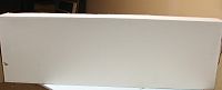
The next thing I did was take everything out and inspect it for damage. It was all perfect. I took lots of pics, but won’t bore you with all of them. Here are the highlights.
Wing
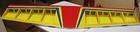
Obligatory close-up of spectacular dove tail joints.
Fuse, prior to removing extra covering around wing saddle and servo openings.

Control surfaces
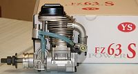
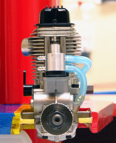
And finally, my two options for power. YS .63
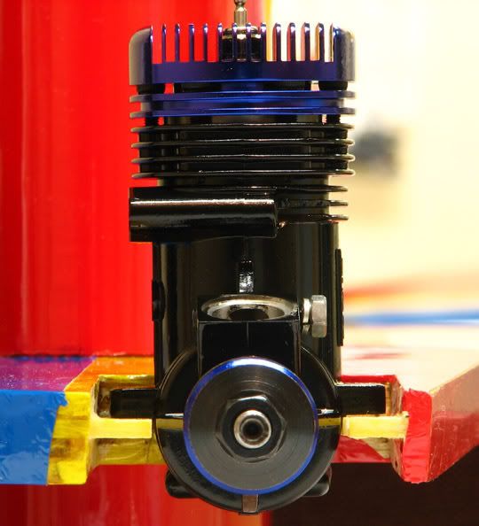
Or Just Engines J’EN .57
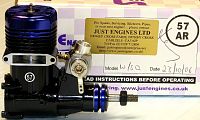
Both engines weigh within an ounce of each other. The YS is 17.6 with stock muffler and the JEN is 16.9 with the stock “super quiet” muffler. I’ve had some luck with mousse can pipes and could probably build one for the JEN and knock off another 1.5 to 2 ounces. I bought this engine recently on a whim (I gotta stop doing that!) and will probably put it in my old Fazer just to try it out. It has the same mounting dimensions as the OS .40 SF that is currently in the Fazer, so it should be a breeze to install it and see what it can do. According to the manufacturer, it will turn a 13 x 4 APC at 12,000, which sounds pretty good for a 17 ounce engine. Anyway, I’m pretty sure I’m going to use the YS in the Edge. I’ve never run a 4 stroke before, so it’s high time I give it a go.
I’m planning to use HS 6635s on elevator and rudder, HS 5245s on ailerons and HS 225 on throttle. I’ve read that this plane tends to come out nose heavy with a big 4 stroke on the nose and since I hate to add dead weight (I had to say that since everyone else seems to ), I chose beefier servos for the tail.
I’ve weighed all the components in the box, as well as all the radio and engine parts, and summarized it below. Unless I’ve missed something, it looks like the AUW will be around 4.5 pounds. I’m sure it will creep up a bit, as my planes always do, but if I can keep it under 4.75 pounds or so, I’ll be happy.
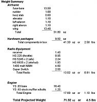
PS – Darn! I forgot to include the weight of prop and spinner. It’s already starting to creep up!
If you are curious enough to scroll down or perhaps even post a comment or suggestion, I’d be honored by your presence. I’d be especially interested to hear about any mods that I should definitely consider doing.I’ve been in and out of the hobby several times over the last 25 or 30 years, so I’m not a total rookie. However, things are changing and evolving so quickly that I’m certain there will always be more for me to learn. 3D is one of those things. Seeing what some of you folks can do with these crazy little beasts is simply astounding. This plane will hopefully serve me well as a 3D trainer and allow me to have as much fun as the rest of you.
OK, I’m not sure why, but everyone seems to post a picture of the box the plane came in, and who am I to go against the grain. Here is my box. Nice, isn’t it?
The next thing I did was take everything out and inspect it for damage. It was all perfect. I took lots of pics, but won’t bore you with all of them. Here are the highlights.
Wing
Obligatory close-up of spectacular dove tail joints.
Fuse, prior to removing extra covering around wing saddle and servo openings.
Control surfaces
And finally, my two options for power. YS .63
Or Just Engines J’EN .57
Both engines weigh within an ounce of each other. The YS is 17.6 with stock muffler and the JEN is 16.9 with the stock “super quiet” muffler. I’ve had some luck with mousse can pipes and could probably build one for the JEN and knock off another 1.5 to 2 ounces. I bought this engine recently on a whim (I gotta stop doing that!) and will probably put it in my old Fazer just to try it out. It has the same mounting dimensions as the OS .40 SF that is currently in the Fazer, so it should be a breeze to install it and see what it can do. According to the manufacturer, it will turn a 13 x 4 APC at 12,000, which sounds pretty good for a 17 ounce engine. Anyway, I’m pretty sure I’m going to use the YS in the Edge. I’ve never run a 4 stroke before, so it’s high time I give it a go.
I’m planning to use HS 6635s on elevator and rudder, HS 5245s on ailerons and HS 225 on throttle. I’ve read that this plane tends to come out nose heavy with a big 4 stroke on the nose and since I hate to add dead weight (I had to say that since everyone else seems to
), I chose beefier servos for the tail.I’ve weighed all the components in the box, as well as all the radio and engine parts, and summarized it below. Unless I’ve missed something, it looks like the AUW will be around 4.5 pounds. I’m sure it will creep up a bit, as my planes always do, but if I can keep it under 4.75 pounds or so, I’ll be happy.
PS – Darn! I forgot to include the weight of prop and spinner. It’s already starting to creep up!
 11-08-2006, 09:07 AM
#3
Senior Member
My Feedback: (97)
Join Date: Nov 2003
Location: Billings,
MO
Posts: 921
Likes: 0
Received 0 Likes
on
0 Posts
Go with the YS for power and stick it all the way to the back of the rail. You don't have to use those servos as standards are just fine and would actually save weight. You will probably still have to add some lead in the tail or find a spot aft of the wing for your battery. It will be nose heavy. A good mod. is to use a sulivan tail wheel. The stock one is OK but after a couple good smacks it's time for repair.
11-08-2006, 05:10 PM
#4
Senior Member
My Feedback: (2)
Join Date: Dec 2004
Location: Raritan,
NJ
Posts: 126
Likes: 0
Received 0 Likes
on
0 Posts
Got another question.
If the motor is cocked in a upwards position say 1/4 inch will the plane on low throttle climb?
If the motor is cocked in a upwards position say 1/4 inch will the plane on low throttle climb?
11-08-2006, 10:47 PM
#5
Senior Member
Thread Starter
Join Date: Jul 2006
Location: Charlottesville,
VA
Posts: 723
Likes: 0
Received 0 Likes
on
0 Posts
Phil, as soon as I get some time on the J’EN, I’ll post up some sort of mini-review. I have read about transition issues, but I’m hoping that with enough tinkering, it can be made to behave.
Iowa, will do regarding the location on the mounting rail. I’ll get it as rearward as I can. I picked up a Sullivan tail wheel today, but have decided on a different course of action. Instead of a steerable tail wheel, I’m going to try just a music wire skid. That huge rudder should have no problem turning the plane and if I’m not happy with it, I can always install the Sullivan unit. My old Fazer lost it’s tailwheel and I flew it for several seasons with just a skid, so hopefully it won’t be a problem.
Mcoccia, I’m afraid I can’t offer much guidance on thrust issues. I plan to mount the engine as designed and go from there.
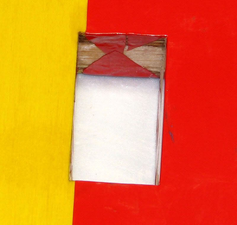
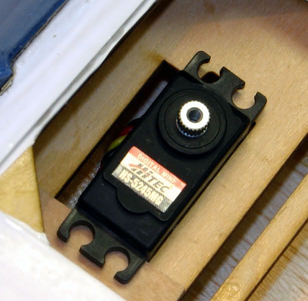
My first task is to open up all the servo bays on the fuse, remove the covering from the wing saddle, and clear out the slot where the horizontal stab is installed. For all three servo slots, I cut an X pattern in the covering and ironed the flaps down into the fuse. I have this obsession about clean, neat covering seams and this is something that helps keep them from working loose. It also helps to prevent fuel seepage. However, I wasn’t satisfied this would be enough, so I mixed up a batch of 30 minute epoxy and carefully smeared a very thin layer of it over all the exposed wood in the three servo slots on the fuse. This should allow the plane to last long enough for me to destroy it before it gets fuel soaked. Here are a couple pics of the throttle servo slot.
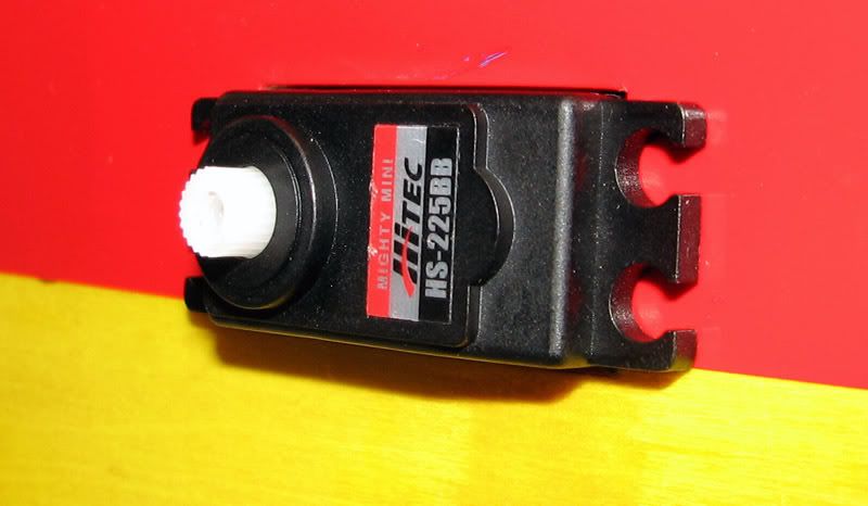
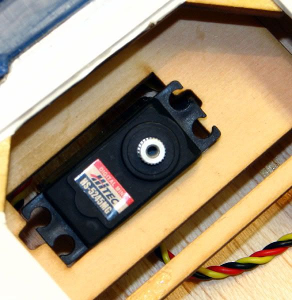
Since I was working on the servo slots, I wanted to make sure the servos would fit before sealing them up with epoxy. While trying to get the throttle servo in place (it’s an HS225), I realized that the strain relief grommet was preventing the servo from passing through the slot. I tried wiggling and twisting it, but nothing I did enabled the servo to slide into place.
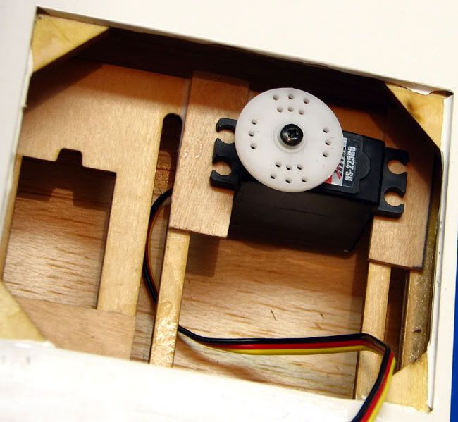
I was just about to drag out the Dremel and grind a slot in the fuse for clearance when a thought occurred to me. (What? It happens! )Why not take the top off the servo case, pass the bottom of the servo through the left side of the fuse and the top of the case through the right side of the fuse? I should then be able to reassemble the servo without having to grind a notch in the servo cutout. Now, this may be old news to some of you, but to me it was like a moment of inspiration. I had never thought of doing this before.
First I carefully took the servo apart, making sure to snap a couple of pics of how the gear train went together…..just in case.
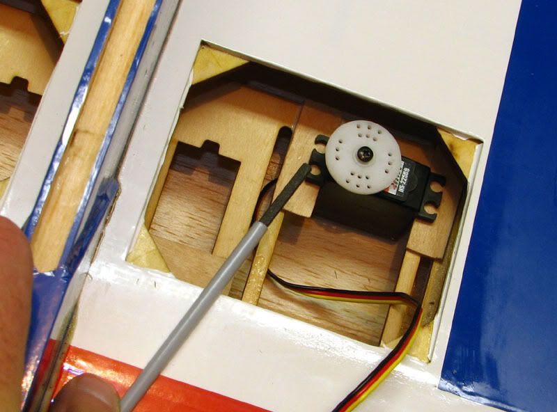
Then, I slid it in the servo hole from the left side of the fuse.
The top of the case went in from the right side…..
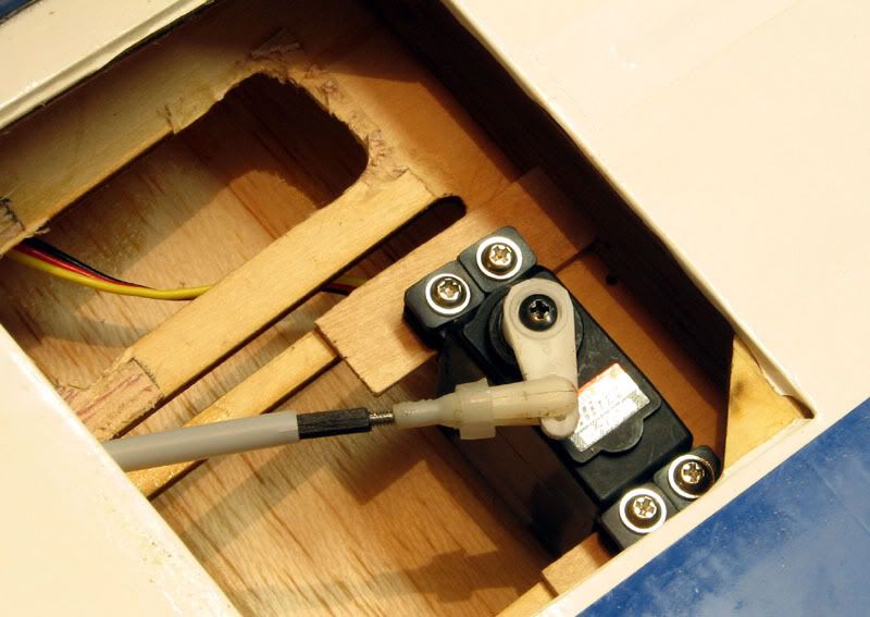
And then the 4 screws on the bottom were tightened.
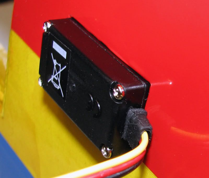
I was overjoyed to see that it actually worked the way I had hoped. To make sure I hadn’t put the servo together wrong, I hooked it up to the receiver and a battery pack and it worked fine. Will wonders never cease?
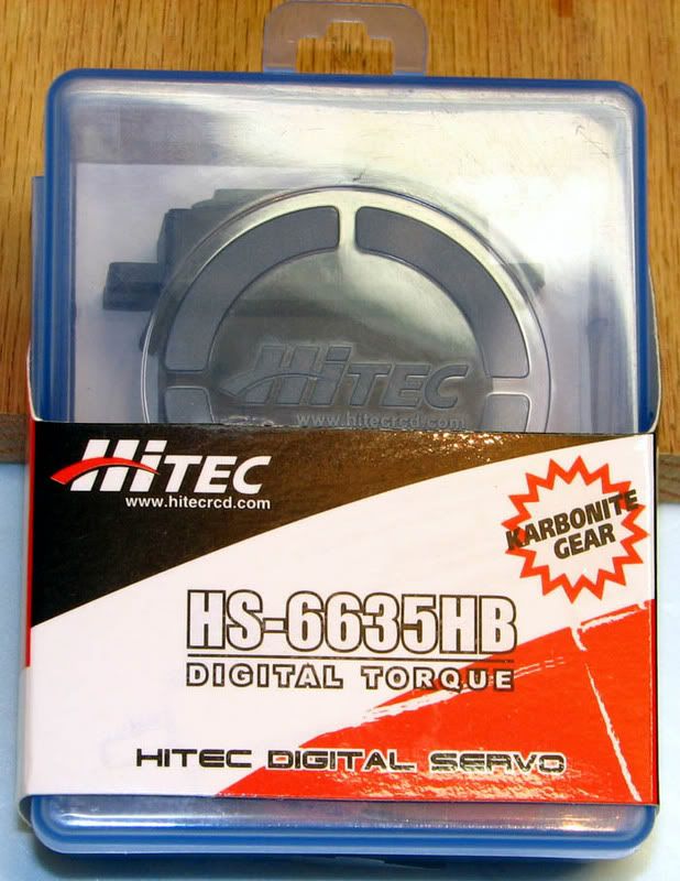
While I was test fitting the servos, I took a couple of pictures of one of the HS6635s. It was packaged in a very sturdy plastic box with a nice assortment of arms. While I’m sure they would be more than adequate for this plane, I had already purchased the Dubro arms recommended by Extreme Flight. Anyway, here is the servo in the packaging. I’ve always bought low end servos so it was nice to see the extra attention to detail Hitec puts into it’s middle tier product offerings.
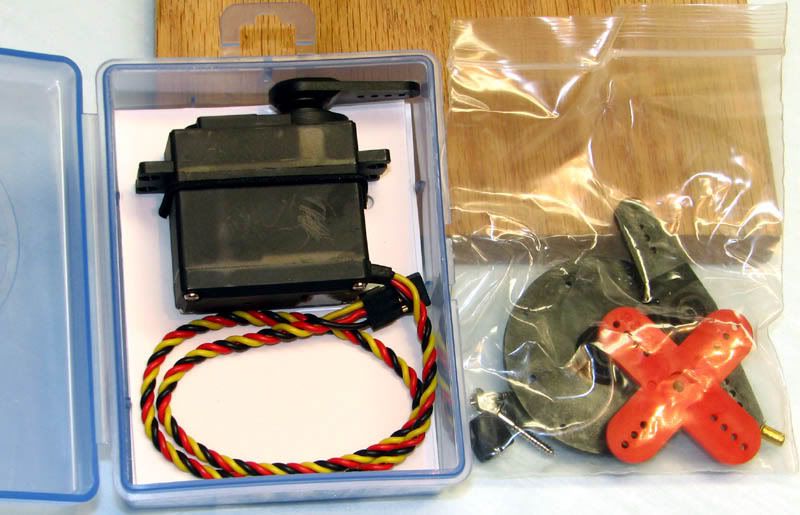
Here it is with all them arms and mounting hardware.
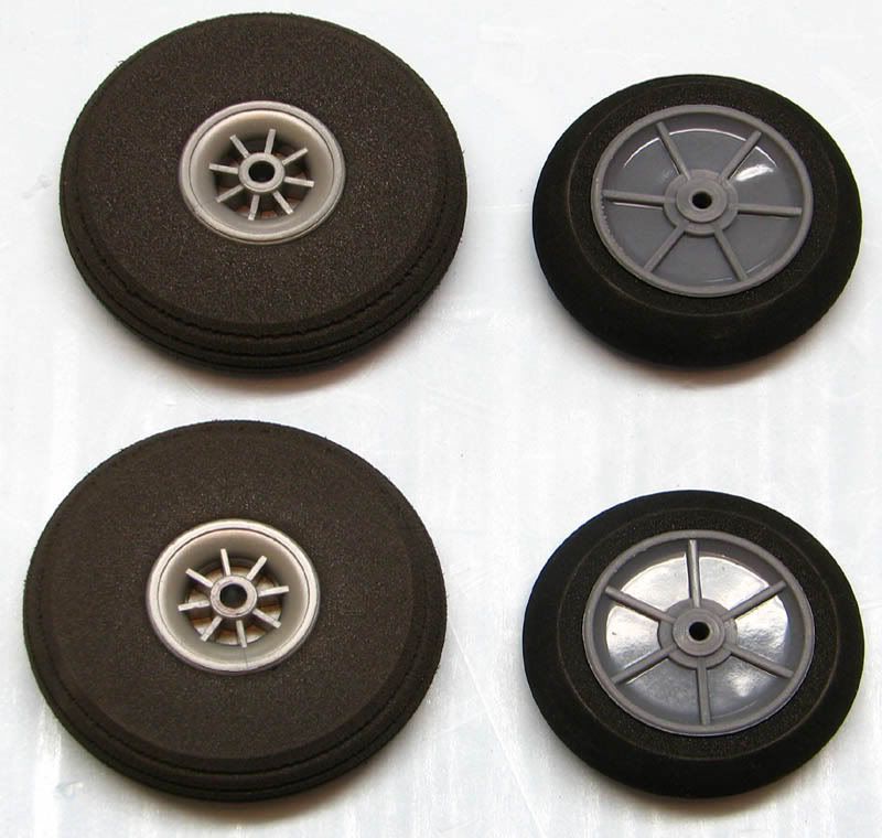
OK, back to the Edge. The next step in the manual after opening up the servo holes is to assemble and mount the main gear. The included wheels are 2 inches in diameter and in my experience, the grass at our field is just a bit too long for them. I have some 2.5 inch Dubro light weight wheels that I will substitute for the stock ones. The stock ones weigh a total of 14 grams, whereas the Dubros weigh 20 grams. Hopefully those 6 grams won’t kill me. Here are the new ones compared to stock.
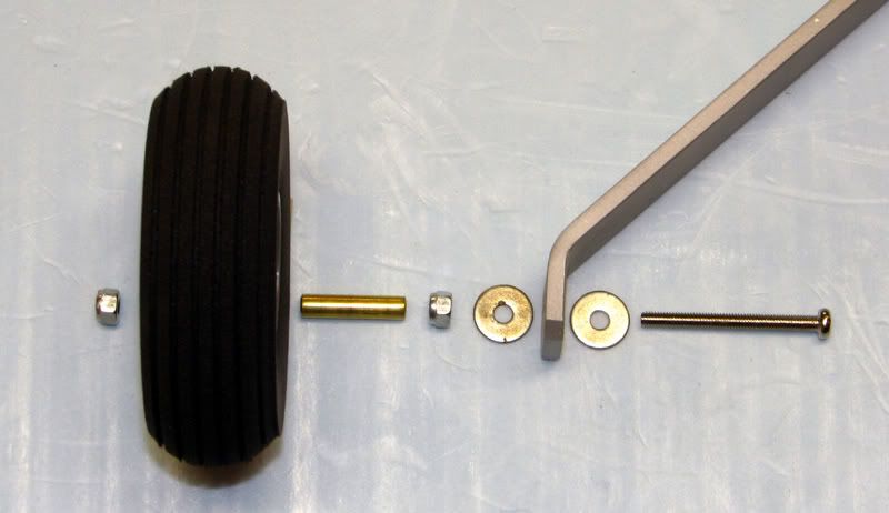
The assembly is pretty straight forward (a bolt, 2 washers and 2 nuts), but I couldn’t leave it alone. I cut some brass (or is it copper??) tubing to slip over the provided wheel axle bolts. This prevents the threads from chewing away the hub of the wheel and getting all wobbly.
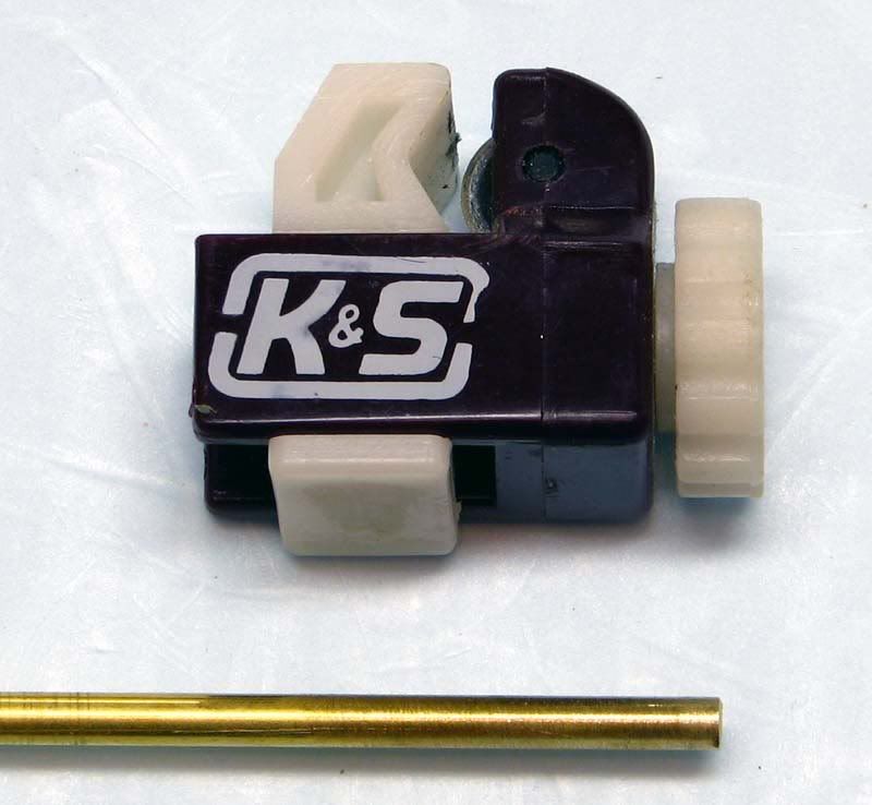
To get a clean edge on the tubing, I used a K&S tubing cutter. I used to use a razor saw, but no matter how careful I was, I always ended up with burrs and sharp edges. The tubing cutter makes it much easier and less time consuming.
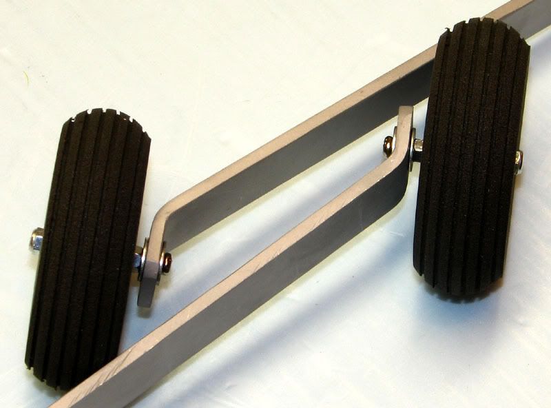
Here are the finished gear assemblies.
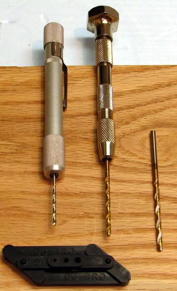
The gear legs are used as a pattern to locate the mounting holes on the fuse. After drilling pilot holes with a 1/16” bit, I drilled the final hole with a 9/64” bit and sealed the covering by poking a hot soldering iron into each hole.
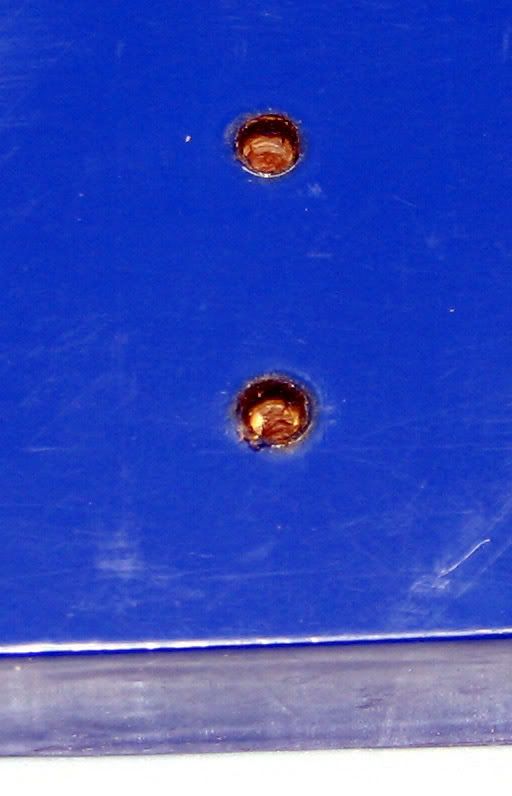
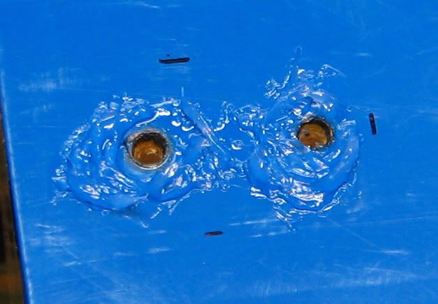
I then trial fit the gear to the fuse and made a small reference mark on each of the three sides. You can see one of these in this pic.
This pic shows all three after the gear was removed.
My plan here is to seal this area and prevent fuel from seeping into the bolt holes over time. To do that, I used some blue silicone sealant.
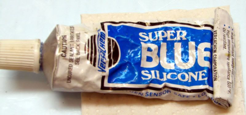
I smeared a little dab of it on a paper towel.
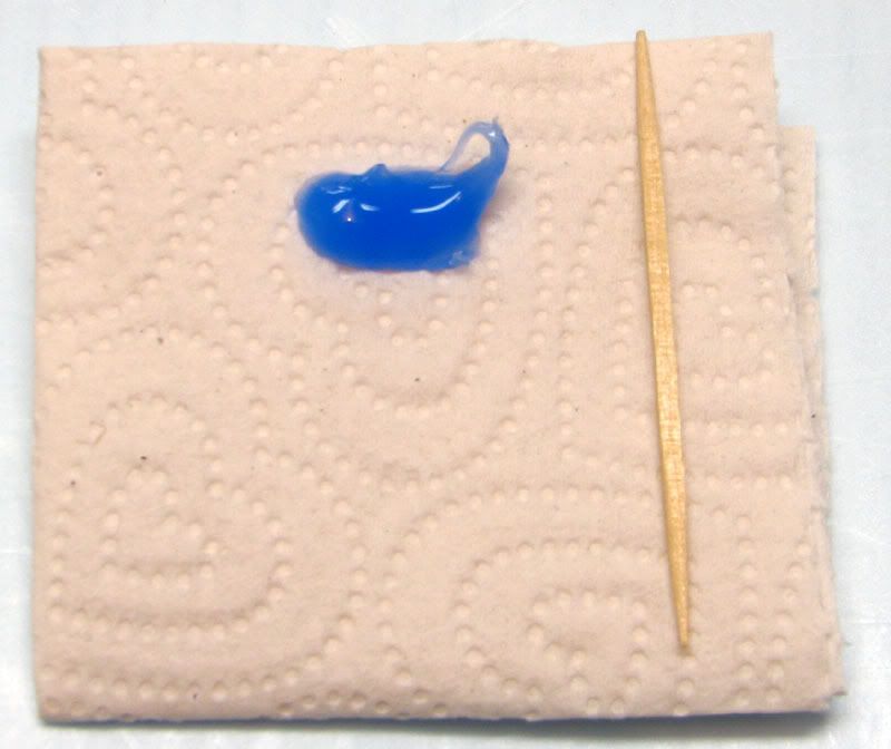
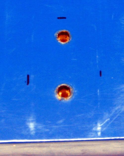
And used a toothpick to smear it around each of the bolt holes on the fuse. I was careful not to get any in the holes, but it probably wouldn’t have hurt anything.
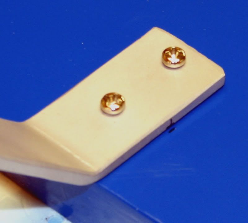
I then assembled both sides of the gear with the supplied bolts, but did not tighten them down completely. The goal is to leave a thin film of sealant between the gear and fuse, not to squeeze it all out. After the sealant has fully cured, I will securely tighten the bolts and should have a very fuel proof assembly.
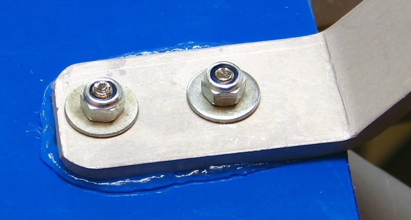
Before the sealant gets to tacky, it’s easy to clean up the excess with a little denatured alcohol on a paper towel. The end result looks nice and neat.
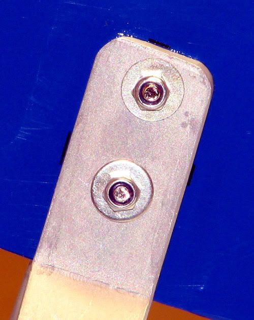
Here is a side view of the completed gear.
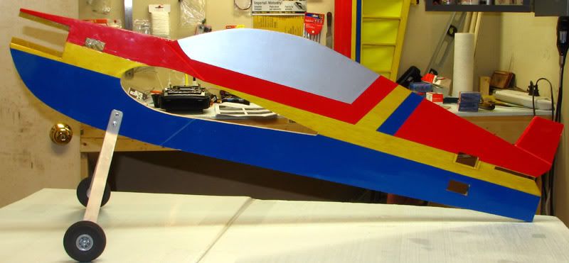
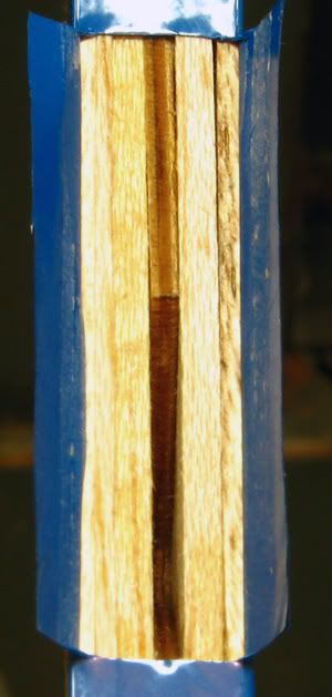
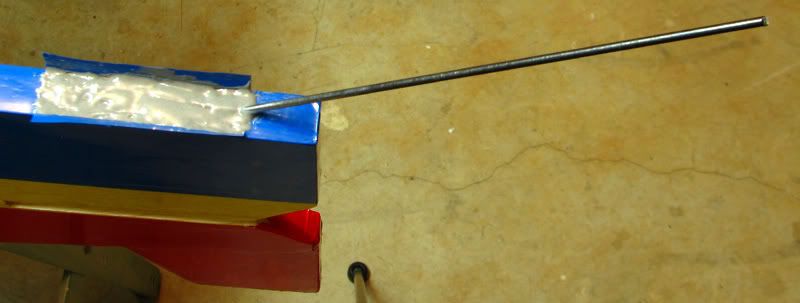
The next step is to install the tail wheel. As I noted above, I’m going to try just using a tail skid for now and see how the plane responds on the ground. Here is a pic of the underside of the fuse all opened up and ready for gluing in the skid.
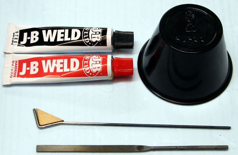
I considered using either regular 30 minute epoxy or Gorilla glue for this step, but eventually settled on JB weld. My reasoning is that since I’m trying to glue metal to wood, it would probably be best to use an epoxy designed to work with metal. Here is what I used for this step. JB Weld, a small inverted food service cup as a platform to mix the JB Weld and a file to rough up the skid and remove all the black paint on it. Not shown is some denatured alcohol for thoroughly cleaning all traces of oil and dirt off the skid.
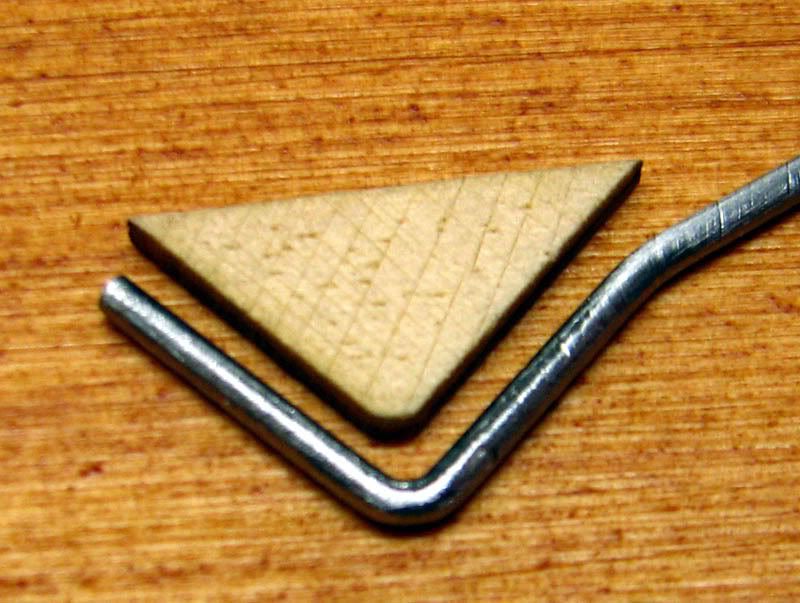
I took extra care to thoroughly roughen the skid in hopes that the JB Weld would be able to get a good grip. I also used a hobby knife to score and stab the triangle plywood wedge to help ensure good glue penetration.
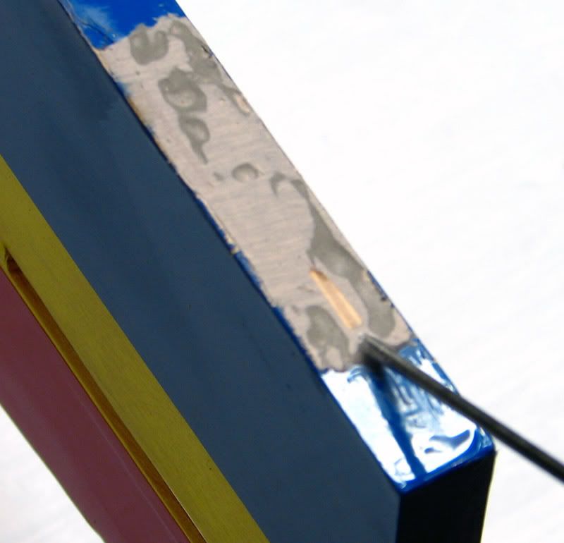
Finally, the glue was mixed, the slot in the fuse was thoroughly filled, the skid and wedge was coated, and the whole mess assembled. After a bit of clean up, it looks like a pretty secure, and hopefully long lasting setup. When the JB Weld is fully cured, I’ll smooth it out a bit with the Dremel and reseal the covering over the wound.
That’s all I have time for tonight, but hope to get more done tomorrow night. Thanks for tuning in!
Iowa, will do regarding the location on the mounting rail. I’ll get it as rearward as I can. I picked up a Sullivan tail wheel today, but have decided on a different course of action. Instead of a steerable tail wheel, I’m going to try just a music wire skid. That huge rudder should have no problem turning the plane and if I’m not happy with it, I can always install the Sullivan unit. My old Fazer lost it’s tailwheel and I flew it for several seasons with just a skid, so hopefully it won’t be a problem.
Mcoccia, I’m afraid I can’t offer much guidance on thrust issues. I plan to mount the engine as designed and go from there.
My first task is to open up all the servo bays on the fuse, remove the covering from the wing saddle, and clear out the slot where the horizontal stab is installed. For all three servo slots, I cut an X pattern in the covering and ironed the flaps down into the fuse. I have this obsession about clean, neat covering seams and this is something that helps keep them from working loose. It also helps to prevent fuel seepage. However, I wasn’t satisfied this would be enough, so I mixed up a batch of 30 minute epoxy and carefully smeared a very thin layer of it over all the exposed wood in the three servo slots on the fuse. This should allow the plane to last long enough for me to destroy it before it gets fuel soaked.
Here are a couple pics of the throttle servo slot.Since I was working on the servo slots, I wanted to make sure the servos would fit before sealing them up with epoxy. While trying to get the throttle servo in place (it’s an HS225), I realized that the strain relief grommet was preventing the servo from passing through the slot. I tried wiggling and twisting it, but nothing I did enabled the servo to slide into place.
I was just about to drag out the Dremel and grind a slot in the fuse for clearance when a thought occurred to me. (What? It happens!
)Why not take the top off the servo case, pass the bottom of the servo through the left side of the fuse and the top of the case through the right side of the fuse? I should then be able to reassemble the servo without having to grind a notch in the servo cutout. Now, this may be old news to some of you, but to me it was like a moment of inspiration. I had never thought of doing this before. First I carefully took the servo apart, making sure to snap a couple of pics of how the gear train went together…..just in case.
Then, I slid it in the servo hole from the left side of the fuse.
The top of the case went in from the right side…..
And then the 4 screws on the bottom were tightened.
I was overjoyed to see that it actually worked the way I had hoped. To make sure I hadn’t put the servo together wrong, I hooked it up to the receiver and a battery pack and it worked fine. Will wonders never cease?
While I was test fitting the servos, I took a couple of pictures of one of the HS6635s. It was packaged in a very sturdy plastic box with a nice assortment of arms. While I’m sure they would be more than adequate for this plane, I had already purchased the Dubro arms recommended by Extreme Flight. Anyway, here is the servo in the packaging. I’ve always bought low end servos so it was nice to see the extra attention to detail Hitec puts into it’s middle tier product offerings.
Here it is with all them arms and mounting hardware.
OK, back to the Edge. The next step in the manual after opening up the servo holes is to assemble and mount the main gear. The included wheels are 2 inches in diameter and in my experience, the grass at our field is just a bit too long for them. I have some 2.5 inch Dubro light weight wheels that I will substitute for the stock ones. The stock ones weigh a total of 14 grams, whereas the Dubros weigh 20 grams. Hopefully those 6 grams won’t kill me.
Here are the new ones compared to stock.The assembly is pretty straight forward (a bolt, 2 washers and 2 nuts), but I couldn’t leave it alone.
I cut some brass (or is it copper??) tubing to slip over the provided wheel axle bolts. This prevents the threads from chewing away the hub of the wheel and getting all wobbly.To get a clean edge on the tubing, I used a K&S tubing cutter. I used to use a razor saw, but no matter how careful I was, I always ended up with burrs and sharp edges. The tubing cutter makes it much easier and less time consuming.
Here are the finished gear assemblies.
The gear legs are used as a pattern to locate the mounting holes on the fuse. After drilling pilot holes with a 1/16” bit, I drilled the final hole with a 9/64” bit and sealed the covering by poking a hot soldering iron into each hole.
I then trial fit the gear to the fuse and made a small reference mark on each of the three sides. You can see one of these in this pic.
This pic shows all three after the gear was removed.
My plan here is to seal this area and prevent fuel from seeping into the bolt holes over time. To do that, I used some blue silicone sealant.
I smeared a little dab of it on a paper towel.
And used a toothpick to smear it around each of the bolt holes on the fuse. I was careful not to get any in the holes, but it probably wouldn’t have hurt anything.
I then assembled both sides of the gear with the supplied bolts, but did not tighten them down completely. The goal is to leave a thin film of sealant between the gear and fuse, not to squeeze it all out. After the sealant has fully cured, I will securely tighten the bolts and should have a very fuel proof assembly.
Before the sealant gets to tacky, it’s easy to clean up the excess with a little denatured alcohol on a paper towel. The end result looks nice and neat.
Here is a side view of the completed gear.
The next step is to install the tail wheel. As I noted above, I’m going to try just using a tail skid for now and see how the plane responds on the ground. Here is a pic of the underside of the fuse all opened up and ready for gluing in the skid.
I considered using either regular 30 minute epoxy or Gorilla glue for this step, but eventually settled on JB weld. My reasoning is that since I’m trying to glue metal to wood, it would probably be best to use an epoxy designed to work with metal. Here is what I used for this step. JB Weld, a small inverted food service cup as a platform to mix the JB Weld and a file to rough up the skid and remove all the black paint on it. Not shown is some denatured alcohol for thoroughly cleaning all traces of oil and dirt off the skid.
I took extra care to thoroughly roughen the skid in hopes that the JB Weld would be able to get a good grip. I also used a hobby knife to score and stab the triangle plywood wedge to help ensure good glue penetration.
Finally, the glue was mixed, the slot in the fuse was thoroughly filled, the skid and wedge was coated, and the whole mess assembled. After a bit of clean up, it looks like a pretty secure, and hopefully long lasting setup. When the JB Weld is fully cured, I’ll smooth it out a bit with the Dremel and reseal the covering over the wound.
That’s all I have time for tonight, but hope to get more done tomorrow night. Thanks for tuning in!
11-09-2006, 10:55 PM
#6
Senior Member
Thread Starter
Join Date: Jul 2006
Location: Charlottesville,
VA
Posts: 723
Likes: 0
Received 0 Likes
on
0 Posts
The tasks for tonight include finishing up the tail skid installation, gluing in the horizontal stab and pre-hinging the elevator. The JB Weld cured as hard as a rock and after a few minutes with a sanding block, I was satisfied enough to cover the area with a scrap of covering.
I slipped a scrap from the wing saddle area over the tail skid and trimmed it to approximately the right size.
After a few minutes with the covering iron, the job was done.
To install the horizontal stab, I first found the center point on the trailing edge and extended a chord wise line from there to the leading edge.

The fuse is ½” wide at the tail so I marked and drew two more lines, each one ¼” away from the centerline.
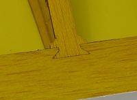
I used a soldering iron to remove the covering between the lines and then repeated this procedure on the other side of the stab. This left a ½” wide bare strip around the exact center of the stabilizer. It was now time to trial fit the stab into the slot in the fuse. This was my first big disappointment so far with this ARF. This pic speaks for itself.
Closer examination of the slot in the fuse revealed the problem. It was clearly not cut properly and the stab was very loose and floppy.
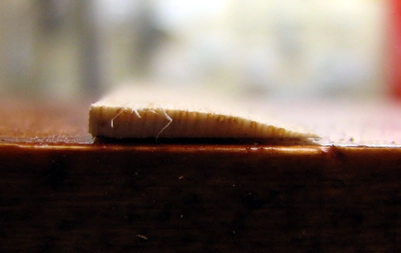
I could have just filled the gaps with epoxy and taped or pinned the stab at the correct angle, but instead I decided to make a balsa wedge to insert into the slot and hopefully get everything to line up properly. I started with a ½: wide strip of 1/16” balsa about 3 inches long. My intent was to make a tapered wedge , but what I ended up with looked more like a curved radius. I decided to give it a shot regardless.
With just a little fiddling, it actually did what I hoped it would do!
I was just about to mix up the epoxy and glue the stab in place when it occurred to me that it would be much easier to prep the stab with hinges before attaching it to the fuse. I tracked down my Dubro hinge slotting kit, drill bits, pin vices and some old Goldberg (I think) hinges.
I’m pretty sure these aren’t made anymore and I’m sad to be using the last of my supply. I’m sure the CA hinges in the kit are fine, and I don’t have anything against them in general, I just prefer my old Goldberg hinges. Here is a pic of one of the hinges installed in the stab and one sitting next to a scrap piece of balsa. These little suckers really grip the wood and are hard to pull out after test fitting, even without glue.
After getting the hinges all ready to glue, it was time to glue in the stab. The wedge worked as planned and I’m pleased with how the tail is coming together.
Tomorrow I think it’s time to pre-hinge the ailerons and trial fit the wing. This thing is finally starting to look like an airplane!
I slipped a scrap from the wing saddle area over the tail skid and trimmed it to approximately the right size.
After a few minutes with the covering iron, the job was done.
To install the horizontal stab, I first found the center point on the trailing edge and extended a chord wise line from there to the leading edge.
The fuse is ½” wide at the tail so I marked and drew two more lines, each one ¼” away from the centerline.
I used a soldering iron to remove the covering between the lines and then repeated this procedure on the other side of the stab. This left a ½” wide bare strip around the exact center of the stabilizer. It was now time to trial fit the stab into the slot in the fuse. This was my first big disappointment so far with this ARF. This pic speaks for itself.
Closer examination of the slot in the fuse revealed the problem. It was clearly not cut properly and the stab was very loose and floppy.
I could have just filled the gaps with epoxy and taped or pinned the stab at the correct angle, but instead I decided to make a balsa wedge to insert into the slot and hopefully get everything to line up properly. I started with a ½: wide strip of 1/16” balsa about 3 inches long. My intent was to make a tapered wedge , but what I ended up with looked more like a curved radius. I decided to give it a shot regardless.
With just a little fiddling, it actually did what I hoped it would do!
I was just about to mix up the epoxy and glue the stab in place when it occurred to me that it would be much easier to prep the stab with hinges before attaching it to the fuse. I tracked down my Dubro hinge slotting kit, drill bits, pin vices and some old Goldberg (I think) hinges.
I’m pretty sure these aren’t made anymore and I’m sad to be using the last of my supply. I’m sure the CA hinges in the kit are fine, and I don’t have anything against them in general, I just prefer my old Goldberg hinges. Here is a pic of one of the hinges installed in the stab and one sitting next to a scrap piece of balsa. These little suckers really grip the wood and are hard to pull out after test fitting, even without glue.
After getting the hinges all ready to glue, it was time to glue in the stab. The wedge worked as planned and I’m pleased with how the tail is coming together.
Tomorrow I think it’s time to pre-hinge the ailerons and trial fit the wing. This thing is finally starting to look like an airplane!
11-10-2006, 03:56 PM
#7

My Feedback: (6)
Join Date: Dec 2001
Location: Georgetown,
IN
Posts: 1,515
Likes: 0
Received 0 Likes
on
0 Posts
I have had two of these now and one still in reserve. I would follow the directions and keep the nose as light as possible. The one thing all these planes have in common is they come out noseheavy. The problem can be solved by tail mounting the battery. I see you are doing several things of your own choice. I really recommend just follow the directions. Those Goldberg hinges are sturdy but they are stiff and put undo strain on your servo. I have no knowledge of the .57 two stroke you show but I fly mine on a YS63 and love it.
I think a build thread on this plane is fine as one has not been done for a bit now. I did one here about two years ago if memory serves.
Jeff Williams
I think a build thread on this plane is fine as one has not been done for a bit now. I did one here about two years ago if memory serves.
Jeff Williams

 11-10-2006, 04:32 PM
#9
Senior Member
My Feedback: (51)

Join Date: Jul 2002
Location: Ashland, KY
Posts: 5,833
Likes: 0
Received 0 Likes
on
0 Posts
Most excellent build and skills... thanks for sharing... Nearly brilliant idea for getting the servo in the tight spaces... woulda never occured to me... consider that an idea "borrowed" permanently.
11-12-2006, 07:22 PM
#10
Senior Member
Thread Starter
Join Date: Jul 2006
Location: Charlottesville,
VA
Posts: 723
Likes: 0
Received 0 Likes
on
0 Posts
Jeff, thanks for the tips. I probably won’t choose to mount the battery on the fuse, however I haven’t gotten to that point yet, so it’s still up in the air. I don’t doubt you for an instant about being nose heavy, but I’ll “weigh” my options when the time comes. Until then, I’ll do everything I can to keep the nose light. And I will take your guidance about not deviating from the instructions very seriously. So far, I don’t think I’ve stepped too far out of line. My Sullivan tail wheel assembly can still easily be installed and the hinges aren’t glued in yet, which is a good thing because I’m considering trying out the Robart hinge points with which so many people have reported success. They have a metal hinge pin and the barbs should grip the wood at least as good as the Goldberg ones do. This allows me to use my existing holes AND get around the potential stiffness issue you mentioned. If you don’t mid me asking, what prop do you run on your YS? I’ve got a 13x4W, a 14x4W and I already had an old, unused Zinger 14x4 wood prop lying around, so I’ll be giving those a try.
Rob, thanks for the kind words. I appreciate you taking the time to comment.
Maudib, brilliant is my middle name. Actually, it’s Joseph, but since you’re not asking for ID, maybe I’ll be able to get away with it. The sad part is that I probably won’t have another good idea the rest of the year. And for what it’s worth, I’m a big fan of yours. I’ve seen you go out of your way countless times to explain techniques and theory to those of us with less experience than you. Your generosity speaks volumes and, on behalf of all those you have helped, THANKS!
The next thing I did was pre-hinge the ailerons, and get the wing glued in. I drilled, slotted and test fit the ailerons just like the elevator, so that was nothing more than a bit tedious and not worthy of further comment. In the process, however, I came across my second disappointment with this bird. The leading edge of the left aileron is far, FAR from straight. If I hold one end against a straightedge, the other end is over 3/16” away from the same straightedge.
This is not a huge deal and since I planned to seal the hinge line anyway, it shouldn’t make a difference in the flying characteristics….it will just look bad, even if I’m the only one who notices it. I can live with that, but it would have been nice to have a straight leading edge.
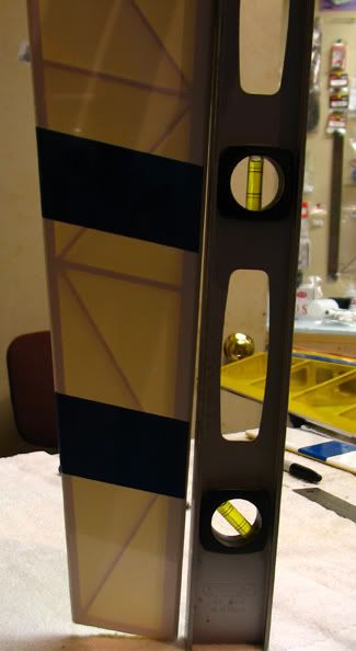
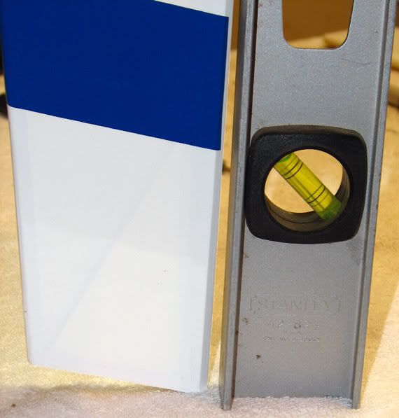
For the wing, I first slid it in and measured from the trailing edge of the wing tips to the leading edge of the stab to ensure it was centered and straight. I made a few marks along the fuse/wing joint and removed the wing.
I then used a ruler to connect the marks and outline the covering to be removed.
After firing up the soldering iron, I used it to burn through the covering just inside the lines.
The strip of covering came off pretty cleanly and prevented any damage to the wood underneath.
After using a small sanding block to remove some of the char, the wing was reinserted and epoxied into place. The alignment may not be perfect, but my 40-something eyes can’t see any problems, so I’m happy.
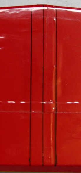
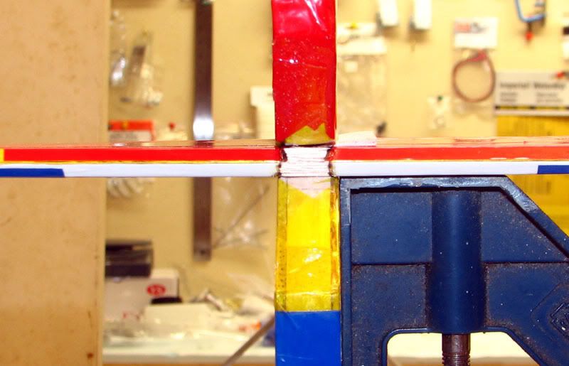
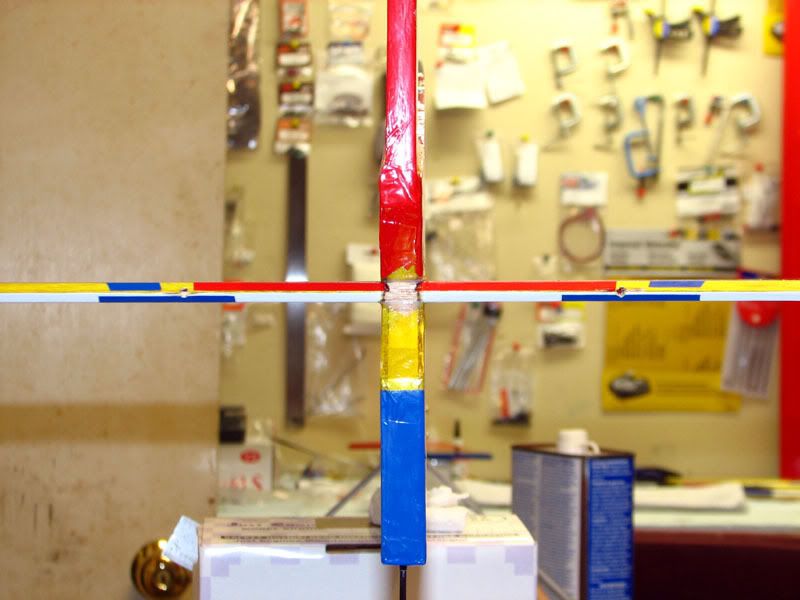
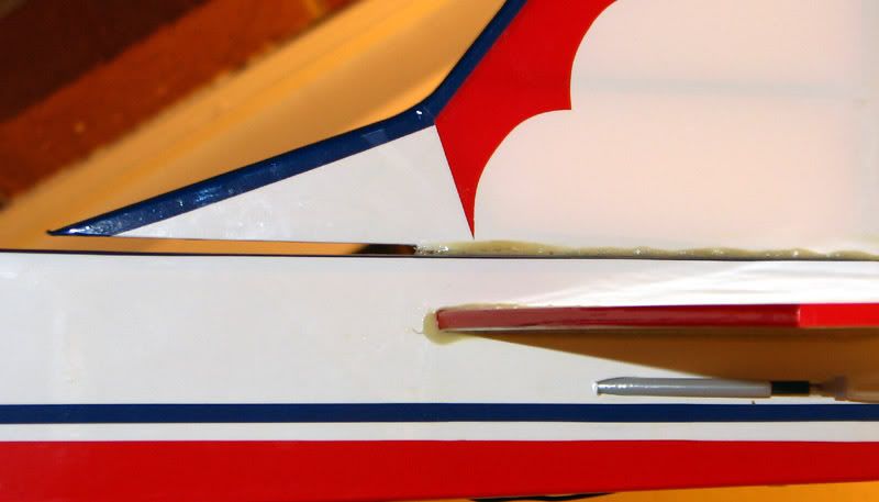
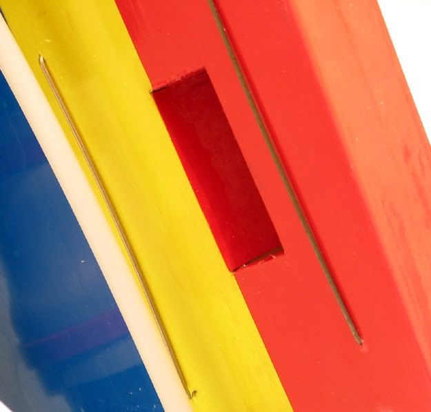
The amount of right thrust built into the phenolic engine mounting rails is clearly visible in this picture.
Although my eyes can’t detect it, I wouldn’t be surprised if there is a bit of down thrust built in as well. The attention to detail in this ARF is quite impressive. While it’s not perfect, it really is leaps and bounds ahead of what was commonly available just a few short years ago.
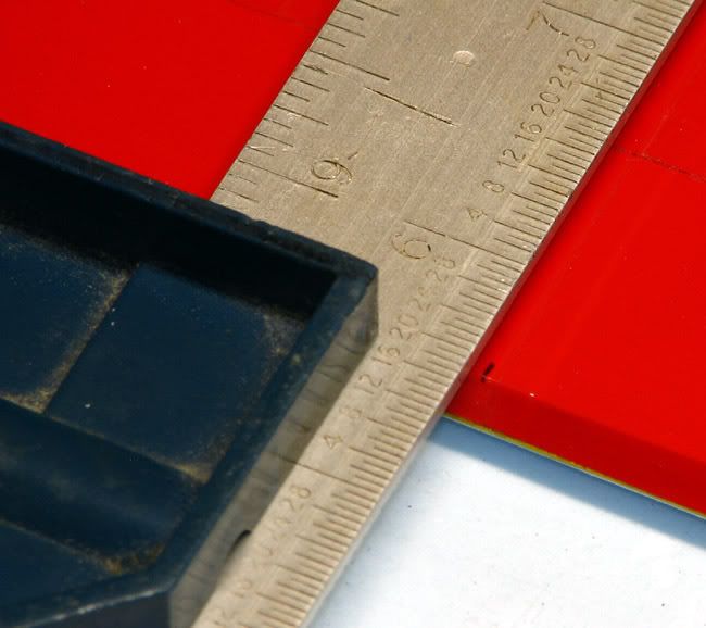
Just before I glued the wing, it occurred to me that it would be easier to test fit the engine without the wing in place. The YS crankcase is right at 36 mm wide and the rails were just about 35 mm apart, so it just took a few swipes of 100 grit to open them up enough for a glove-like fit.
As an added bonus, the JEN also fits this same opening, so if I want to experiment with it in this plane at some point, it should be a piece of cake to drop it in.
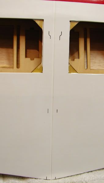
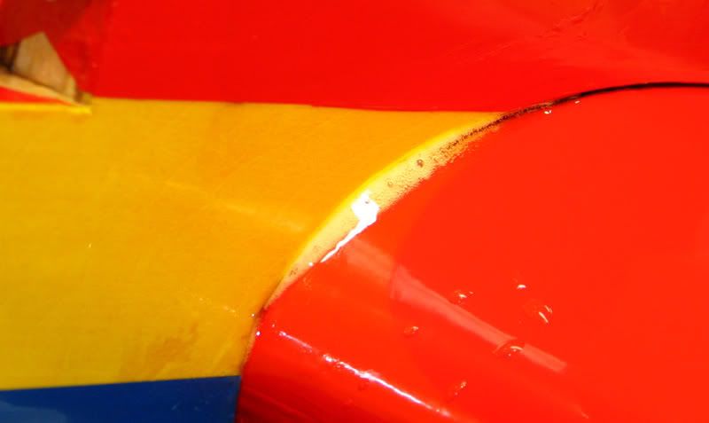
After the epoxy on the wing cured, I was inspecting the joint and double checking all the measurements when I spotted this.

And this.
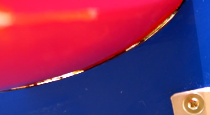
In case it’s not obvious, that’s light you see coming through the gap between the wing and fuse! I think this is probably typical of profile ships, at least it was on all three Fazers I’ve built over the years. While I would have preferred to see a better fit, I don’t think this is a big deal. To address it, I assembled the necessary supplies.
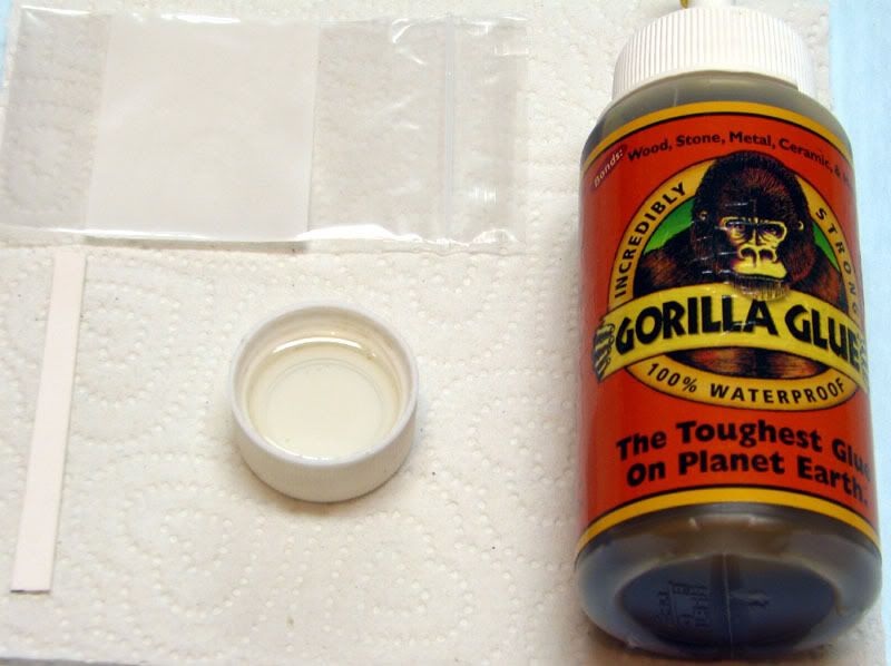
I considered using a mixture of epoxy and micro balloons, but was not confident I could get all the gaps filled AND keep them filled while it cured. Gorilla Glue is prized for its foaming action and tremendous strength, so I figured this was the perfect place to use it. Had I inspected the joint more closely before gluing it, I probably would have just used GG the first time around. Live and learn, eh?
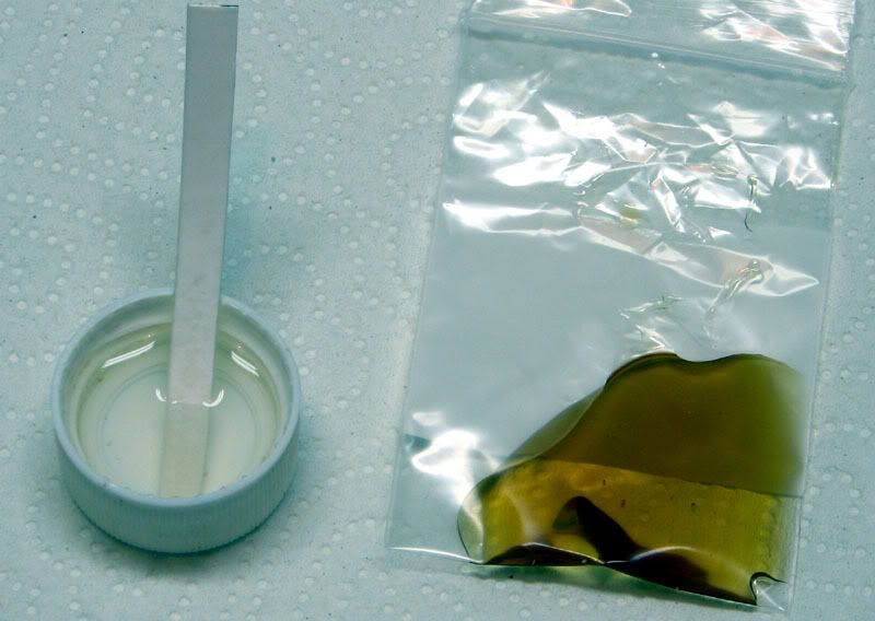
Anyway, I soaked a strip of index card in plain water and then ran it inside the gap several times to get the area moist. Then I put a tablespoon or so of GG into the small ziplock bag and snipped off one corner. I use the resulting “pastry bag” to squirt the GG into the gap. The flat bag was very easy to insert deep into the gap. I just slowly pulled it out as the GG went in. I repeated this on all 4 sides of the joint and cleaned of the excess. I returned every few minutes to wipe away the excess glue as it oozed out of the gap.
Anyone who has ever used this stuff, knows that you can’t just walk away after you get the glue in the joint. The very first time I ever used GG I learned this lesson the hard way.
What you’re looking at is a vertical stab that lifted itself out of it’s slot after I installed it with GG and walked away for the night. Fortunately for me, the plane still flew well and the joint has held up fine.
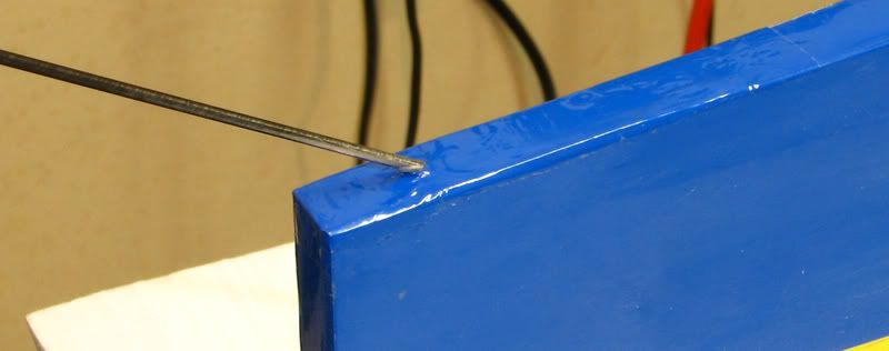
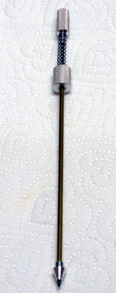
The last thing I managed to do was get the tail servos mounted. These went in without any hacking (or disassembly!) required. I used my Great Planes Dead Center thingy to drill the holes.
Then, like everyone else on the planet seems to do, I hardened the holes with CA and screwed the servos into place. That’s where I stand as of now. Next up is to install the aileron servos, get all the hinges glued and start working on control linkages.
Thanks again to all those who have posted comments and suggestions. Please keep them coming. If left to my own devices, this Edge may end up with a smoke system, auto pilot, parachute drop and sailplane tow hook.
Until then, I’ll do everything I can to keep the nose light. And I will take your guidance about not deviating from the instructions very seriously. So far, I don’t think I’ve stepped too far out of line. My Sullivan tail wheel assembly can still easily be installed and the hinges aren’t glued in yet, which is a good thing because I’m considering trying out the Robart hinge points with which so many people have reported success. They have a metal hinge pin and the barbs should grip the wood at least as good as the Goldberg ones do. This allows me to use my existing holes AND get around the potential stiffness issue you mentioned. If you don’t mid me asking, what prop do you run on your YS? I’ve got a 13x4W, a 14x4W and I already had an old, unused Zinger 14x4 wood prop lying around, so I’ll be giving those a try. Rob, thanks for the kind words. I appreciate you taking the time to comment.
Maudib, brilliant is my middle name. Actually, it’s Joseph, but since you’re not asking for ID, maybe I’ll be able to get away with it.
The sad part is that I probably won’t have another good idea the rest of the year. And for what it’s worth, I’m a big fan of yours. I’ve seen you go out of your way countless times to explain techniques and theory to those of us with less experience than you. Your generosity speaks volumes and, on behalf of all those you have helped, THANKS! The next thing I did was pre-hinge the ailerons, and get the wing glued in. I drilled, slotted and test fit the ailerons just like the elevator, so that was nothing more than a bit tedious and not worthy of further comment. In the process, however, I came across my second disappointment with this bird. The leading edge of the left aileron is far, FAR from straight. If I hold one end against a straightedge, the other end is over 3/16” away from the same straightedge.
This is not a huge deal and since I planned to seal the hinge line anyway, it shouldn’t make a difference in the flying characteristics….it will just look bad, even if I’m the only one who notices it. I can live with that, but it would have been nice to have a straight leading edge.
For the wing, I first slid it in and measured from the trailing edge of the wing tips to the leading edge of the stab to ensure it was centered and straight. I made a few marks along the fuse/wing joint and removed the wing.
I then used a ruler to connect the marks and outline the covering to be removed.
After firing up the soldering iron, I used it to burn through the covering just inside the lines.
The strip of covering came off pretty cleanly and prevented any damage to the wood underneath.
After using a small sanding block to remove some of the char, the wing was reinserted and epoxied into place. The alignment may not be perfect, but my 40-something eyes can’t see any problems, so I’m happy.
The amount of right thrust built into the phenolic engine mounting rails is clearly visible in this picture.
Although my eyes can’t detect it, I wouldn’t be surprised if there is a bit of down thrust built in as well. The attention to detail in this ARF is quite impressive. While it’s not perfect, it really is leaps and bounds ahead of what was commonly available just a few short years ago.
Just before I glued the wing, it occurred to me that it would be easier to test fit the engine without the wing in place. The YS crankcase is right at 36 mm wide and the rails were just about 35 mm apart, so it just took a few swipes of 100 grit to open them up enough for a glove-like fit.
As an added bonus, the JEN also fits this same opening, so if I want to experiment with it in this plane at some point, it should be a piece of cake to drop it in.
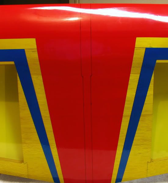
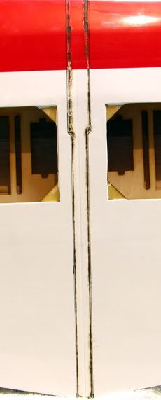
After the epoxy on the wing cured, I was inspecting the joint and double checking all the measurements when I spotted this.
And this.
In case it’s not obvious, that’s light you see coming through the gap between the wing and fuse! I think this is probably typical of profile ships, at least it was on all three Fazers I’ve built over the years.
While I would have preferred to see a better fit, I don’t think this is a big deal. To address it, I assembled the necessary supplies.I considered using a mixture of epoxy and micro balloons, but was not confident I could get all the gaps filled AND keep them filled while it cured. Gorilla Glue is prized for its foaming action and tremendous strength, so I figured this was the perfect place to use it. Had I inspected the joint more closely before gluing it, I probably would have just used GG the first time around. Live and learn, eh?
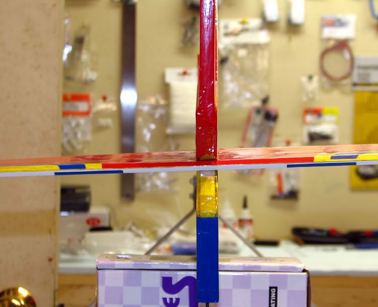
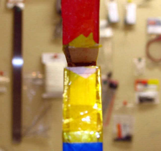
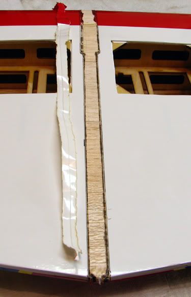
Anyway, I soaked a strip of index card in plain water and then ran it inside the gap several times to get the area moist. Then I put a tablespoon or so of GG into the small ziplock bag and snipped off one corner. I use the resulting “pastry bag” to squirt the GG into the gap. The flat bag was very easy to insert deep into the gap. I just slowly pulled it out as the GG went in. I repeated this on all 4 sides of the joint and cleaned of the excess. I returned every few minutes to wipe away the excess glue as it oozed out of the gap.
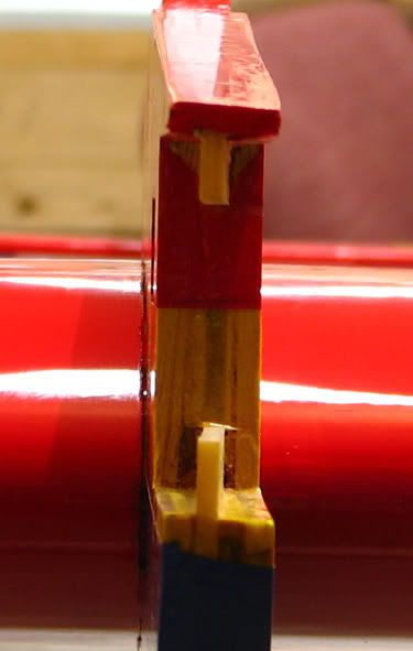
Anyone who has ever used this stuff, knows that you can’t just walk away after you get the glue in the joint. The very first time I ever used GG I learned this lesson the hard way.
What you’re looking at is a vertical stab that lifted itself out of it’s slot after I installed it with GG and walked away for the night.
Fortunately for me, the plane still flew well and the joint has held up fine. The last thing I managed to do was get the tail servos mounted. These went in without any hacking (or disassembly!) required. I used my Great Planes Dead Center thingy to drill the holes.
Then, like everyone else on the planet seems to do, I hardened the holes with CA and screwed the servos into place.
That’s where I stand as of now. Next up is to install the aileron servos, get all the hinges glued and start working on control linkages.Thanks again to all those who have posted comments and suggestions. Please keep them coming. If left to my own devices, this Edge may end up with a smoke system, auto pilot, parachute drop and sailplane tow hook.
11-12-2006, 07:40 PM
#11
Senior Member
My Feedback: (51)
Join Date: Jul 2002
Location: Ashland, KY
Posts: 5,833
Likes: 0
Received 0 Likes
on
0 Posts
Awe shucks... thanks... We all learn by sharing... and I learned so much online I like to share it right back.
Just like you re doing by doing this build thread. Lots of guys will pick up some great tips through it.
On the gapping in the wing... it is exacerbated by the double taper wing... Can't hardly get away from that...
You're gonna love this plane... it really is one sweet flying, light ARF Profile.
Just like you re doing by doing this build thread. Lots of guys will pick up some great tips through it.
On the gapping in the wing... it is exacerbated by the double taper wing... Can't hardly get away from that...
You're gonna love this plane... it really is one sweet flying, light ARF Profile.
 11-12-2006, 09:11 PM
#13
Senior Member
Thread Starter
Join Date: Jul 2006
Location: Charlottesville,
VA
Posts: 723
Likes: 0
Received 0 Likes
on
0 Posts
Maudib, I hadn't even thought about the effect of the double taper. It makes perfect sense now that you mention it.
Mike, thank you!
Mike, thank you!
11-16-2006, 11:08 PM
#14
Senior Member
Thread Starter
Join Date: Jul 2006
Location: Charlottesville,
VA
Posts: 723
Likes: 0
Received 0 Likes
on
0 Posts
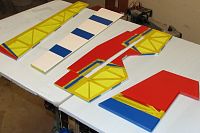
I finally found some time to get a little more work done on the Edge. I’d love to wrap one of these up in just a few day like some of you speed demons, but life just gets in the way and airplanes have to go on the back burner.
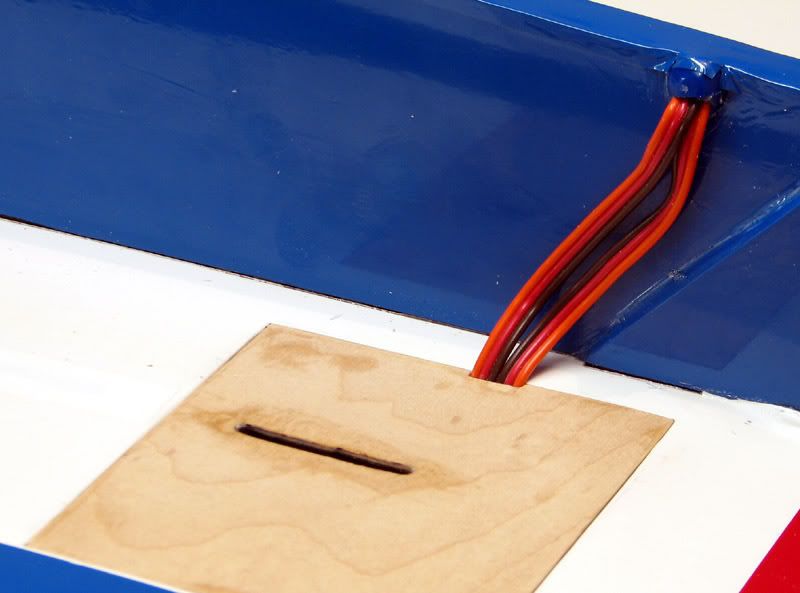
After I got the tail servos mounted, I began to start thinking about routing the servo wires in the channel along the bottom of the fuse. I really like this idea and think it is a very clever way to hide the wires. My hat’s off to Chris and the crew at Extreme Flight. The only part I don’t like is the point where the wires enter and exit the channel.
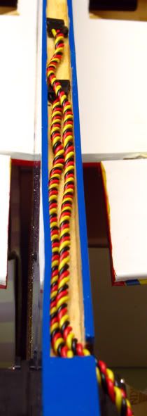
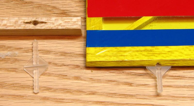
I really would like to have a clean, sealed point of entry so as to keep oil and dirt out. The exit point is probably not as critical, but for the sake of consistency, I’ll have to work on both of them. After a little thought and digging around in my big box of old airplane junk, I found these.
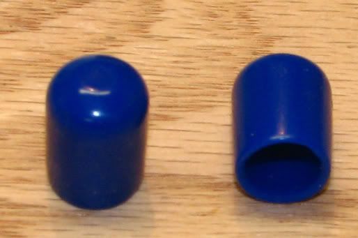
I think Great Planes use to market them as carb covers. They came in a package of 8 or 10 pieces in several different sizes. These blue ones were way to small for any engines I had, so they ended up in the junk box. Here is what I hope to do with them.
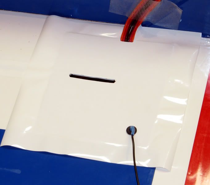
I figured if I could cut or burn some slits or holes in the cap, I might be able to feed the wires through it and then glue the cap in place with some silicone sealant. After a little work with a hot soldering iron, I ended up with this.
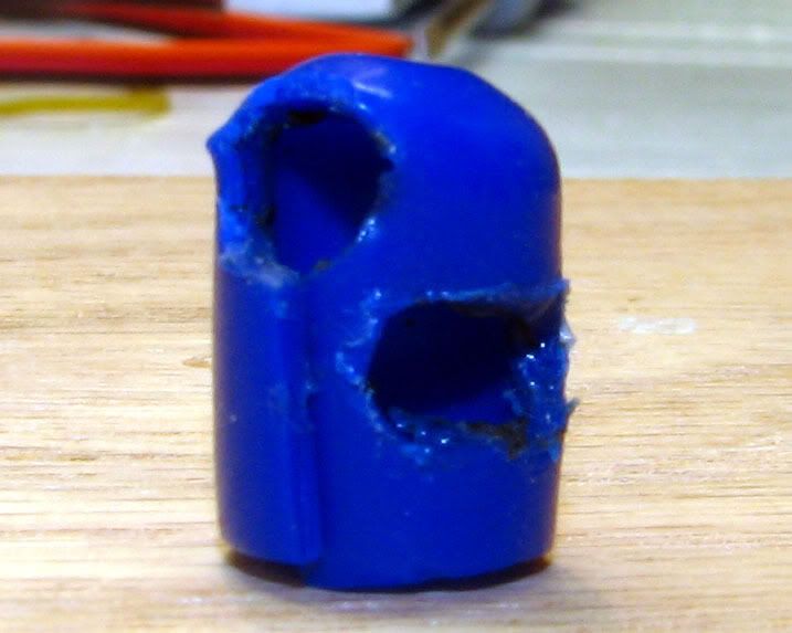
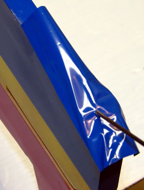
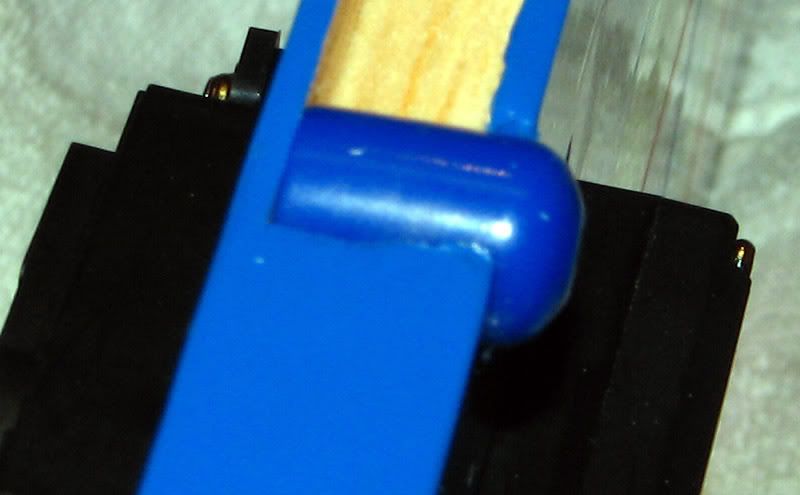
It’s all hacked up and looks pretty ragged, but after tucking it into the channel and packing the edges with silicone, it doesn’t look too terrible.
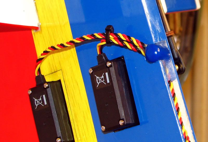
When it fully cures, I’ll iron on the strip of blue covering right up against the edge of the cap and hopefully it will be nice and fuel proof.
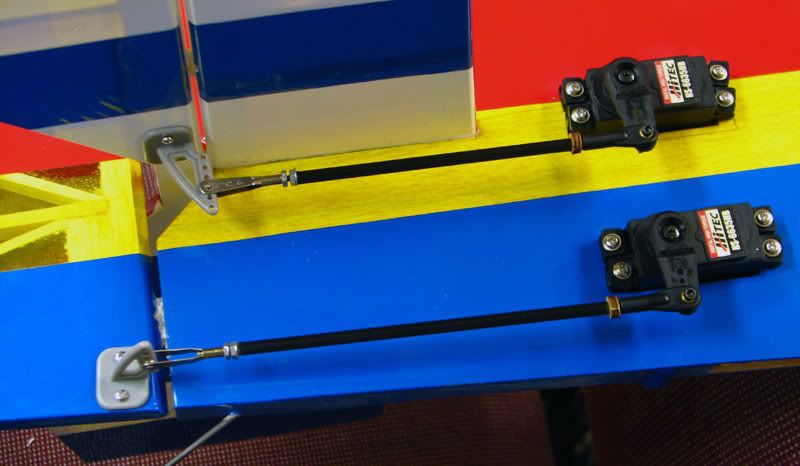
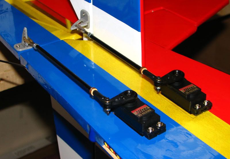
The linkages for the tail went together pretty smoothly. I used the stock horns and think they are very high quality. The stock rods and ball joints are also very nice pieces, but as far as I can tell, they are metric and I like to have consistent fittings among my planes so I chose to go with 2-56 all thread inside a .157” carbon fiber tube. The tube is captured on one end by a washer and 2-56 nut with loctite and on the other by a small plywood disc left over from my Extreme Flight Extra 300E. The servo end has a Dubro link and the horn end has a Sullivan clevis and jam nut. With ATV maxed out on the TX, I was happy to see that I didn’t have to use the innermost holes on the horns. This should provide plenty of mechanical advantage, thereby minimizing the load on the servos and consequently, battery drain. It also allows for maximum resolution, not that my rusty old thumbs can tell much difference.
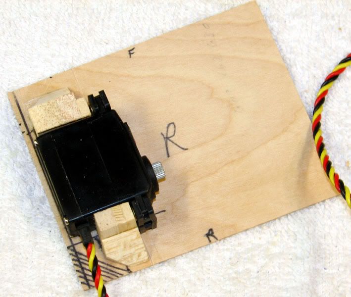
After getting the tail squared away, I began to check out the aileron servo installation.
The existing cutouts in the wing swallowed up the HS5245s so I cut some aircraft ply rails to take up the slack.
These are glued in place and drying as I type this. While messing around with the aileron servos, I came up with an idea to help reduce weight on the nose. As much as I like the idea of having the throttle servo inches behind the motor (ease of set up and simplicity of linkage), I think I’m going to mount the throttle servo adjacent to the right aileron servo. I glued two small strips of aircraft ply to make a small platform for it.
It should be relatively simple to route a nyrod through the leading edge of the wing.
This should no more difficult or less elegant than running the throttle servo wire through the same spot. I guess the next chore will be to mount the aileron servos and linkages, get the throttle servo and linkages in place, and then start to think about getting the engine mounted. Hopefully I can get a lot done this weekend.
After I got the tail servos mounted, I began to start thinking about routing the servo wires in the channel along the bottom of the fuse. I really like this idea and think it is a very clever way to hide the wires. My hat’s off to Chris and the crew at Extreme Flight. The only part I don’t like is the point where the wires enter and exit the channel.
I really would like to have a clean, sealed point of entry so as to keep oil and dirt out. The exit point is probably not as critical, but for the sake of consistency, I’ll have to work on both of them. After a little thought and digging around in my big box of old airplane junk, I found these.
I think Great Planes use to market them as carb covers. They came in a package of 8 or 10 pieces in several different sizes. These blue ones were way to small for any engines I had, so they ended up in the junk box. Here is what I hope to do with them.
I figured if I could cut or burn some slits or holes in the cap, I might be able to feed the wires through it and then glue the cap in place with some silicone sealant. After a little work with a hot soldering iron, I ended up with this.
It’s all hacked up and looks pretty ragged, but after tucking it into the channel and packing the edges with silicone, it doesn’t look too terrible.
When it fully cures, I’ll iron on the strip of blue covering right up against the edge of the cap and hopefully it will be nice and fuel proof.
The linkages for the tail went together pretty smoothly. I used the stock horns and think they are very high quality. The stock rods and ball joints are also very nice pieces, but as far as I can tell, they are metric and I like to have consistent fittings among my planes so I chose to go with 2-56 all thread inside a .157” carbon fiber tube. The tube is captured on one end by a washer and 2-56 nut with loctite and on the other by a small plywood disc left over from my Extreme Flight Extra 300E. The servo end has a Dubro link and the horn end has a Sullivan clevis and jam nut. With ATV maxed out on the TX, I was happy to see that I didn’t have to use the innermost holes on the horns. This should provide plenty of mechanical advantage, thereby minimizing the load on the servos and consequently, battery drain. It also allows for maximum resolution, not that my rusty old thumbs can tell much difference.
After getting the tail squared away, I began to check out the aileron servo installation.
The existing cutouts in the wing swallowed up the HS5245s so I cut some aircraft ply rails to take up the slack.
These are glued in place and drying as I type this. While messing around with the aileron servos, I came up with an idea to help reduce weight on the nose. As much as I like the idea of having the throttle servo inches behind the motor (ease of set up and simplicity of linkage), I think I’m going to mount the throttle servo adjacent to the right aileron servo. I glued two small strips of aircraft ply to make a small platform for it.
It should be relatively simple to route a nyrod through the leading edge of the wing.
This should no more difficult or less elegant than running the throttle servo wire through the same spot.
I guess the next chore will be to mount the aileron servos and linkages, get the throttle servo and linkages in place, and then start to think about getting the engine mounted. Hopefully I can get a lot done this weekend.
11-17-2006, 10:02 AM
#15
Member
Join Date: Jan 2003
Location: Shawnee,
KS
Posts: 61
Likes: 0
Received 0 Likes
on
0 Posts
JustEric,
Thanks for doing this thread. I am in the middle of assembly myself and we have very similar ideas. I have the Sulivan tail wheel on mine. It worked on my Mojo so far so I thought it would be good here. I ended up doing the wedge thing on the tail also. I plan on using my MVVS .49 with pipe so I hope the CG comes out about right. I do not want the battery on the outside if at all possible. I am anal about loose covering edges so I have spent more time than I probably should have with a hot iron gettting everything sealed down. I seal any bare wood with thinned epoxy also. I am at the point of installing the radio and motor now so I'l be watching your thread. Thanks again. I like the overall covering scheme but not wild about the Edge 540 lettering so I might leave it off and add my own or something on one wing. I have flown one of these a little and liked it very much. The quality of the ARF is great.
Thanks for doing this thread. I am in the middle of assembly myself and we have very similar ideas. I have the Sulivan tail wheel on mine. It worked on my Mojo so far so I thought it would be good here. I ended up doing the wedge thing on the tail also. I plan on using my MVVS .49 with pipe so I hope the CG comes out about right. I do not want the battery on the outside if at all possible. I am anal about loose covering edges so I have spent more time than I probably should have with a hot iron gettting everything sealed down. I seal any bare wood with thinned epoxy also. I am at the point of installing the radio and motor now so I'l be watching your thread. Thanks again. I like the overall covering scheme but not wild about the Edge 540 lettering so I might leave it off and add my own or something on one wing. I have flown one of these a little and liked it very much. The quality of the ARF is great.
11-17-2006, 02:55 PM
#16
Senior Member
Thread Starter
Join Date: Jul 2006
Location: Charlottesville,
VA
Posts: 723
Likes: 0
Received 0 Likes
on
0 Posts
Hi Jerry,
No need to thank me, it's my pleasure. Your Edge should be a rocket with that big piped MVVS. I'd love to see it fly. I feel the same way you do about the battery on the outside. As much as I hate the idea, I'd probably choose to add dead weight or perhaps flying wires to the tail surfaces....might as well be functional, right?. I guess I'll just wait and see how everything turns out.
I keep changing my mind about the included decals. Sometimes I like them and sometimes I'm convinced that I should just toss them. If you end up doing something different, please post a pic so we can check it out.
I haven't flown one of these puppies before. In fact the only profile I've ever flown is a Fazer (I've built three of them over the years!), and I like it but it's just not a 3D machine.
And since you're building yours right now, feel free to post some pics of your progress so we can compare notes.
No need to thank me, it's my pleasure.
Your Edge should be a rocket with that big piped MVVS. I'd love to see it fly. I feel the same way you do about the battery on the outside. As much as I hate the idea, I'd probably choose to add dead weight or perhaps flying wires to the tail surfaces....might as well be functional, right?. I guess I'll just wait and see how everything turns out. I keep changing my mind about the included decals. Sometimes I like them and sometimes I'm convinced that I should just toss them. If you end up doing something different, please post a pic so we can check it out.
I haven't flown one of these puppies before. In fact the only profile I've ever flown is a Fazer (I've built three of them over the years!), and I like it but it's just not a 3D machine.
And since you're building yours right now, feel free to post some pics of your progress so we can compare notes.
11-17-2006, 03:07 PM
#17
Member
Join Date: Jan 2003
Location: Shawnee,
KS
Posts: 61
Likes: 0
Received 0 Likes
on
0 Posts
This plane will be a lot more capable than the Fazer. I had one also. This will be "looser" in the air. Start on low rates and you'll have no trouble. I was thinking of adding a tapered strip of color on the top of the wing like a starburst effect just to be different. I personally did not care for the silver canopy. Mine peeled right off and I replaced it with Black ultracoat. I like it.
 ][
11-17-2006, 07:05 PM
][
11-17-2006, 07:05 PM
#20
Senior Member
My Feedback: (8)
Join Date: Dec 2004
Location: fitchburg,
MA
Posts: 422
Likes: 0
Received 0 Likes
on
0 Posts
i had a ys 63 and was recommended to use a master airscrew 13x5 (i had trouble running it, mostly just not familiar w/ys, replaced it w/a incredibly vibrating saito .82). according to ys, they say to run about 11,500, that's what you get w/the 13x5. the 13x6 (too fast for a 3d) will give a little over 10k, so will a 14x4w (which is what i use on my os 70 fs, ucando .46). i use a mpi miracle switch w/6v regulator & 900 mah 2s lipo (total about 3 ounces), r/c reporter e version (plane locater and gives battery voltage). i use hs 81 on throttle, hs 5245 mg on rudder, tower or hobbico cs35mg on ailerons and elev. (about 70 oz on 6v and weigh 1 ounce)
i am poking around looking for a mousse can muffler plan, the search brought up your thread. i just bought a new os 55 ax for one of my omp edge 540 profile, i built w/a removeable wing (the only way i can transport it). i'll keep looking for a plan, but if you can would you give me some info? i have been told to use a white rain mousse can from walmart, but it appears that they are now made form plastic, however, the is a new (small) one from suave that looks about the right size.
jon b
11-17-2006, 08:15 PM
#21
Senior Member
Thread Starter
Join Date: Jul 2006
Location: Charlottesville,
VA
Posts: 723
Likes: 0
Received 0 Likes
on
0 Posts
JB, the recipe I used for both my MCPs is [link=http://webpages.charter.net/rcfu/ConstGuide/MCM.html]here.[/link] I'm very pleased with the results on my old .40 SF. If memory serves, I'm getting about 10,500 on a APC 12.25 x 3.75. I'm sure that's just a fraction of what the 55 AX will do. I'd love to get that kind of power out of my 40. I get my mousse cans from walmart also. You should still be able to find them made of aluminum. I'm going to have to check into the MPI miracle switch. I've seen it mentioned enough times to know that a lot of people like them.
Jerry, your idea for a black canopy area sounds pretty good. I may just steal that.
Edited to correct RPM estimate on the .40 SF.
I'd love to get that kind of power out of my 40. I get my mousse cans from walmart also. You should still be able to find them made of aluminum. I'm going to have to check into the MPI miracle switch. I've seen it mentioned enough times to know that a lot of people like them.Jerry, your idea for a black canopy area sounds pretty good. I may just steal that.
Edited to correct RPM estimate on the .40 SF.
11-21-2006, 12:39 PM
#23
My Feedback: (6)
Join Date: Dec 2001
Location: Georgetown,
IN
Posts: 1,515
Likes: 0
Received 0 Likes
on
0 Posts
Do not worry about those little gaps around the wing. I have yet to see a profile that did not have a little. In fact, I would say that the EF edge is one of the better ones in this area. I just shoot it with accelerator and flow some medium in it, trust me the wings do not come out of profiles. Good build thread, you put a lot of effort into them.
Jeff
Jeff
11-21-2006, 02:28 PM
#24
Member
Join Date: Jan 2003
Location: Shawnee,
KS
Posts: 61
Likes: 0
Received 0 Likes
on
0 Posts
I prefer to 30 min epoxy the wing in cleaning up with alcohol until it sets up. Then I come back with 5 min epoxy and a toothpick and let it fill any gaps. Again cleaning up with alcohol. Dries nice and smooth. CA works also but I always have more trouble cleaning the stuff up and it seems to run all over. Just personal preference.
12-14-2006, 11:51 PM
#25
Senior Member
Thread Starter
Join Date: Jul 2006
Location: Charlottesville,
VA
Posts: 723
Likes: 0
Received 0 Likes
on
0 Posts
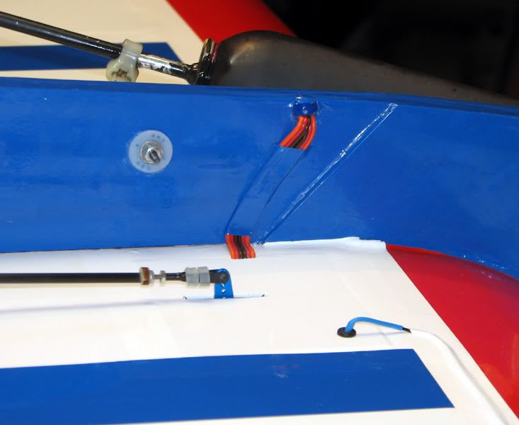
Wow, I haven’t posted an update in nearly a month. I didn’t realize I had let it go this long. Since I maidened the plane today, I guess I need to wrap this thing up. I think the last thing discussed was the throttle servo location. As it turns out, I nearly regretted relocating it because it looked like the plane was going to be tail heavy. But after sliding the engine forward on the rails, it balanced just about perfectly. Here is a pic of the finalized location and linkage installed. I CA’ed a small scrap of balsa to the spar and used that as an anchor for the outer sleeve of the pushrod. Oh, and in case it’s not obvious, the red residue on the nylon clevis is blood. At this point I can’t even remember exactly what happened, but I know there is some on the throttle arm as well.
Although I didn’t take pics of it, I mocked up the aileron servos in the intended position but was not at all pleased with the results. The extreme throw required caused a HUGE amount of lateral movement in the pushrod. It was so bad that I was about to enlarge the slots in the wing sheeting to allow for all the side-to-side movement. Now, I may have been doing something wrong, but the more I thought about it, the more certain I was that I could do it better.
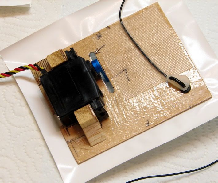
I know Jeff recommended just following the instructions, but I have this personality flaw that somehow prevents me from doing that. I don’t think I’ve ever been able to NOT deviate somewhere. In this case, I decided to lay the servos on their side so the servo arm moved in the same plane as the control horn. At first I was going to build a platform on the existing mounting tray, but then I decided on a different option. I built replacement hatches out of some scrap lite ply and epoxied mounting rails to them.
Here is a shot of trial fitting the hatch into place.
The hatch for the left side was also drilled for the antenna exit. I made it slightly oversized so I could put in a servo grommet and help protect the wire. I also used a servo arm cut-off as a strain relief device for the antenna wire. It’s easy to see in this pic that I smeared a light coat of epoxy on the entire undersurface of the hatch. I also used some sort of medical grade tape to tape the antenna wire to the underside of the hatch for a bit more protection.
I know Jeff will probably give me a hard time for this next bit, but that’s ok. After spending extra time making the hatches fit the openings very snugly, I didn’t want to ruin the look by affixing them with screws. I decided to cut the covering about an inch bigger all the way around and lock the hatches into place with it. Here are the two completed hatches along with the receiver and receiver battery, a 1400 mah nmh pack, ready to be ironed into position.
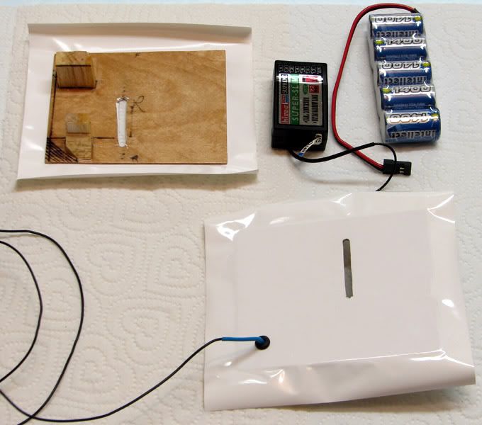
I know “iron-on servo mounting“ may be somewhat unorthodox, but I’m prepared to inspect the hatches routinely to make sure they stay secure. I’m also willing to cut the covering if I need to get inside the wing at any point in the future. Here is a mock-up of how the hatches fit into place.
Here is a shot of the hatch area after everything has been sealed up. I also used a strip of covering to affix the servo wires from the tail to the side of the fuse. I would have liked to cover them completely, but couldn’t come up with a good way to do it. The hatches and servos are rock solid with absolutely no play. You can also see where I used a long strip of covering to iron the antenna to the wing. It runs all the way to the wingtip, where the excess is allowed to fly in the breeze.
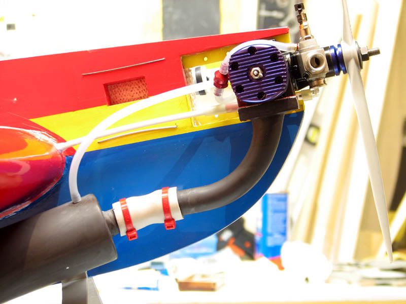
As is probably obvious in the last pic, I have a mousse can pipe mounted on the plane. The other end is attached to the J’EN .57. After thinking more about the engine options, I decided against the YS .63, mostly because I was anxious to see how the J’EN would run. YS is established and reputable, whereas the J’EN is much more of an unknown and has some documented “issues” that I wanted to see if I could overcome. Here are some shots of it mounted, along with the header and MCP.
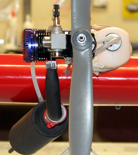
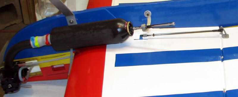
The tank is held in place by rubber bands hooked to the end of U-shaped pieces of music wire that I passed through the fuse. Since I didn’t mount the throttle servo in the intended location, I didn’t need the balsa standoffs. Also, I didn’t want to make big holes for nylon tie wraps, so I went with something more simple.
So, how did it fly, you ask? Well, to start with, I was more nervous than usual because the CG was a little rearward of the recommended starting position. However, it was within the acceptable range, so I decided to go with that and see what I thought. I had already run the J’EN for close to an hour on the bench, so the needles were pretty close. The engine started easily and the plane range checked fine. I taxied out and slowly eased the throttle forward. The engine stumbled a bit, but picked up within a couple seconds and she was airborne. I never can seem to remember how many clicks (or beeps in this case) it takes to trim a plane on it’s maiden flight and today was no exception. I’m pretty sure I needed a little up and a little right aileron, but nothing out of the ordinary.
Anyway, I made a few passes at a nice safe altitude and then tried a few basic maneuvers. I’m no 3D pilot, so I can’t comment on much more than simple loops, rolls, spins etc. The plane did them all with no complaints. The engine is WAY more than is needed for normal sport flying……it will easily climb out of sight without slowing down. However, since I plan to use this beast as a 3D trainer, I know I’ll soon need all that excess power. I was flying with an APC 13 x 4W. The J’EN turned it 11,300 on the ground and I richened it to about 11,000 before taking off. This engine really is a powerhouse. On the bench, I had it up to about 11,600 with the same prop, but it was much colder at the time (mid 30’s versus mid 60’s today).
The first two flight ended with deadstick landings. I was prepared for this and landed with no problems. I leaned the low end about one eighth of a turn each time, and the next three flights were all fine; no more deadsticks. The transition is still not what it should be, but I’m not giving up yet. I will keep leaning the low end unless and until it starts to cause other problems.
Well, I guess that’s about it for my little report. I never realized how time consuming it is to document all the steps one must take to assemble an ARF. My hat is off to you guys who do it all the time. It is beneficial, however, because it’s almost like you have a crowd of people looking over your shoulder and you don’t want to screw up in front of them. I made some mistakes on this plane, but not as many as I would have if I had rushed through it like usual. Thanks to all those who lent me their ears and their thoughts.
Erik
I think the last thing discussed was the throttle servo location. As it turns out, I nearly regretted relocating it because it looked like the plane was going to be tail heavy. But after sliding the engine forward on the rails, it balanced just about perfectly. Here is a pic of the finalized location and linkage installed. I CA’ed a small scrap of balsa to the spar and used that as an anchor for the outer sleeve of the pushrod. Oh, and in case it’s not obvious, the red residue on the nylon clevis is blood. At this point I can’t even remember exactly what happened, but I know there is some on the throttle arm as well. Although I didn’t take pics of it, I mocked up the aileron servos in the intended position but was not at all pleased with the results. The extreme throw required caused a HUGE amount of lateral movement in the pushrod. It was so bad that I was about to enlarge the slots in the wing sheeting to allow for all the side-to-side movement. Now, I may have been doing something wrong, but the more I thought about it, the more certain I was that I could do it better.
I know Jeff recommended just following the instructions, but I have this personality flaw that somehow prevents me from doing that.
I don’t think I’ve ever been able to NOT deviate somewhere. In this case, I decided to lay the servos on their side so the servo arm moved in the same plane as the control horn. At first I was going to build a platform on the existing mounting tray, but then I decided on a different option. I built replacement hatches out of some scrap lite ply and epoxied mounting rails to them.Here is a shot of trial fitting the hatch into place.
The hatch for the left side was also drilled for the antenna exit. I made it slightly oversized so I could put in a servo grommet and help protect the wire. I also used a servo arm cut-off as a strain relief device for the antenna wire. It’s easy to see in this pic that I smeared a light coat of epoxy on the entire undersurface of the hatch. I also used some sort of medical grade tape to tape the antenna wire to the underside of the hatch for a bit more protection.
I know Jeff will probably give me a hard time for this next bit, but that’s ok.
After spending extra time making the hatches fit the openings very snugly, I didn’t want to ruin the look by affixing them with screws. I decided to cut the covering about an inch bigger all the way around and lock the hatches into place with it. Here are the two completed hatches along with the receiver and receiver battery, a 1400 mah nmh pack, ready to be ironed into position.I know “iron-on servo mounting“ may be somewhat unorthodox, but I’m prepared to inspect the hatches routinely to make sure they stay secure. I’m also willing to cut the covering if I need to get inside the wing at any point in the future. Here is a mock-up of how the hatches fit into place.
Here is a shot of the hatch area after everything has been sealed up. I also used a strip of covering to affix the servo wires from the tail to the side of the fuse. I would have liked to cover them completely, but couldn’t come up with a good way to do it. The hatches and servos are rock solid with absolutely no play. You can also see where I used a long strip of covering to iron the antenna to the wing. It runs all the way to the wingtip, where the excess is allowed to fly in the breeze.
As is probably obvious in the last pic, I have a mousse can pipe mounted on the plane. The other end is attached to the J’EN .57. After thinking more about the engine options, I decided against the YS .63, mostly because I was anxious to see how the J’EN would run. YS is established and reputable, whereas the J’EN is much more of an unknown and has some documented “issues” that I wanted to see if I could overcome. Here are some shots of it mounted, along with the header and MCP.
The tank is held in place by rubber bands hooked to the end of U-shaped pieces of music wire that I passed through the fuse. Since I didn’t mount the throttle servo in the intended location, I didn’t need the balsa standoffs. Also, I didn’t want to make big holes for nylon tie wraps, so I went with something more simple.
So, how did it fly, you ask? Well, to start with, I was more nervous than usual because the CG was a little rearward of the recommended starting position. However, it was within the acceptable range, so I decided to go with that and see what I thought. I had already run the J’EN for close to an hour on the bench, so the needles were pretty close. The engine started easily and the plane range checked fine. I taxied out and slowly eased the throttle forward. The engine stumbled a bit, but picked up within a couple seconds and she was airborne. I never can seem to remember how many clicks (or beeps in this case) it takes to trim a plane on it’s maiden flight and today was no exception. I’m pretty sure I needed a little up and a little right aileron, but nothing out of the ordinary.
Anyway, I made a few passes at a nice safe altitude and then tried a few basic maneuvers. I’m no 3D pilot, so I can’t comment on much more than simple loops, rolls, spins etc. The plane did them all with no complaints. The engine is WAY more than is needed for normal sport flying……it will easily climb out of sight without slowing down. However, since I plan to use this beast as a 3D trainer, I know I’ll soon need all that excess power. I was flying with an APC 13 x 4W. The J’EN turned it 11,300 on the ground and I richened it to about 11,000 before taking off. This engine really is a powerhouse. On the bench, I had it up to about 11,600 with the same prop, but it was much colder at the time (mid 30’s versus mid 60’s today).
The first two flight ended with deadstick landings. I was prepared for this and landed with no problems. I leaned the low end about one eighth of a turn each time, and the next three flights were all fine; no more deadsticks. The transition is still not what it should be, but I’m not giving up yet. I will keep leaning the low end unless and until it starts to cause other problems.
Well, I guess that’s about it for my little report. I never realized how time consuming it is to document all the steps one must take to assemble an ARF. My hat is off to you guys who do it all the time. It is beneficial, however, because it’s almost like you have a crowd of people looking over your shoulder and you don’t want to screw up in front of them.
I made some mistakes on this plane, but not as many as I would have if I had rushed through it like usual. Thanks to all those who lent me their ears and their thoughts. Erik