


AD Diamond build thread
 10-02-2013 | 01:47 AM
#1

Thread Starter

I have started a build thread on my blog:
http://www.ultimate-jets.net/blogs/j...d-presentation
As usual, I will also back it up on RCU.
All the latest and the additional pictures will be posted on our web Facebook page:
https://www.facebook.com/pages/Ultim...23469480996666
Please like this page to receive the latest pictures update from the build.
The first production airframe is on the way to me.
This is still a prototype stage kit but we will use it to fine tune the production process.
All the internals on this model will be identical on the production kits. So I will take the opportunity of this build thread to show you how this model is made of.
Here are a few pictures of this exact airframe during the production stage.
The wings:

The main spar up to the landing gear plate is made of aero grade Finnish birch plywood. The main spar is 12 mm thick and virtually indestructible. The gear false ribs are also made from the same ply.
The rear flight control spar is made of thick balsa wood. The wing skin is vacuum moulded from drilled Airex/ glass fiber sandwich with a thick carbon fiber patch joining both the main and front spars.
The fin:

The same type of construction is used for the fin: vacuum moulded drilled Airex/ glass sandwich with thick aero grade plywood main and rear spars. Eric took a special care at sizing this area as the horizontal stabilizer is mounted on top of the fin and it is essential that the whole assembly stay super stiff in all situations.
The top of the main fin spar has a T shape that includes two ribs and the small tube section required to slide the two half horizontal stabilizers. The stabilizers tube is in one piece.
The wing, rudder and stabilizer tubes are made from aero grade AU4G that is used on AD drones as well as all the models from the Scorpion to the super scale Rafale.
http://www.ultimate-jets.net/blogs/j...d-presentation
As usual, I will also back it up on RCU.
All the latest and the additional pictures will be posted on our web Facebook page:
https://www.facebook.com/pages/Ultim...23469480996666
Please like this page to receive the latest pictures update from the build.
The first production airframe is on the way to me.
This is still a prototype stage kit but we will use it to fine tune the production process.
All the internals on this model will be identical on the production kits. So I will take the opportunity of this build thread to show you how this model is made of.
Here are a few pictures of this exact airframe during the production stage.
The wings:
The main spar up to the landing gear plate is made of aero grade Finnish birch plywood. The main spar is 12 mm thick and virtually indestructible. The gear false ribs are also made from the same ply.
The rear flight control spar is made of thick balsa wood. The wing skin is vacuum moulded from drilled Airex/ glass fiber sandwich with a thick carbon fiber patch joining both the main and front spars.
The fin:
The same type of construction is used for the fin: vacuum moulded drilled Airex/ glass sandwich with thick aero grade plywood main and rear spars. Eric took a special care at sizing this area as the horizontal stabilizer is mounted on top of the fin and it is essential that the whole assembly stay super stiff in all situations.
The top of the main fin spar has a T shape that includes two ribs and the small tube section required to slide the two half horizontal stabilizers. The stabilizers tube is in one piece.
The wing, rudder and stabilizer tubes are made from aero grade AU4G that is used on AD drones as well as all the models from the Scorpion to the super scale Rafale.
Last edited by olnico; 10-02-2013 at 01:53 AM.
 10-02-2013 | 02:03 AM
#2
Thread Starter
The AD Diamond photo album will be updated here:
https://www.facebook.com/media/set/?...0996666&type=3
We will be working in close cooperation with the factory in France to offer specific features for our customer: full carbon bypass optimized for our JB-220, integrated control links, virtual wind tunnel simulation and control surfaces force calculation as we always do for all our kits.
We will also offer dedicated schemes. Do not hesitate to post a scheme request on these pages.
10-02-2013 | 10:28 AM
#3
Thread Starter
For those who were wondering how the engine installs in the plane, here is a good picture of it.

The engine rails are vertical. The big problem with this is that it makes the engine sit with the kero burner a 3 o'clock for the start sequence.
Some engines don't like this at all.
I am designing a different full bypass system for the production kits that will allow the engine to sit upright and have the kero burner at 12 o'clock.
The engine will slide on a craddle into the plane. That will include the middle section of the carbon bypass .
This system is OK to use for engines that can rotate in their mounting bracket like the Jetcat series though.
Note that the maximum size that fits into this fuselage is the 160 form factor.
This makes the JB-220 the best engine choice for stratospheric performance on this plane...
Last edited by olnico; 10-02-2013 at 10:31 AM.
10-30-2013 | 06:05 PM
#4
Thread Starter
A few pictures from the Diamond build:
The Behotec JB-220 is a perfect fit for this plane and optimum choice. Shown here removed from its tray. The bypass system is being made at the mometn and I'll have pictures of it in a couple of weeks from now.

The tailpipe is of high quality and made by Grumania.

The rear fuselage plywood structure as seen from the back. Made from aero grade Finnish birch ply. The clearance on the top od the bulkhead is due to its 45 degrees tilt in the fuselage.
The vertical former ensures a good transfer of the engine efforts ( 220 N ) between the rear and the front of the fuselage structure. It also provides additional stength to the fin tube. This vetical structure is seen on top and bottom of the fuselage in this area.

The same structure as seen from the canopy area. The large vertical former indents into the inlet duct bulkhead.

Another view of this vertical former. It passes through the fin root rib and is glued to the fin tube sleeve.


The main wing tube sleeve is encased in a plywood structure. This is the rear view of it. This plywood structrue comprises of a horizontal floor that holds the cockpit, fuel cells and some of the rc/ engine components.
It is bonded to 3 plywood vertical bulkheads that act as fuselage spars.

This view of the fuselage shows these vertical bulkheads.

The nose gear box. 100% aero grade Finnish birch plywood. It also includes the nose structure blind nuts as seen on the top. A large carbon fiber reinforcement ensures the rigidity of the flat bottom.

The nose plywood structure. It holds the vertical front retract ( rear face ) and the batteries ( front tray ). It bolts to the structure with 4 M4 screws.

A view of the front section of the fuselage where the nose structure bolts.

A view of the nose structure assembled. The nose cone slides onto it via a rail system and snaps onto a large rare earth magnet. Plenty of room here for all kinds of batteries") .
.
3 batteries of 4000 mAh are enough to balance the aircraft perfectly.

The main gear opening. I am going to develop a doors option for this kit.

The rudder live hinging area. All hinging spars are made from liteply on this plane.

The elevator hinging area. Note the elevator servo bulge.

The elevator uses a wide aero grade carbon fiber tube and two aluminium incidence pins per side.

The fin tube is made from an aero grade AU4G tube.

Overall, this is the toughest airplane structure I've seen fro a long time. On par with BVM products on that matter.
Dry weight is forecast to be 18 kgs on this one and 22 kgs for takeoff.
Eric said that I might find it too light in flight actualy. We'll see...
The Behotec JB-220 is a perfect fit for this plane and optimum choice. Shown here removed from its tray. The bypass system is being made at the mometn and I'll have pictures of it in a couple of weeks from now.
The tailpipe is of high quality and made by Grumania.
The rear fuselage plywood structure as seen from the back. Made from aero grade Finnish birch ply. The clearance on the top od the bulkhead is due to its 45 degrees tilt in the fuselage.
The vertical former ensures a good transfer of the engine efforts ( 220 N ) between the rear and the front of the fuselage structure. It also provides additional stength to the fin tube. This vetical structure is seen on top and bottom of the fuselage in this area.
The same structure as seen from the canopy area. The large vertical former indents into the inlet duct bulkhead.
Another view of this vertical former. It passes through the fin root rib and is glued to the fin tube sleeve.
The main wing tube sleeve is encased in a plywood structure. This is the rear view of it. This plywood structrue comprises of a horizontal floor that holds the cockpit, fuel cells and some of the rc/ engine components.
It is bonded to 3 plywood vertical bulkheads that act as fuselage spars.
This view of the fuselage shows these vertical bulkheads.
The nose gear box. 100% aero grade Finnish birch plywood. It also includes the nose structure blind nuts as seen on the top. A large carbon fiber reinforcement ensures the rigidity of the flat bottom.
The nose plywood structure. It holds the vertical front retract ( rear face ) and the batteries ( front tray ). It bolts to the structure with 4 M4 screws.
A view of the front section of the fuselage where the nose structure bolts.
A view of the nose structure assembled. The nose cone slides onto it via a rail system and snaps onto a large rare earth magnet. Plenty of room here for all kinds of batteries
.3 batteries of 4000 mAh are enough to balance the aircraft perfectly.
The main gear opening. I am going to develop a doors option for this kit.
The rudder live hinging area. All hinging spars are made from liteply on this plane.
The elevator hinging area. Note the elevator servo bulge.
The elevator uses a wide aero grade carbon fiber tube and two aluminium incidence pins per side.
The fin tube is made from an aero grade AU4G tube.
Overall, this is the toughest airplane structure I've seen fro a long time. On par with BVM products on that matter.
Dry weight is forecast to be 18 kgs on this one and 22 kgs for takeoff.
Eric said that I might find it too light in flight actualy. We'll see...

 10-30-2013 | 08:43 PM
#8
Thread Starter
They are not. We've been using them for over 15 years without any problem on over 200 planes of all sizes, speed ranges ( up to 300 mph on the SuperPhoenix ), scale/ sport planes.
However I am working on the flight controls cinematic right now and might change this.
However I am working on the flight controls cinematic right now and might change this.
 10-30-2013 | 09:07 PM
#10

My Feedback: (48)
First of all a 8711 will not fit in it. Made for a 8411 possibly? One broke in my hand tonight just examining. So maybe they can do 300 in a super Phoenix but there not ground taxiing or mounting 8711's in my Diamond! I would never mount a servo to plastic! Minimalistic approach might work for 15 yrs and 1 day. There are much better systems than this 15 yr old one.
scott
10-31-2013 | 11:40 PM
#12
Thread Starter
10-31-2013 | 11:45 PM
#13
Thread Starter
First of all a 8711 will not fit in it. Made for a 8411 possibly? One broke in my hand tonight just examining. So maybe they can do 300 in a super Phoenix but there not ground taxiing or mounting 8711's in my Diamond! I would never mount a servo to plastic! Minimalistic approach might work for 15 yrs and 1 day. There are much better systems than this 15 yr old one.
scott
scott
11-01-2013 | 12:24 AM
#14
Thread Starter
Here is an explanation of the design work that goes into our models regarding the flight controls setup. It gives you an idea of how much thoughts go into making a new model and releasing it for production.
We have currently 3 prototypes at different stages.
The first one is being extensively test flown by our team in France.
The second one is in Houston with Scott and is being built right now.
#3 is the first production unit test airframe and is in my workshop. This is the one you're seeing on this thread.
I will test fly it at 4000 ft density altitude to validate all the modifications that have been implemented after the test phase of #1.
The Diamond is an airframe capable of 300 mph top speed with the JB-220 ( remember to use a pitot tube telemetry system to stay below the 200 mph AMA limit ). I have computed the flight controls accordingly.
One first consideration that came to me is that due to the aerodynamics design, the flight controls require very little deflection for the flight. 10 to 15 degrees is the maximum deflection required. This is unusually low and requires a specific geometry design to avoid using the servo at a low ATV rates and stall them due to overstress ( bad mechanical advantage ).
To setup the controls there are two options; use the provided ABS/ carbon covers or make integrated control links. Both methods work fine. We have used the ABS covers in all our planes for 15 years and they perform very well at speeds up to 300 mph with the appropriate geometry. The pushrod force transferred to the cover should not exceed 20 lbf though.
Each method will require a different setup for each flight control. This is because the covers place the servo high in the surface, whereas the integrated controls method would require to place the servo low in the surface on a glued servo tray.
The ABS covers require to have a fairly long control horn to place the pushrod in the appropriate angle relative the cover opening. You will also notice on the sheet that the servo offset is entered accordingly.
Elevator:
The control horn length is 45 mm and the servo arm 9 mm.
A 100 oz.in servo is enough on this control due to the specific geometry.
The pushrod force is less than 8 lbf, which makes the ABS covers suitable for the job as well as Gold Clevises from Sullivan in 4-40.

Aileron:
The control horn length is 45 mm and the servo arm 12 mm.
A 170 oz.in servo is enough on this control.
The pushrod force is less than 9 lbf, which makes the ABS covers suitable for the job as well as Gold Clevises from Sullivan in 4-40.

Rudder:
Note that the rudder is the main control that requires the highest torque due to the size and deflection.
The control horn length is 4 mm and the servo arm 11 mm.
A 220 oz.in servo is required on this control.
The pushrod force is 14 lbf, which makes the ABS covers suitable for the job as well as Gold Clevisses from Sullivan in 4-40.
.

Flaps:
Flaps require a very careful setup. They are very large and need to be deflected to 70 degrees for landing to provide enough drag.
That make the control need a lot of torque for the landing position.
Here is the simulation of the maximum torque required to extend the flaps to 15 degrees at 126 mph. Max extended speed is 116 mph with the recommended servo.
The control horn length is 40 mm and the servo arm 26 mm.
A 300 oz.in servo is enough on this control due to the specific geometry.
The pushrod force is 32 lbf. The ABS covers are not suitable for the job, neither are the Gold Clevisses from Sullivan.
Large ball links with dual horn required on this setup.

The maximum speed for the landing position with a 300 oz.in servo is 70 mph:

I am making specific full carbon fiber servo covers/ support for this setup.
I recommend the excellent Futaba S9156 for this setup, or higher.
We have currently 3 prototypes at different stages.
The first one is being extensively test flown by our team in France.
The second one is in Houston with Scott and is being built right now.
#3 is the first production unit test airframe and is in my workshop. This is the one you're seeing on this thread.
I will test fly it at 4000 ft density altitude to validate all the modifications that have been implemented after the test phase of #1.
The Diamond is an airframe capable of 300 mph top speed with the JB-220 ( remember to use a pitot tube telemetry system to stay below the 200 mph AMA limit ). I have computed the flight controls accordingly.
One first consideration that came to me is that due to the aerodynamics design, the flight controls require very little deflection for the flight. 10 to 15 degrees is the maximum deflection required. This is unusually low and requires a specific geometry design to avoid using the servo at a low ATV rates and stall them due to overstress ( bad mechanical advantage ).
To setup the controls there are two options; use the provided ABS/ carbon covers or make integrated control links. Both methods work fine. We have used the ABS covers in all our planes for 15 years and they perform very well at speeds up to 300 mph with the appropriate geometry. The pushrod force transferred to the cover should not exceed 20 lbf though.
Each method will require a different setup for each flight control. This is because the covers place the servo high in the surface, whereas the integrated controls method would require to place the servo low in the surface on a glued servo tray.
The ABS covers require to have a fairly long control horn to place the pushrod in the appropriate angle relative the cover opening. You will also notice on the sheet that the servo offset is entered accordingly.
Elevator:
The control horn length is 45 mm and the servo arm 9 mm.
A 100 oz.in servo is enough on this control due to the specific geometry.
The pushrod force is less than 8 lbf, which makes the ABS covers suitable for the job as well as Gold Clevises from Sullivan in 4-40.
Aileron:
The control horn length is 45 mm and the servo arm 12 mm.
A 170 oz.in servo is enough on this control.
The pushrod force is less than 9 lbf, which makes the ABS covers suitable for the job as well as Gold Clevises from Sullivan in 4-40.
Rudder:
Note that the rudder is the main control that requires the highest torque due to the size and deflection.
The control horn length is 4 mm and the servo arm 11 mm.
A 220 oz.in servo is required on this control.
The pushrod force is 14 lbf, which makes the ABS covers suitable for the job as well as Gold Clevisses from Sullivan in 4-40.
.
Flaps:
Flaps require a very careful setup. They are very large and need to be deflected to 70 degrees for landing to provide enough drag.
That make the control need a lot of torque for the landing position.
Here is the simulation of the maximum torque required to extend the flaps to 15 degrees at 126 mph. Max extended speed is 116 mph with the recommended servo.
The control horn length is 40 mm and the servo arm 26 mm.
A 300 oz.in servo is enough on this control due to the specific geometry.
The pushrod force is 32 lbf. The ABS covers are not suitable for the job, neither are the Gold Clevisses from Sullivan.
Large ball links with dual horn required on this setup.
The maximum speed for the landing position with a 300 oz.in servo is 70 mph:
I am making specific full carbon fiber servo covers/ support for this setup.
I recommend the excellent Futaba S9156 for this setup, or higher.
Last edited by olnico; 11-01-2013 at 12:26 AM.


 11-01-2013 | 06:20 PM
#17
Thread Starter
 11-01-2013 | 06:21 PM
#18
Thread Starter
I will also post here a full test flight report including stall speeds, recommended takeoff and landing speeds and more...
11-13-2013 | 07:38 AM
#19
Thread Starter
Setting up the controls on the Diamond is fairly straightforward and just like many other ADjets models.
First identify the different control horns from the CNC carbon fiber plate and detach them.
Then scuff and drill the portion of the horns that goes into the flight control. and drill a few holes.

Install each servo into its respective servo hatch. Use some Sikaflex silicon comound to secure it in place. This is mandatory for the flaps servo as the pusrod force on this one can reach over 50 lbs force.
Place the servo hatch on the respective pocket and drill the 4 fastener holes to 1 mm.
Center the servo arm and install the pushrod in position onto the recommended servo arm hole ( see control calc post above ).

Place the servo/ hatch assembly back into the pocket and secure with the supplied countersink screws.
Place the control horn at the end of the pushrod and verify the CNC routed horn reservation . Make it about 1 mm larger than required to enable a good flowing of the glue. I recommend the use of Hysol E-20HP for this job. It is faster to glue all the horns in position at once.

Once all the horns are glued, you can start working on the aircraft loom.
Here is my usual sequence: make the loom, plug it to the receiver, setup the control throw, then secure the servo and hardware.
The latter includes:
. Putting the retainer tab on all clevises
. Putting thread lock on all push rods.
.Putting a drop of white glue on the thread of the servo spline screw ( I don't use thread lock here as is trend to make plastic arms brittle ).
First identify the different control horns from the CNC carbon fiber plate and detach them.
Then scuff and drill the portion of the horns that goes into the flight control. and drill a few holes.
Install each servo into its respective servo hatch. Use some Sikaflex silicon comound to secure it in place. This is mandatory for the flaps servo as the pusrod force on this one can reach over 50 lbs force.
Place the servo hatch on the respective pocket and drill the 4 fastener holes to 1 mm.
Center the servo arm and install the pushrod in position onto the recommended servo arm hole ( see control calc post above ).
Place the servo/ hatch assembly back into the pocket and secure with the supplied countersink screws.
Place the control horn at the end of the pushrod and verify the CNC routed horn reservation . Make it about 1 mm larger than required to enable a good flowing of the glue. I recommend the use of Hysol E-20HP for this job. It is faster to glue all the horns in position at once.
Once all the horns are glued, you can start working on the aircraft loom.
Here is my usual sequence: make the loom, plug it to the receiver, setup the control throw, then secure the servo and hardware.
The latter includes:
. Putting the retainer tab on all clevises
. Putting thread lock on all push rods.
.Putting a drop of white glue on the thread of the servo spline screw ( I don't use thread lock here as is trend to make plastic arms brittle ).
11-13-2013 | 07:41 AM
#20
Thread Starter
The ABS covers have been validated on the first prototype after the test flight program.
However we'll be proposing an option with fully carbon fiber moulded servo covers.
However we'll be proposing an option with fully carbon fiber moulded servo covers.
 12-02-2013 | 09:53 AM
#22
Thread Starter
Here is a screen capture of the CAD file for the carbon fiber servo hatch:
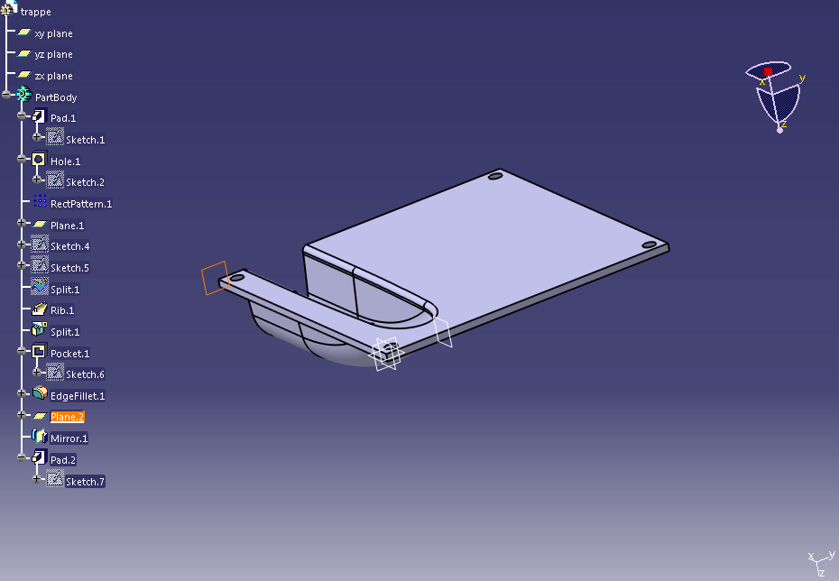
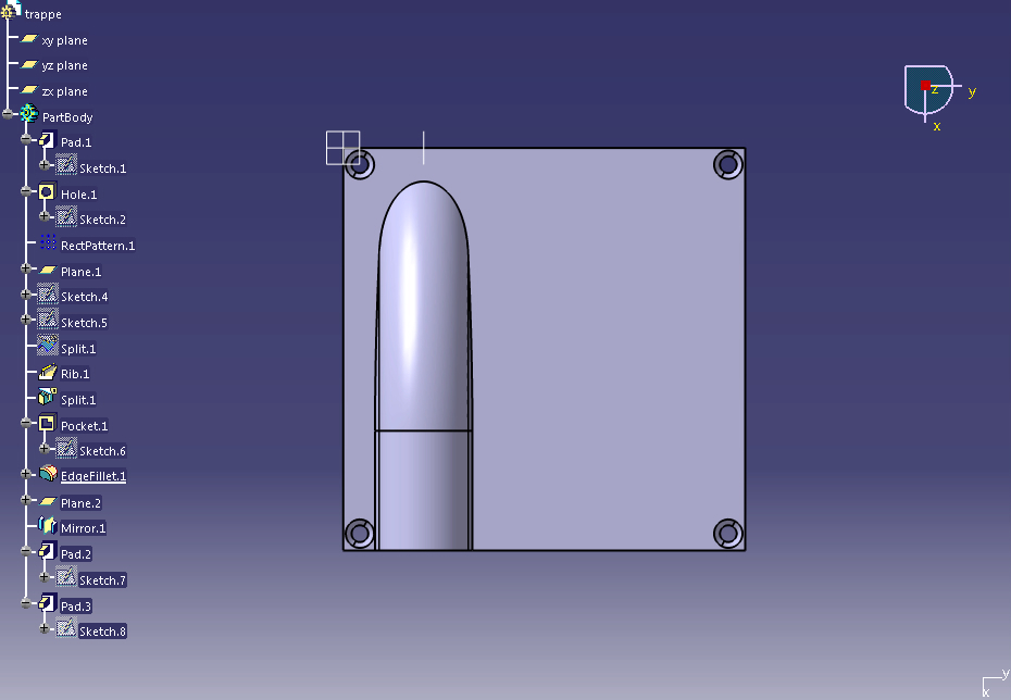
The aluminum mold will be CNC cut tomorrow. I should have the first prototypes by the end of the week.
The aluminum mold will be CNC cut tomorrow. I should have the first prototypes by the end of the week.
12-02-2013 | 09:59 AM
#23
Thread Starter
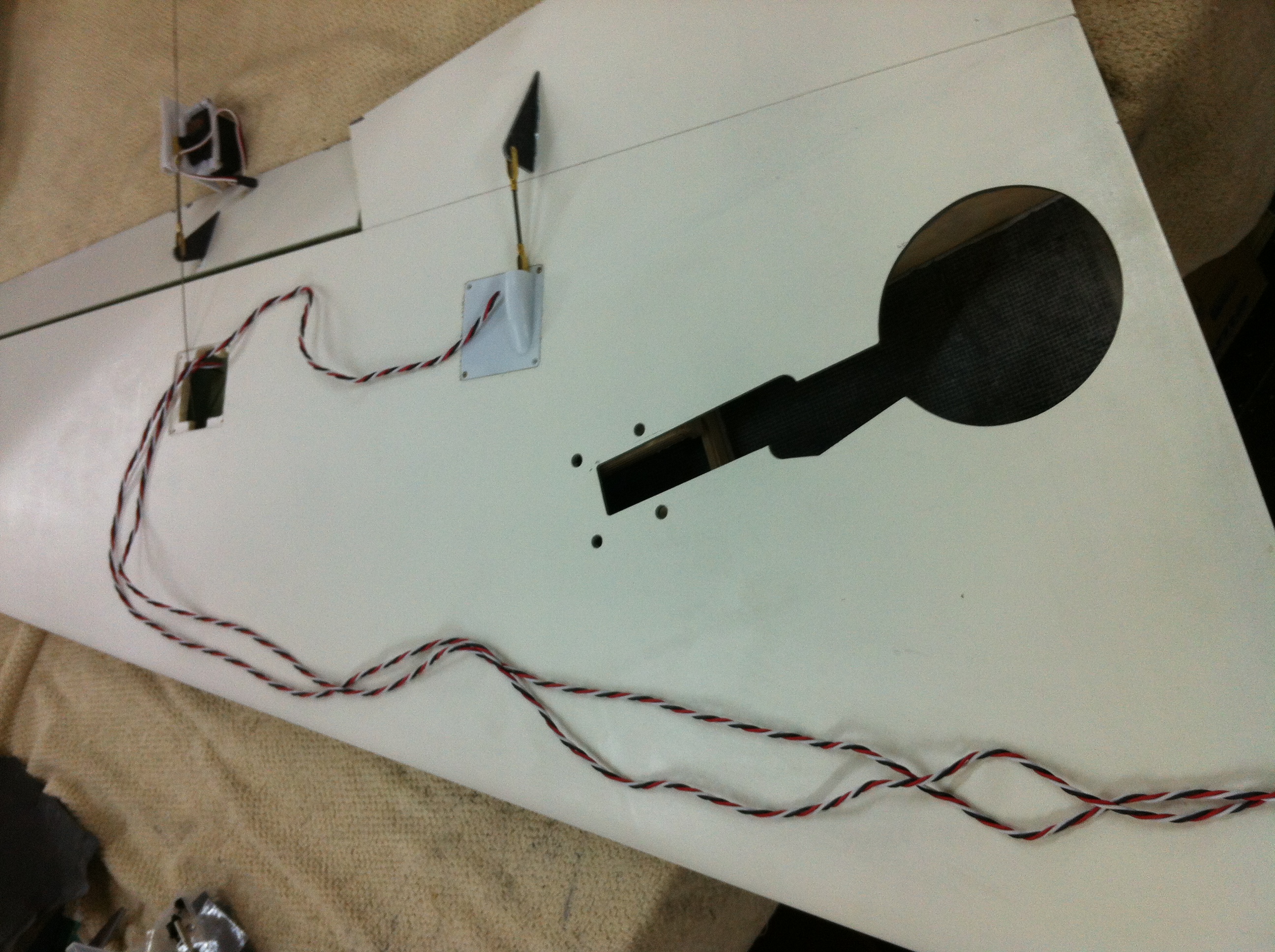
I am working on the Diamond loom right now.
It will be available as an option, just like for the Scorpion Mk II.
Emcotec EWC 6 and EWC 3 industrial quality plugs, MIL spec AWG 20 PTFE/ silver servo cables, MIL spec kevlar protection sleeve, Latched polarized servo plugs...
The picture below shows where the loom passes by in the wing.
It will be available as an option, just like for the Scorpion Mk II.
Emcotec EWC 6 and EWC 3 industrial quality plugs, MIL spec AWG 20 PTFE/ silver servo cables, MIL spec kevlar protection sleeve, Latched polarized servo plugs...
The picture below shows where the loom passes by in the wing.
Last edited by olnico; 12-12-2013 at 12:38 AM.

 12-12-2013 | 12:35 AM
#25
Thread Starter
A few pictures of the loom that will be offered as an option as part of Ultimate Jets custom loom services:
The part of the loom that is traveling into the engine bay ( elevators and rudder servos ) is made of our MIL spec PTFE/ silver AWG 22 servo cable. It is protected by a high temperature kevlar sleeve.

The part of the loom that is traveling into the engine bay ( elevators and rudder servos ) is made of our MIL spec PTFE/ silver AWG 22 servo cable. It is protected by a high temperature kevlar sleeve.

