


Hydraulic Retracts


 05-21-2014, 06:11 AM
#102

My Feedback: (1)
Join Date: Feb 2002
Location: private, UNITED KINGDOM
Posts: 3,672
Likes: 0
Received 26 Likes
on
16 Posts
I took a good look at the system in Mick's A-10 and T-33 last weekend and was impressed by the lovely action of the system.
Wonder if people have any views about what is the smallest size of jet model this is worth installing into, or is it simply "if you can fit the tank, pumps etc into the space, it's worth considering"
Can someone explain how any small air bubbles from the wing self-sealing disconnects are removed from the system? I understand that if the cylinder has more volume than the pipe then on the first cycle the line flowing back to the main tank will blow the bubble back there. However the line flowing to the retract will take the bubble to the cylinder where it will rise to the top and not be removed through a centrally mounted nipple on the next cycle? Or have I misunderstood something?
05-21-2014, 07:26 AM
#104
My Feedback: (11)
Join Date: Sep 2010
Location: marina del rey, CA
Posts: 199
Likes: 0
Received 0 Likes
on
0 Posts
I have played with my system quite a lot and can tell you that bubbles do not matter, huge pockets of air will affect the smoothness of the system but the retracts will still operate, at the pressure were dealing with air compression doesn't matter.
just realize that they system on hydraulics is operating at about 150-180 psi so if it would move with a traditional setup it will with this regardless of bubbles
i think you can put it in anything that can accommodate the extra hardware
just realize that they system on hydraulics is operating at about 150-180 psi so if it would move with a traditional setup it will with this regardless of bubbles
i think you can put it in anything that can accommodate the extra hardware
06-06-2014, 03:15 PM
#105

My Feedback: (49)
Join Date: Apr 2002
Location: SANTA ANA, CA
Posts: 2,182
Likes: 0
Received 0 Likes
on
0 Posts
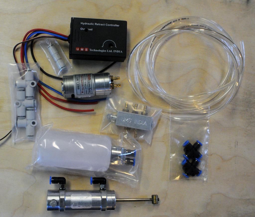
Here's a photo of the UMS system, with a couple of additions. The UMS was available configured for two gear. To convert to three gear requires two X festo fittings I ordered from Todd at Dream works.
The retract cylinder at the bottom is for a Century jet 1/6.75 F-18 SuperHornet. The Festo fittings were also obtained from Todd. They are 5mm thread for 4mm tubing. The cylinder originally is equipped with the standard brass nipple for 3mm tubing. The clear tube is provided by UMS and states on the tube that it is good to 10 bar 150 psi. From responses on this thread I will most likely use it for fuel tubing instead. If anyone in the US has already ordered a 50 ft roll of the Pan R tube and would like to sell some, please let me know. Otherwise I will soon be ordering a roll myself. I ordered two of the UMS sets, as I have the Century Jet F-18, as well as a Yellow 1/7 F-18C I am planning to convert this summer.
David S
06-08-2014, 10:47 PM
#106
Junior Member
Join Date: Jan 2005
Location: Liverpool, UNITED KINGDOM
Posts: 5
Likes: 0
Received 0 Likes
on
0 Posts
Hi All,
I thought I would share my take on trying to get the UMS system working on my large scale Lancaster project - http://www.rcgroups.com/forums/showthread.php?t=1918147
I gave up on trying to achieve the movement I wanted with Pneumatic systems and after reading this thread decided to try the UMS kit. Out of the box the concept worked really well but try as I could I just could not get the controller to work how I wanted, may be it was something in my design for the retracts but it resulted in the motor running on and getting incredibly hot
So I decided to take a different approach and use a Picaxe 08M2 servo driver board to time the sequence rather than measure pressure or current overload. This drives a BattleSwitch which turns the motor on and off. I wrote a simple programme that is designed to stop the gear actuating when the RX is first powered on and as the 08M2 board has a couple more servo outputs it controls the landing light retraction and illumination sequence. The sequence retracts or lowers the gear then runs the pump a few times for a short period to build up pressure in the system
I also used a PWM motor controller to slow the motor down but help to maintain its torque. This together with a couple of collets to restrict flow on one wheel has given me the scale movement I wanted
A little more work to do yet but pleased with the results so far and now the motor runs cold
https://www.youtube.com/watch?v=XE4TzZWBW_s


The only issue I have with the UMS kit is a leak from the spindle on the valve, I think this was caused by mounting the valve on the board at the same level as the servo which was pulling the spindle upwards at an angle, mounting the valve in the same plane as the pivot point on the servo arm seems to have stopped the leak but I have ordered a new valve anyway
Ken
I thought I would share my take on trying to get the UMS system working on my large scale Lancaster project - http://www.rcgroups.com/forums/showthread.php?t=1918147
I gave up on trying to achieve the movement I wanted with Pneumatic systems and after reading this thread decided to try the UMS kit. Out of the box the concept worked really well but try as I could I just could not get the controller to work how I wanted, may be it was something in my design for the retracts but it resulted in the motor running on and getting incredibly hot
So I decided to take a different approach and use a Picaxe 08M2 servo driver board to time the sequence rather than measure pressure or current overload. This drives a BattleSwitch which turns the motor on and off. I wrote a simple programme that is designed to stop the gear actuating when the RX is first powered on and as the 08M2 board has a couple more servo outputs it controls the landing light retraction and illumination sequence. The sequence retracts or lowers the gear then runs the pump a few times for a short period to build up pressure in the system
I also used a PWM motor controller to slow the motor down but help to maintain its torque. This together with a couple of collets to restrict flow on one wheel has given me the scale movement I wanted
A little more work to do yet but pleased with the results so far and now the motor runs cold
https://www.youtube.com/watch?v=XE4TzZWBW_s
The only issue I have with the UMS kit is a leak from the spindle on the valve, I think this was caused by mounting the valve on the board at the same level as the servo which was pulling the spindle upwards at an angle, mounting the valve in the same plane as the pivot point on the servo arm seems to have stopped the leak but I have ordered a new valve anyway
Ken
Last edited by heli_madken; 06-08-2014 at 10:52 PM.
06-08-2014, 11:53 PM
#107
Thread Starter
Join Date: Jul 2006
Location: Norfolk , UNITED KINGDOM
Posts: 1,409
Likes: 0
Received 0 Likes
on
0 Posts
Ken
Nice to see yet another way of getting the retracts to work. As you say the UMS electronics box makes the pump run hot and best avoided.
John
Nice to see yet another way of getting the retracts to work. As you say the UMS electronics box makes the pump run hot and best avoided.
John
06-09-2014, 12:13 AM
#108
My Feedback: (11)
Join Date: Sep 2010
Location: marina del rey, CA
Posts: 199
Likes: 0
Received 0 Likes
on
0 Posts
the ums box works fine as long as your system is not to restrictive and your hoses don't have the ability to expand to much, the system works by measuring load so if you have a restrictive system it will take a long time for the load to reach a point where it triggers the controller.
I found this when I was experimenting, with 3mm line the pump would get really hot because it would take a long time to actuate the gear and would run for a good time afterwards, presumably while the lines were all expanding and the pressure was equalizing everywhere, but as soon as everything was on 4mm line all is perfect now the gear move and stop the pump runs for a further few seconds then shuts off, every time!
I found this when I was experimenting, with 3mm line the pump would get really hot because it would take a long time to actuate the gear and would run for a good time afterwards, presumably while the lines were all expanding and the pressure was equalizing everywhere, but as soon as everything was on 4mm line all is perfect now the gear move and stop the pump runs for a further few seconds then shuts off, every time!
06-09-2014, 12:45 AM
#109
Junior Member
Join Date: Jan 2005
Location: Liverpool, UNITED KINGDOM
Posts: 5
Likes: 0
Received 0 Likes
on
0 Posts
Cheers, I am sure it is my setup that is to blame for the controller not working, apart from anything else its complexity is making it very difficult to get all air out of the system
One advantage I guess I do have is in the event of a leak the timed system isn't going to continue running the pump emptying the reservoir of oil all over my plane
One advantage I guess I do have is in the event of a leak the timed system isn't going to continue running the pump emptying the reservoir of oil all over my plane
05-21-2015, 04:25 AM
#110
Junior Member
Join Date: Jan 2005
Location: Liverpool, UNITED KINGDOM
Posts: 5
Likes: 0
Received 0 Likes
on
0 Posts
Hi everyone just resurrecting this thread, just a question, I notice that over a period of time I lose pressure in the system resulting in the gear slowly dropping, I imagine that I need the one way valves discussed earlier in the thread to prevent this but I am not clear where these would be fitted within the system, can anyone help with an explanation? Ken
05-21-2015, 04:41 AM
#111

The best thing to do is run a manifold that keeps constant pressure. The ones people on here use are some type of air cylinder with a spring inside and once the pressure hits a certain psi or over takes the spring and pushes the cylinder shaft out and contacts a simple switch to shut the motor off.
05-21-2015, 07:52 AM
#112
Thread Starter
Join Date: Jul 2006
Location: Norfolk , UNITED KINGDOM
Posts: 1,409
Likes: 0
Received 0 Likes
on
0 Posts
Hi everyone just resurrecting this thread, just a question, I notice that over a period of time I lose pressure in the system resulting in the gear slowly dropping, I imagine that I need the one way valves discussed earlier in the thread to prevent this but I am not clear where these would be fitted within the system, can anyone help with an explanation? Ken
The Festo one way valve goes between the pumped supply and the incoming line on the 5 port valve. This ensures that the fluid is under pressure and it is not possible to get the gear to go up with authority without it. I have a pressure relief valve between the pump and the Festo one way valve. There are 2 guys near me that have done hydraulic systems for their Mick Reeves Hunters using a time delay rather than pressure. This also works well and has been flown with this system a number of times.
John
