


US NAVY SeaDart F2Y (Flying boat) Build


 09-25-2019, 10:55 PM
#277

Thread Starter

Hi,
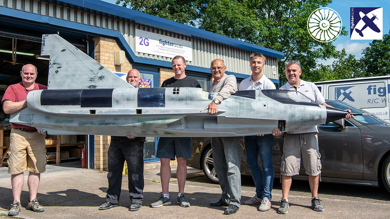
wow, it's been a while since I posted on here... where does the time go?
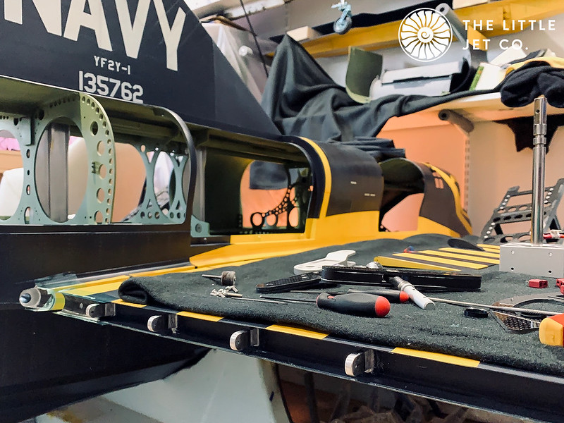
We're nearly finished the paint work, next week will see the clear go on then its a matter of putting the electronics in. We've got a lot of other stuff going on so its all a massive juggling act at the moment and a broken wrist isn't helping.
This is the fuselage after all the paint prep, nearly ready for the colour.
 <script async src="//embedr.flickr.com/assets/client-code.js" charset="utf-8"></script>
You can follow progress on our social media pages or our forum which you can get to through our website, it shows the build in detail. I'll post a few of the finished pictures on here when the time comes.
Cheers, Alex
wow, it's been a while since I posted on here... where does the time go?
We're nearly finished the paint work, next week will see the clear go on then its a matter of putting the electronics in. We've got a lot of other stuff going on so its all a massive juggling act at the moment and a broken wrist isn't helping.
This is the fuselage after all the paint prep, nearly ready for the colour.
<script async src="//embedr.flickr.com/assets/client-code.js" charset="utf-8"></script>You can follow progress on our social media pages or our forum which you can get to through our website, it shows the build in detail. I'll post a few of the finished pictures on here when the time comes.
Cheers, Alex
10-09-2019, 08:08 AM
#278
Thread Starter
A few more tweaks before the clear coat and then onto the equipment installation which will be done in and around our other work over the next few months.
 <script async src="//embedr.flickr.com/assets/client-code.js" charset="utf-8"></script>
<script async src="//embedr.flickr.com/assets/client-code.js" charset="utf-8"></script>


 06-04-2020, 01:29 AM
#282
Thread Starter
It has been a while� sorry!
I hope everyone has managed to stay safe and well during these last few months� strange times.
We have been busy working on multiple projects one of which is the SeaDart. We had planned to do the initial water tests in April but as it became clear this would not be possible we switched focus to other design work and projects that could be undertaken easily from home. I suspect we will be looking at the end of the summer before we can get the whole team together to begin testing. When we can the model is ready and waiting.
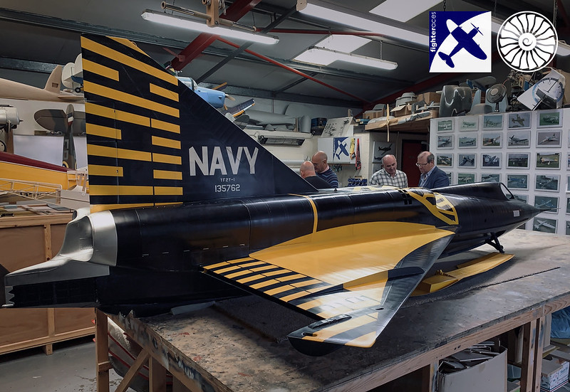
In the mean time I�ll start updating the thread to catch up to where we are. The last posts were at Fighteraces with them having just completed the paintwork.
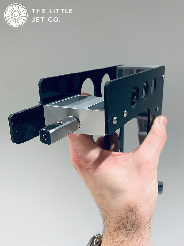
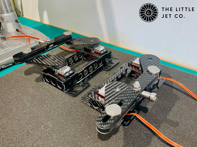
Once delivered to me the first thing to do was install the new elevon mechanism that was designed while it was in paint to replace the previous iteration which wasn�t up to the task. The new system has two large servos per elevon mounted near the CG. The elevons are actuated via a carbon tube and large drive horn. The bearing block and elevon drive is shown below.
 <script async src="//embedr.flickr.com/assets/client-code.js" charset="utf-8"></script>
 <script async src="//embedr.flickr.com/assets/client-code.js" charset="utf-8"></script>
Servo frame work that will be bonded into the fuselage just aft of the CG.
 <script async src="//embedr.flickr.com/assets/client-code.js" charset="utf-8"></script>
We are having to move considerable torque through this system so everything gets tied into the existing structure.
 <script async src="//embedr.flickr.com/assets/client-code.js" charset="utf-8"></script>
I hope everyone has managed to stay safe and well during these last few months� strange times.
We have been busy working on multiple projects one of which is the SeaDart. We had planned to do the initial water tests in April but as it became clear this would not be possible we switched focus to other design work and projects that could be undertaken easily from home. I suspect we will be looking at the end of the summer before we can get the whole team together to begin testing. When we can the model is ready and waiting.
In the mean time I�ll start updating the thread to catch up to where we are. The last posts were at Fighteraces with them having just completed the paintwork.
Once delivered to me the first thing to do was install the new elevon mechanism that was designed while it was in paint to replace the previous iteration which wasn�t up to the task. The new system has two large servos per elevon mounted near the CG. The elevons are actuated via a carbon tube and large drive horn. The bearing block and elevon drive is shown below.
<script async src="//embedr.flickr.com/assets/client-code.js" charset="utf-8"></script><script async src="//embedr.flickr.com/assets/client-code.js" charset="utf-8"></script>Servo frame work that will be bonded into the fuselage just aft of the CG.
<script async src="//embedr.flickr.com/assets/client-code.js" charset="utf-8"></script>We are having to move considerable torque through this system so everything gets tied into the existing structure.
<script async src="//embedr.flickr.com/assets/client-code.js" charset="utf-8"></script>Last edited by Alex48; 06-04-2020 at 02:15 AM. Reason: Issues with photos...
06-04-2020, 02:01 AM
#283
Thread Starter
With the rear elevon bearing block assembled I can now bond the elevon hinge supports in place. Both wings were bolted onto the fuselage. The elevon hinge supports installed in the elevon hanging off 2mm piano wire. These are bonded with Hysol into their slots in the wing. I then installed the bearing block structure using more Hysol and bolted the drive shaft to the elevon ensuring everything is in line while it cures.
 <script async src="//embedr.flickr.com/assets/client-code.js" charset="utf-8"></script>
 <script async src="//embedr.flickr.com/assets/client-code.js" charset="utf-8"></script>
 <script async src="//embedr.flickr.com/assets/client-code.js" charset="utf-8"></script>
The elevons will have the blue stripes added but this will be done after the elevon hinges have cured so we can get the masking in the correct position.
<script async src="//embedr.flickr.com/assets/client-code.js" charset="utf-8"></script><script async src="//embedr.flickr.com/assets/client-code.js" charset="utf-8"></script><script async src="//embedr.flickr.com/assets/client-code.js" charset="utf-8"></script>The elevons will have the blue stripes added but this will be done after the elevon hinges have cured so we can get the masking in the correct position.
06-04-2020, 02:04 AM
#284
Thread Starter
Now cured the main bearing blocks have been removed ready to paint the structure along with the servo frames situated about a meter forward of the bearing block structure.
 <script async src="//embedr.flickr.com/assets/client-code.js" charset="utf-8"></script>
This really should have been done before painting but I missed it along with a few other things. The corners are a little delicate and not supported as it's feathered carbon in these areas. If I don't reinforce it now it will no doubt get knocked at some point. I cut and bonded some carbon tube into the root trailing edges of fuselage and wing, I’ve only added this inboard of the first hinge as the elevon protects the rest.
 <script async src="//embedr.flickr.com/assets/client-code.js" charset="utf-8"></script>
 <script async src="//embedr.flickr.com/assets/client-code.js" charset="utf-8"></script>
<script async src="//embedr.flickr.com/assets/client-code.js" charset="utf-8"></script>This really should have been done before painting but I missed it along with a few other things. The corners are a little delicate and not supported as it's feathered carbon in these areas. If I don't reinforce it now it will no doubt get knocked at some point. I cut and bonded some carbon tube into the root trailing edges of fuselage and wing, I’ve only added this inboard of the first hinge as the elevon protects the rest.
<script async src="//embedr.flickr.com/assets/client-code.js" charset="utf-8"></script><script async src="//embedr.flickr.com/assets/client-code.js" charset="utf-8"></script>
06-08-2020, 12:23 AM
#286
Thread Starter
I hope everyone had a decent weekend.
With the support structure for the new elevon mechanism in place it was time to touch up the internal paintwork. I masked the entire fuselage section… just in case of any accidents!
 <script async src="//embedr.flickr.com/assets/client-code.js" charset="utf-8"></script>
I also reinforced the aft most former join with some carbon tape after filleting the angle and then applying with resin. (Before painting and while masked to avoid any resin fingerprints on the paintwork)
 <script async src="//embedr.flickr.com/assets/client-code.js" charset="utf-8"></script>
With the support structure for the new elevon mechanism in place it was time to touch up the internal paintwork. I masked the entire fuselage section… just in case of any accidents!
<script async src="//embedr.flickr.com/assets/client-code.js" charset="utf-8"></script>I also reinforced the aft most former join with some carbon tape after filleting the angle and then applying with resin. (Before painting and while masked to avoid any resin fingerprints on the paintwork)
<script async src="//embedr.flickr.com/assets/client-code.js" charset="utf-8"></script>
06-10-2020, 03:51 AM
#287
Thread Starter
With the internal painting completed I can finally get on with installing things for the last time. The rear elevon mechanism which includes the bearing blocks and actuating arm. The arm is installed with 6 capstan bolts to aid locking. I add shrink sleeve to the wire locks to avoid cutting my hands to shreds every time I need to get into the hull for the installation. I learnt the hard way!
 <script async src="//embedr.flickr.com/assets/client-code.js" charset="utf-8"></script>
The connection between the servos and rear mechanism is achieved with a 12mm carbon tube, aluminium inserts bonded and bolted in place with a left hand threaded M8 rod end.
 <script async src="//embedr.flickr.com/assets/client-code.js" charset="utf-8"></script>
<script async src="//embedr.flickr.com/assets/client-code.js" charset="utf-8"></script>The connection between the servos and rear mechanism is achieved with a 12mm carbon tube, aluminium inserts bonded and bolted in place with a left hand threaded M8 rod end.
<script async src="//embedr.flickr.com/assets/client-code.js" charset="utf-8"></script>
06-12-2020, 07:00 AM
#288
Thread Starter
On the servo side of things we decided to try the large Seiko servos, loads of torque but a little slow. They have a tie bar with a slot, this allows any disparity between the servo matching without loading the servo with them fighting each other. It also allows movement of the elevon with one servo failure. This at least gives you a fighting chance depending on where in its travel it fails… a difficult situation but better than no control at all!
 <script async src="//embedr.flickr.com/assets/client-code.js" charset="utf-8"></script>
 <script async src="//embedr.flickr.com/assets/client-code.js" charset="utf-8"></script>
I have also designed a bolt on tray so we can try some other servos and decide what is best.
 <script async src="//embedr.flickr.com/assets/client-code.js" charset="utf-8"></script>
Cheers, Alex
<script async src="//embedr.flickr.com/assets/client-code.js" charset="utf-8"></script><script async src="//embedr.flickr.com/assets/client-code.js" charset="utf-8"></script>I have also designed a bolt on tray so we can try some other servos and decide what is best.
<script async src="//embedr.flickr.com/assets/client-code.js" charset="utf-8"></script>Cheers, Alex
 07-07-2020, 02:25 AM
#291
Thread Starter
The Seadart was a concept for the US NAVY's mobile base idea and the new ability to launch supersonic aircraft from carriers was the final nail in its coffin. Born out of the Seadart testing came the F102, F106 and B58 using all the knowledge gained on the Delta wing during testing of the SeaDart. It's interesting looking at the F102 which is very much a land based SeaDart in many respects.
Where does the time go? With the kids now off for the summer I can spend my mornings working rather than home schooling, I hope the circumstances will allow for a return to school in September.
So, onwards with the build�
Our first thought with the elevon servos was torque so we decided to try the Tonegawa Seiko PS-050 servos which do provide plenty of torque although they lack speed.
A video of the servos operating.
They are slow as expected but also give feedback when the elevon is moved down and unexpectedly they appear rather notchy. They don't work well with the gyro due to the above. They also require a separate power supply and BEC increasing the weight of the model by 2 kgs. We decided not to use these and go with another solution. Dave Wilshere did warn that we might encounter problems but sometimes you just need to see for yourself. They won�t be wasted as we have a few projects in the works where these will be appropriate.
A video showing the Tonegawa servos operating the left elevon.
The next set of servos to try are the MKS HBL 388.
 <script async src="//embedr.flickr.com/assets/client-code.js" charset="utf-8"></script>
 07-07-2020, 01:35 PM
#294
Been using the Hitec HS-1005SGT for years on large scale UAV prototyping and they also come in a waterproof version, HS-1100WP.
https://hitecrcd.com/products/servos...000sgt/product
https://hitecrcd.com/products/servos...1100wp/product
You can also go to the commercial/industrial side of hitec https://hitecnology.hitecrcd.com/actuators they also have many different actuators as well, with very high outputs and different servo protocols.
Regards,
Last edited by Halcyon66; 07-07-2020 at 01:39 PM.
07-08-2020, 11:22 AM
#295
I’m sorry, I tested Hitec servos over more than 25 years, fed back comments and I have never found one servo in the range that impressed me. They don’t seem to fail, but they are not accurate and have the worst centring of any servo range I have ever come across. I’ve proved time and time again to doubters who think their Hitec servos are good, then they change a set up model to ( mainly JR in the day) and cannot believe the difference.
My regular comment as being fit for boats wouldn’t count on this occasion....
My regular comment as being fit for boats wouldn’t count on this occasion....
07-08-2020, 11:41 AM
#296
Each to their own.
Regards,
Regards,
07-08-2020, 11:51 AM
#297
Yep, just what I found. I worked very closely with one of the European distributors where my father was a 40 year+ partner in their company and we did not see an improvement in more than 15 years development...and that told me it would never happen.
07-08-2020, 12:11 PM
#298
So you have used the HS-1005SGT servos and had issues with them?
Regards,
Regards,
08-05-2020, 01:20 AM
#299
Thread Starter
Hi Guys,
I decided to try MKS mainly because it's a brand I have experience with and the specification was within what we had calculated so thought I'd give them a go. I designed the servo trays to be removable so its very easy to try differing brands and specifications if these prove to be problematic.
Flight loads aren't really the problem... I'm interested to see how they react to the elevon hitting the water during our water based testing. Testing is booked for early September as long as nothing changes with the current travel restrictions. fingers crossed! Notice also that I have added internal lights within the hull. It's such a big area that for maintenance this seemed like a good idea, we also need to check for any water ingress using a borescope between runs and the lighting should help.
We've replaced the Tonegawa Seiko PS-050 servos with four MKS HBL 388. These give 68kg/cm (944 oz/in) at 8.4 volts and a speed of 0.14s/60degrees.
A short video showing the elevon, and mechanism.
These worked well so we will see how they perform during the water based testing.
Last edited by Alex48; 08-05-2020 at 01:26 AM.
08-06-2020, 12:05 AM
#300
Thread Starter
The ski retraction. This has accounted for around 75% of the total design and development time on this project, Although initially it doesnt look that bad when you delve into the mechanism it becomes a geometric nightmare of epic proportions! I nearly lost my sanity more than once trying to get this to work!!
The purpose is to install only what is required initially to allow the ski retraction to actuate. We still don’t know how successful the ski retraction will be and with this part of the project taking a high proportion of the entire design and manufacture time I’m nervous that it won’t work…. Very nervous…
The first task was to dry fit all the formers and do the inevitable fettling to get them all to fit snugly in place. I’m primarily concerned with the first two formers in the aft section. These were fitted with the carbon ski wells in place. In conjunction with the keel beam slots, moulded return of the ski wells and formers including the main pivot block it all essentially self jigs into place. I bonded the first former and ski wells into place but left the main pivot block and second former which takes the load from the skis as I’m unsure if this part will require a re-design if the skis don’t retract.
 <script async src="//embedr.flickr.com/assets/client-code.js" charset="utf-8"></script>
I’m now at a stage where I can fit the prototype parts of the ski mechanisms and see if the skis will push up into place by hand. It’s a different matter to actuate it prototypically but at least I can see if the mechanism folds away as designed and the ski seats correctly on the side of the fuselage.
 <script async src="//embedr.flickr.com/assets/client-code.js" charset="utf-8"></script>
Did I mention earlyier I was nervous? This is where all my years of being around aircraft, models, engineering, all my academic and practical experience in aerospace for the last 30 years was bundled together and drop kicked out of my brain…
In my excitement on receiving the machined aluminium pivot block and stainless steel pivot pins I immediately installed them without any lubrication, without even checking the machined parts or removing any burrs and not installing the PTFE bushings (these were the raw machined parts with no finish post applied) After about three turns the whole thing seized inside the pivot block. The next three days were spent trying to remove the pivot block without damaging the composite fuselage or stainless steel pivot pin. After much head banging and profanity the only option left to me was to cut the block out with an angle grinder sacrificing the machined parts in order to save the fuselage. I had to remove a 2 inch square section from the carbon ski well to allow the external part of the pivot arm to fit through the ski well. I then set about destroying the pivot block taking care not to damage any of the hull composite.
It would have been unfair and just not right on my client to have charged for any of this time or replacement parts so I was rather grumpy with myself to say the least at having lost an entire week due to not engaging my brain! I did, however, manage to remove the block without compromising the composite hull.
 <script async src="//embedr.flickr.com/assets/client-code.js" charset="utf-8"></script>
Another week past and the new replacement components arrived. These were then inspected, polished to the specified RA, bushings and O-rings installed, greased and finally installed into the pivot block. This of course is what I should have done the first time...Let us never mention this again!
I can now see if the ski would at least push into place. The below video shows my initial thoughts.
Yay… although actuating it on what is a very short moment is still making me nervous, less so than before though…
The purpose is to install only what is required initially to allow the ski retraction to actuate. We still don’t know how successful the ski retraction will be and with this part of the project taking a high proportion of the entire design and manufacture time I’m nervous that it won’t work…. Very nervous…
The first task was to dry fit all the formers and do the inevitable fettling to get them all to fit snugly in place. I’m primarily concerned with the first two formers in the aft section. These were fitted with the carbon ski wells in place. In conjunction with the keel beam slots, moulded return of the ski wells and formers including the main pivot block it all essentially self jigs into place. I bonded the first former and ski wells into place but left the main pivot block and second former which takes the load from the skis as I’m unsure if this part will require a re-design if the skis don’t retract.
<script async src="//embedr.flickr.com/assets/client-code.js" charset="utf-8"></script>I’m now at a stage where I can fit the prototype parts of the ski mechanisms and see if the skis will push up into place by hand. It’s a different matter to actuate it prototypically but at least I can see if the mechanism folds away as designed and the ski seats correctly on the side of the fuselage.
<script async src="//embedr.flickr.com/assets/client-code.js" charset="utf-8"></script>Did I mention earlyier I was nervous? This is where all my years of being around aircraft, models, engineering, all my academic and practical experience in aerospace for the last 30 years was bundled together and drop kicked out of my brain…
In my excitement on receiving the machined aluminium pivot block and stainless steel pivot pins I immediately installed them without any lubrication, without even checking the machined parts or removing any burrs and not installing the PTFE bushings (these were the raw machined parts with no finish post applied) After about three turns the whole thing seized inside the pivot block. The next three days were spent trying to remove the pivot block without damaging the composite fuselage or stainless steel pivot pin. After much head banging and profanity the only option left to me was to cut the block out with an angle grinder sacrificing the machined parts in order to save the fuselage. I had to remove a 2 inch square section from the carbon ski well to allow the external part of the pivot arm to fit through the ski well. I then set about destroying the pivot block taking care not to damage any of the hull composite.
It would have been unfair and just not right on my client to have charged for any of this time or replacement parts so I was rather grumpy with myself to say the least at having lost an entire week due to not engaging my brain! I did, however, manage to remove the block without compromising the composite hull.
<script async src="//embedr.flickr.com/assets/client-code.js" charset="utf-8"></script>Another week past and the new replacement components arrived. These were then inspected, polished to the specified RA, bushings and O-rings installed, greased and finally installed into the pivot block. This of course is what I should have done the first time...Let us never mention this again!
I can now see if the ski would at least push into place. The below video shows my initial thoughts.
Yay… although actuating it on what is a very short moment is still making me nervous, less so than before though…