


US NAVY SeaDart F2Y (Flying boat) Build
 10-28-2015, 09:56 AM
#76

Thread Starter

Hi Matt
The formers are all hand drawn with reference to 1/4 scale drawings and our research photos. All the internal formers will be designed in CAD once the pattern has been scanned. Its a bit backward but we felt this method would produce the best pattern taking into consideration the holes in our initial research.
The other two large scratch built jets we are working on are all designed in CAD from the start as we have far more information available to do this accurately.
Last edited by Alex48; 10-28-2015 at 10:12 AM.

 10-28-2015, 07:00 PM
#78

My Feedback: (6)
Alex
Sorry to stick my old nose in hear, but I have a flying friend who is now retired, but was into cad from along way back and have seen some of the finished work from the cad programs and drawings he did and for this old bugger it is truly amazing.
So keep doing your thing
Cheers Bob T
Sorry to stick my old nose in hear, but I have a flying friend who is now retired, but was into cad from along way back and have seen some of the finished work from the cad programs and drawings he did and for this old bugger it is truly amazing.
So keep doing your thing
Cheers Bob T
10-29-2015, 12:20 AM
#79
Thread Starter
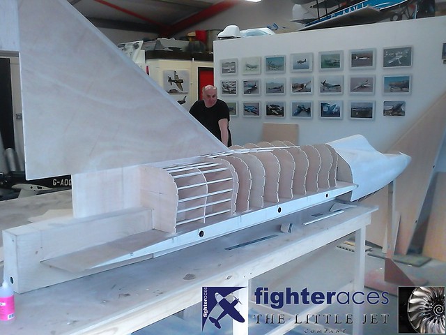
Hi Matt, hopefully this will clarify it but yes the guys did have to interpolate many of the formers. They had very accurate dimensions for the bounding box of the former as this could be taken from the drawings but all the curves had to be done by eye.
Thanks Bob
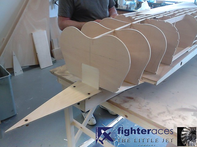
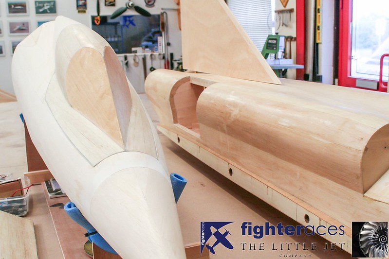
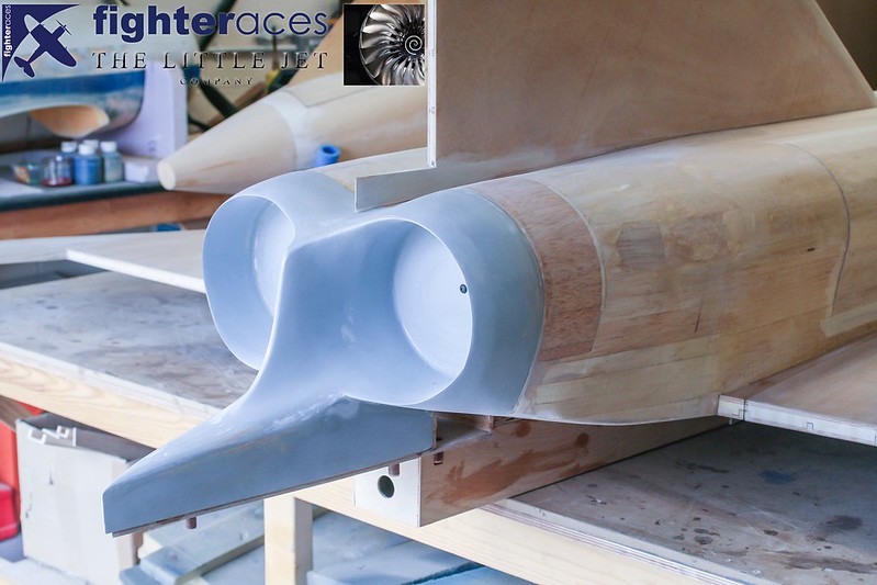
As per the forward fuselage, limited data was available for the rear fuselage sections. Of the 9 shown above, we only had drawings for 3 of them. Manual drawing techniques were used to generate the additional 6.........once in position, it was clear they were close but not perfect, so a little trimming & packing would been necessary to retain the smooth lines of the upper fuselage & air intake areas.
Phil Clark, FighterAces
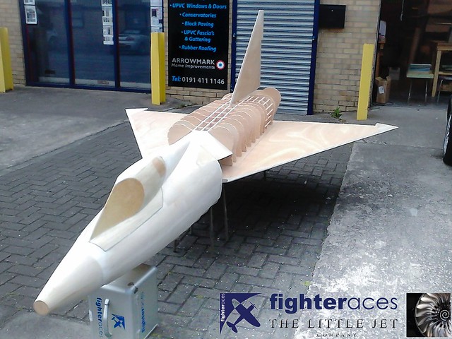
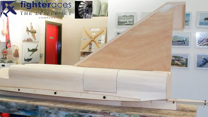
Another picture showing the work done on the fuselage. The bottom half of the fin has been built into the back of fuselage along with the centre sections of the wing which run through the large ply box that the structure fits onto.
 <script async src="//embedr.flickr.com/assets/client-code.js" charset="utf-8"></script>
Thanks Bob
As per the forward fuselage, limited data was available for the rear fuselage sections. Of the 9 shown above, we only had drawings for 3 of them. Manual drawing techniques were used to generate the additional 6.........once in position, it was clear they were close but not perfect, so a little trimming & packing would been necessary to retain the smooth lines of the upper fuselage & air intake areas.
Phil Clark, FighterAces
Another picture showing the work done on the fuselage. The bottom half of the fin has been built into the back of fuselage along with the centre sections of the wing which run through the large ply box that the structure fits onto.
<script async src="//embedr.flickr.com/assets/client-code.js" charset="utf-8"></script>
10-29-2015, 12:00 PM
#80
My Feedback: (6)
As per the forward fuselage, limited data was available for the rear fuselage sections. Of the 9 shown above, we only had drawings for 3 of them. Manual drawing techniques were used to generate the additional 6.........once in position, it was clear they were close but not perfect, so a little trimming & packing would been necessary to retain the smooth lines of the upper fuselage & air intake areas.
Phil Clark, FighterAces
Another picture showing the work done on the fuselage. The bottom half of the fin has been built into the back of fuselage along with the centre sections of the wing which run through the large ply box that the structure fits onto.
Alex more trivia, on the fwd fuse as memory serves me The cockpit was built as a separate water tight compartment/module and was to be ejected in an emergency, and did but do to the module landing upside down on the bay floor the rescue divers were not able to save the pilot.
From your pic's looks like you will end up with a vary close scale bird, will you be using Your cad system to design the innards placements and such ?
Cheers Bob T
10-30-2015, 12:45 AM
#81
Thread Starter
Yes all the innards on the flying model will be designed in CAD. We can do this as the pattern will be digitally scanned making the task much easier and quicker.
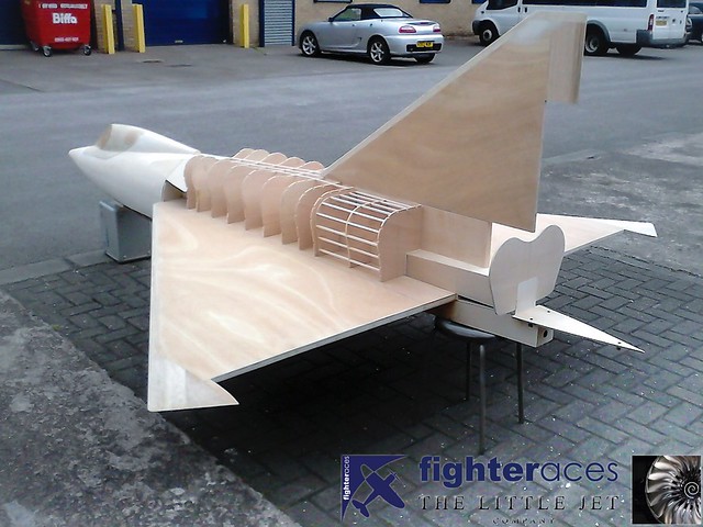
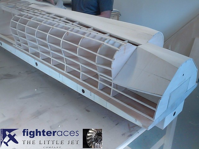
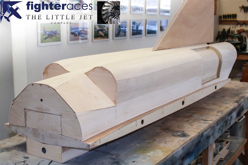
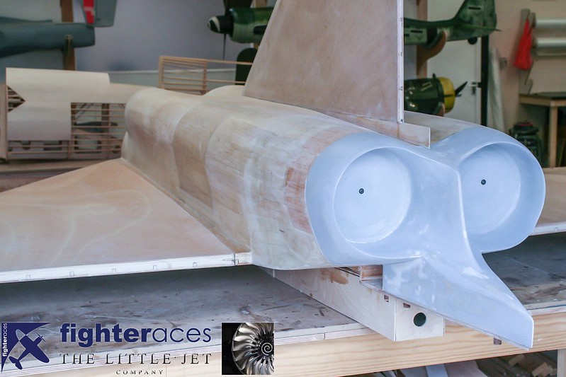
The stringered areas that are inset form the basis of the access hatches for the turbines........these match up with access panels on the full-size (the rear panel in the photo below). The panels themselves will be separate patterns allowing for 2 separate mouldings. The stringered sections are also separate structures (just pushed in position here) that will be bonded in once their surfaces are 100% finished which will allow us to face & finish the front & rear edges of the opening as well.
Phil Clark, FighterAces
 <script async src="//embedr.flickr.com/assets/client-code.js" charset="utf-8"></script>
The stringered areas that are inset form the basis of the access hatches for the turbines........these match up with access panels on the full-size (the rear panel in the photo below). The panels themselves will be separate patterns allowing for 2 separate mouldings. The stringered sections are also separate structures (just pushed in position here) that will be bonded in once their surfaces are 100% finished which will allow us to face & finish the front & rear edges of the opening as well.
Phil Clark, FighterAces
<script async src="//embedr.flickr.com/assets/client-code.js" charset="utf-8"></script>
10-30-2015, 07:58 AM
#82
Thread Starter
Now that some substance has been added to the rear section its starting to look very good. Much less imagibation needed this time. Superb work from FighterAces!
 <script async src="//embedr.flickr.com/assets/client-code.js" charset="utf-8"></script>
 <script async src="//embedr.flickr.com/assets/client-code.js" charset="utf-8"></script>v
 <script async src="//embedr.flickr.com/assets/client-code.js" charset="utf-8"></script>
<script async src="//embedr.flickr.com/assets/client-code.js" charset="utf-8"></script><script async src="//embedr.flickr.com/assets/client-code.js" charset="utf-8"></script>v<script async src="//embedr.flickr.com/assets/client-code.js" charset="utf-8"></script>
11-02-2015, 07:39 AM
#85
Thread Starter
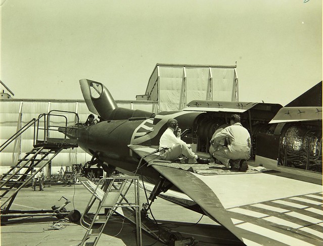
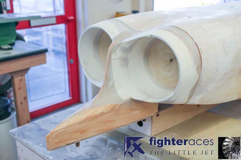
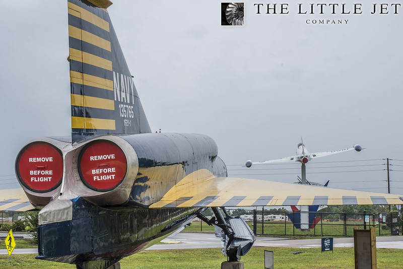
The rear of the aircraft is a real challenge. Our research photos from the Florida SeaDart and a few other 3 views from other sources have been used as a guide to produce the rear end of this SeaDart. nIt uses two Westinghouse J46 after burning engines which gives the rear a very different shape when compared to the first SeaDart.
 <script async src="//embedr.flickr.com/assets/client-code.js" charset="utf-8"></script>
<script async src="//embedr.flickr.com/assets/client-code.js" charset="utf-8"></script>
11-02-2015, 02:01 PM
#86
My Feedback: (6)
Hi Alex
You will have to forgive my foggy old memory, but the sea darts were built in Bay 3 of the experimental
shop and I don't remember A/B's on any of the sea dart engines, the J-57 used in the model 8/F102 did have them tho.
But I really like what you guys are doing.
Cheers Bob T
You will have to forgive my foggy old memory, but the sea darts were built in Bay 3 of the experimental
shop and I don't remember A/B's on any of the sea dart engines, the J-57 used in the model 8/F102 did have them tho.
But I really like what you guys are doing.
Cheers Bob T
11-02-2015, 11:27 PM
#87
Thread Starter
Hi Bob,
The first SeaDart built had Westinghouse J34's giving 3100lbs of thrust each. It was severely underpowered and never meant to have non after burning engines but the J46's were not available at the time of the first prototype. As soon as they were available they were installed into the second SeaDart giving almost twice the thrust which helped enormously. There is an excellent book by the test pilot BJ Long detailing the programme, might be worth a look if your interested in the development.
Cheers, Alex
11-04-2015, 02:32 AM
#89
Thread Starter
I didn't think that Bob... Its an interesting subject to model and we've spent years researching it but there is plenty that we don't know so keep the trivia coming 
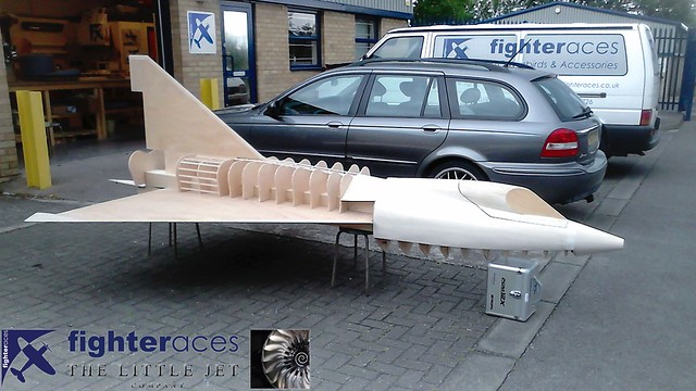
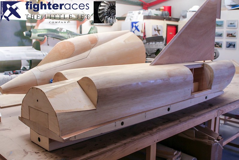
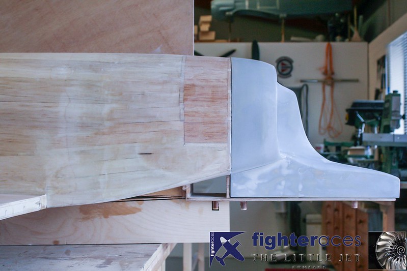
Sheeting the forward section of the rear fuselage...
A time consuming job ensuring all formers were level to ensure a smooth skin post sheeting as the shape change front to rear is very subtle. Phil Clark, FighterAces
 <script async src="//embedr.flickr.com/assets/client-code.js" charset="utf-8"></script>
 <script async src="//embedr.flickr.com/assets/client-code.js" charset="utf-8"></script>
Note here the port turbine hatch has also been built to fit the recess shown on the previous image. This is a seperate 1/2" thick pattern from 1/4" ply formers, 1/4 stringers & 1/8 balsa sheeting. Phil Clark, FighterAces
 <script async src="//embedr.flickr.com/assets/client-code.js" charset="utf-8"></script>
Sheeting the forward section of the rear fuselage...
A time consuming job ensuring all formers were level to ensure a smooth skin post sheeting as the shape change front to rear is very subtle. Phil Clark, FighterAces
<script async src="//embedr.flickr.com/assets/client-code.js" charset="utf-8"></script><script async src="//embedr.flickr.com/assets/client-code.js" charset="utf-8"></script>Note here the port turbine hatch has also been built to fit the recess shown on the previous image. This is a seperate 1/2" thick pattern from 1/4" ply formers, 1/4 stringers & 1/8 balsa sheeting. Phil Clark, FighterAces
<script async src="//embedr.flickr.com/assets/client-code.js" charset="utf-8"></script>
Last edited by Alex48; 11-05-2015 at 10:21 AM.
 11-04-2015, 03:17 PM
#93
Thread Starter
Thanks Mike, although I can't take credit for any of the physical workmanship on this SeaDart yet. All of what your seeing is done by the talanted guys at FighterAces. My turn will come next year when putting together the flying models. Cheers, Alex
11-05-2015, 10:24 AM
#94
Thread Starter
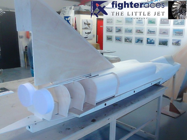
Rear section now sheeted up until the exhaust area which will be a seperate pattern.
 <script async src="//embedr.flickr.com/assets/client-code.js" charset="utf-8"></script>
 <script async src="//embedr.flickr.com/assets/client-code.js" charset="utf-8"></script>
<script async src="//embedr.flickr.com/assets/client-code.js" charset="utf-8"></script><script async src="//embedr.flickr.com/assets/client-code.js" charset="utf-8"></script>
11-06-2015, 02:46 AM
#95
Thread Starter
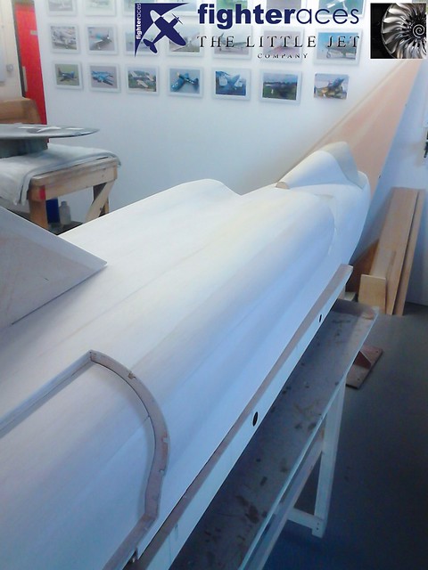
Rear top section is now glassed. The hull will be built once the CAD work is complete so the guys are using the time to do what glass work they can.
 <script async src="//embedr.flickr.com/assets/client-code.js" charset="utf-8"></script>
The rear section trimmed up ready for the initial surface prep.
 <script async src="//embedr.flickr.com/assets/client-code.js" charset="utf-8"></script>
Getting there
 <script async src="//embedr.flickr.com/assets/client-code.js" charset="utf-8"></script>
<script async src="//embedr.flickr.com/assets/client-code.js" charset="utf-8"></script>The rear section trimmed up ready for the initial surface prep.
<script async src="//embedr.flickr.com/assets/client-code.js" charset="utf-8"></script>Getting there
<script async src="//embedr.flickr.com/assets/client-code.js" charset="utf-8"></script>
11-06-2015, 08:51 AM
#96
My Feedback: (6)
Alex Things are looking great, and the workman ship is fantastic.
cheer Bob T
P/S t/t another old geezer that worked with me back in the day, and the engine bay that I remember was just the pogo stick engines prior to being mated to there gear boxes and the J- 57 for the model 8/102's, and from what he told me the SEA Dart engines were in the opposite side of the darts final assembly bay
11-06-2015, 11:56 PM
#97
Thread Starter
Hi Bob, would you be able to PM your email address? I'm currently involved in building a RC 1/6th scale Pogo and was wondering if you could shed some light on a few photos we have.
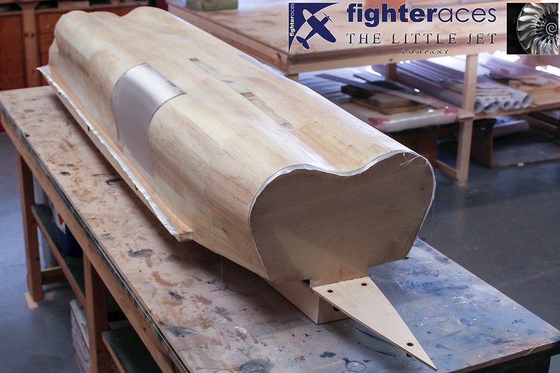
As per the wings, the fuselage has been glassed in heavy 4oz cloth to give a rock solid base to the pattern.......the whole upper rear fuselage being done in 1 piece (good game, good game!!!)
Also not the 'patchwork' at the very rear of the fuselage ahead of the jet pipe area in photo #2. We said this area was a problem due to the lack of documantation and this patchwork of balsa is the result......I'll happily admit the final shape was actually Mk.3 of the rear end as there was a lot of packing and sanding involved to achieve a shape we were finally happy with.
Phil Clark, FighterAces
11-07-2015, 12:12 AM
#98
Thread Starter
The exhaust pattern is being sculpted by John from FighterAces who's just retired from a career in TV & film set/prop design. Sculpting something from a load of photos is a perfect task for him. This has seen a few iterations but its finally getting to a shape that we are happy with. The rear end has also been slightly re modelled. We always knew the back would be time consuming due to the lack of any accurate drawings but FighterAces are doing a great job with the all our research photos to accurately recreate this part of the model.
The exhaust pattern around two thirds complete.
 <script async src="//embedr.flickr.com/assets/client-code.js" charset="utf-8"></script>
 <script async src="//embedr.flickr.com/assets/client-code.js" charset="utf-8"></script>
 <script async src="//embedr.flickr.com/assets/client-code.js" charset="utf-8"></script>
 <script async src="//embedr.flickr.com/assets/client-code.js" charset="utf-8"></script>
This has seen a few iterations but its finally getting to a shape that we are happy with. The rear end has also been slightly re modelled. We always knew the back would be time consuming due to the lack of any accurate drawings but FighterAces are doing a great job with the all our research photos to accurately recreate this part of the model.The exhaust pattern around two thirds complete.
<script async src="//embedr.flickr.com/assets/client-code.js" charset="utf-8"></script><script async src="//embedr.flickr.com/assets/client-code.js" charset="utf-8"></script><script async src="//embedr.flickr.com/assets/client-code.js" charset="utf-8"></script><script async src="//embedr.flickr.com/assets/client-code.js" charset="utf-8"></script>
Last edited by Alex48; 11-07-2015 at 01:11 AM.
11-08-2015, 12:02 PM
#99
Thread Starter
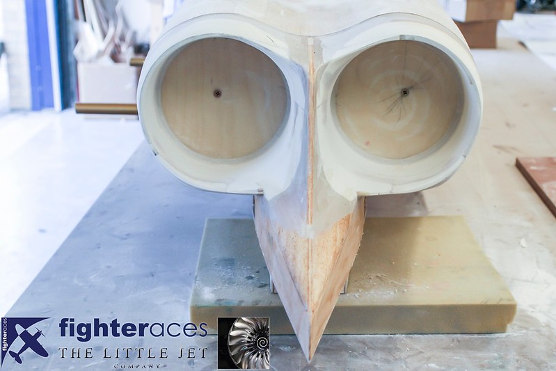
To say that this small part is by far the most complex part of the patter is an understatement.....there isn't a straight line in it!!!! Built from a mix of liteply, balsa block, light grade Chemiwood (Necuron 301) with a healthy dose of car body filler, this in itself represents a good couple of days work.
Phil Clark, FighterAces
The hull will be built once the CAD work is complete so with the supper surface fully sheeted, we made a start on the upper surface glassing work.
As per the wings, the fuselage has been glassed in heavy 4oz cloth to give a rock solid base to the pattern.......the whole upper rear fuselage being done in 1 piece (good game, good game!!!)
Also not the 'patchwork' at the very rear of the fuselage ahead of the jet pipe area in photo #2. We said this area was a problem due to the lack of documentation and this patchwork of balsa is the result......I'll happily admit the final shape was actually Mk.3 of the rear end as there was a lot of packing and sanding involved to achieve a shape we were finally happy with.
Phil Clark, FighterAces
Phil Clark, FighterAces
The hull will be built once the CAD work is complete so with the supper surface fully sheeted, we made a start on the upper surface glassing work.
As per the wings, the fuselage has been glassed in heavy 4oz cloth to give a rock solid base to the pattern.......the whole upper rear fuselage being done in 1 piece (good game, good game!!!)
Also not the 'patchwork' at the very rear of the fuselage ahead of the jet pipe area in photo #2. We said this area was a problem due to the lack of documentation and this patchwork of balsa is the result......I'll happily admit the final shape was actually Mk.3 of the rear end as there was a lot of packing and sanding involved to achieve a shape we were finally happy with.
Phil Clark, FighterAces
11-08-2015, 12:08 PM
#100
Thread Starter
and this is the result... the fuselage is yet to be blended into the exhaust but its getting there.
 <script async src="//embedr.flickr.com/assets/client-code.js" charset="utf-8"></script>
 <script async src="//embedr.flickr.com/assets/client-code.js" charset="utf-8"></script>
A good picture showing the amount of effort thats gone into getting this bit right. Next is to prep the wings for final finishing and blend this into the fuselage.
 <script async src="//embedr.flickr.com/assets/client-code.js" charset="utf-8"></script>
<script async src="//embedr.flickr.com/assets/client-code.js" charset="utf-8"></script><script async src="//embedr.flickr.com/assets/client-code.js" charset="utf-8"></script>A good picture showing the amount of effort thats gone into getting this bit right. Next is to prep the wings for final finishing and blend this into the fuselage.
<script async src="//embedr.flickr.com/assets/client-code.js" charset="utf-8"></script>