


Xicoy - LG15 Gyro Controlled Brakes
 03-19-2019, 09:30 AM
#76

Thread Starter
The Castle BEC comes set at 5 VDC output. I have a Castle Link but it may not be a Version 3, which is the current version. I used the one I have now to set the ESC in my Blade 180 Heli. Did you get a Version 3 to change your output voltage? Or, I am wondering if my Castle Link will work. Got any idea on that?
Sorry for the slow reply here, I missed this post and just saw it today. I have an older Castle Link (4-5 years old) that I used to program these little BECs, but this past Fall I could not find it so I ordered a new Link (v3) so now I have two (one to use while I'm looking for the other one
 ) You should be able to use the Link you have to adjust the voltage. -Tom
 12-11-2019, 10:09 PM
#77

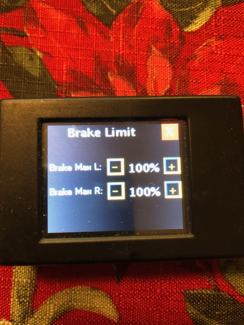
Here is what the brake limit page looks like, I have mine set to 100% for both. I use the mix in the radio to limit the overall brake force, you could limit it here instead.
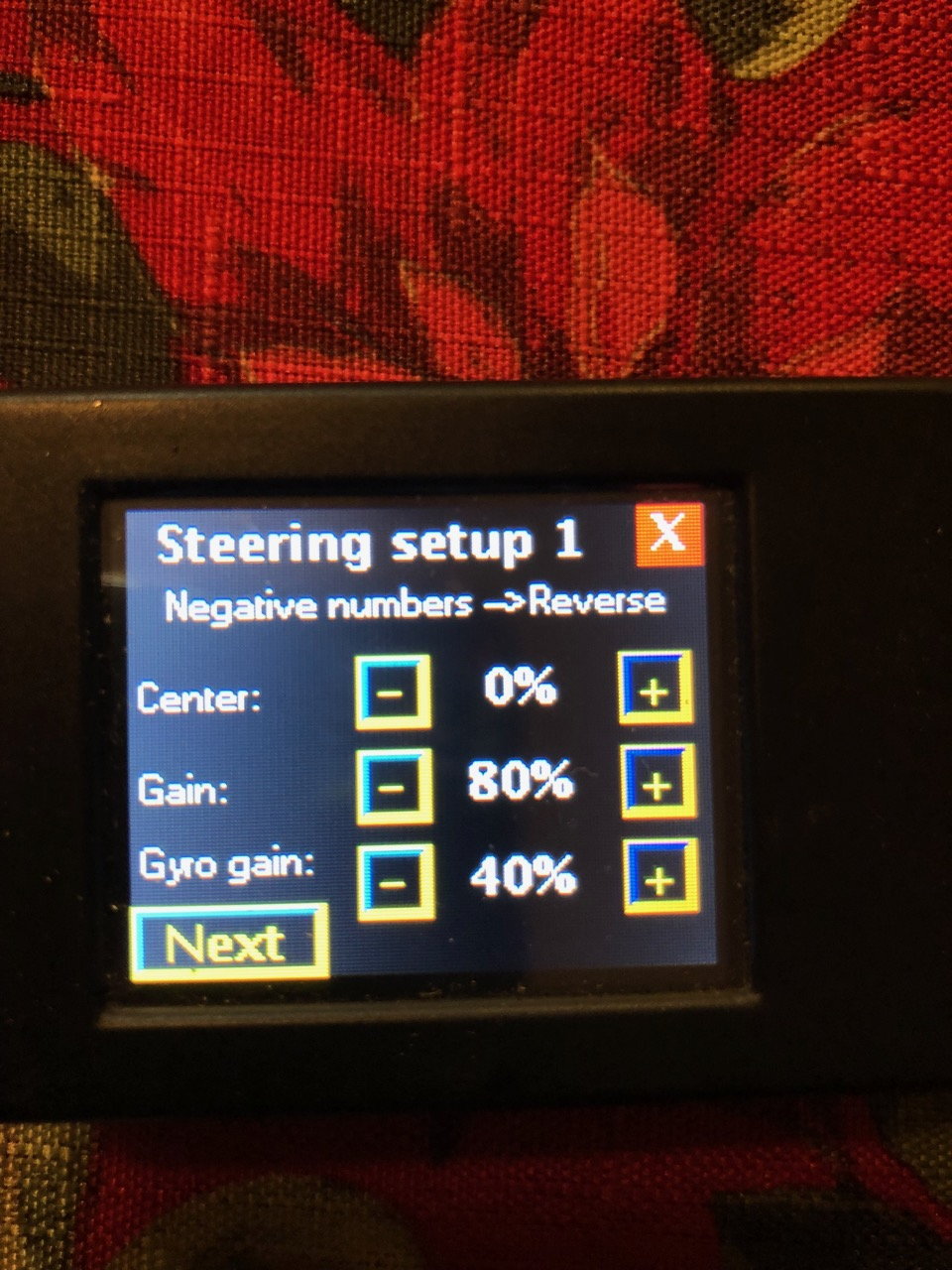
I don't remember the difference between Gain and Gyro Gain, will need to review the manual and update this post. However, these are my settings that work well.
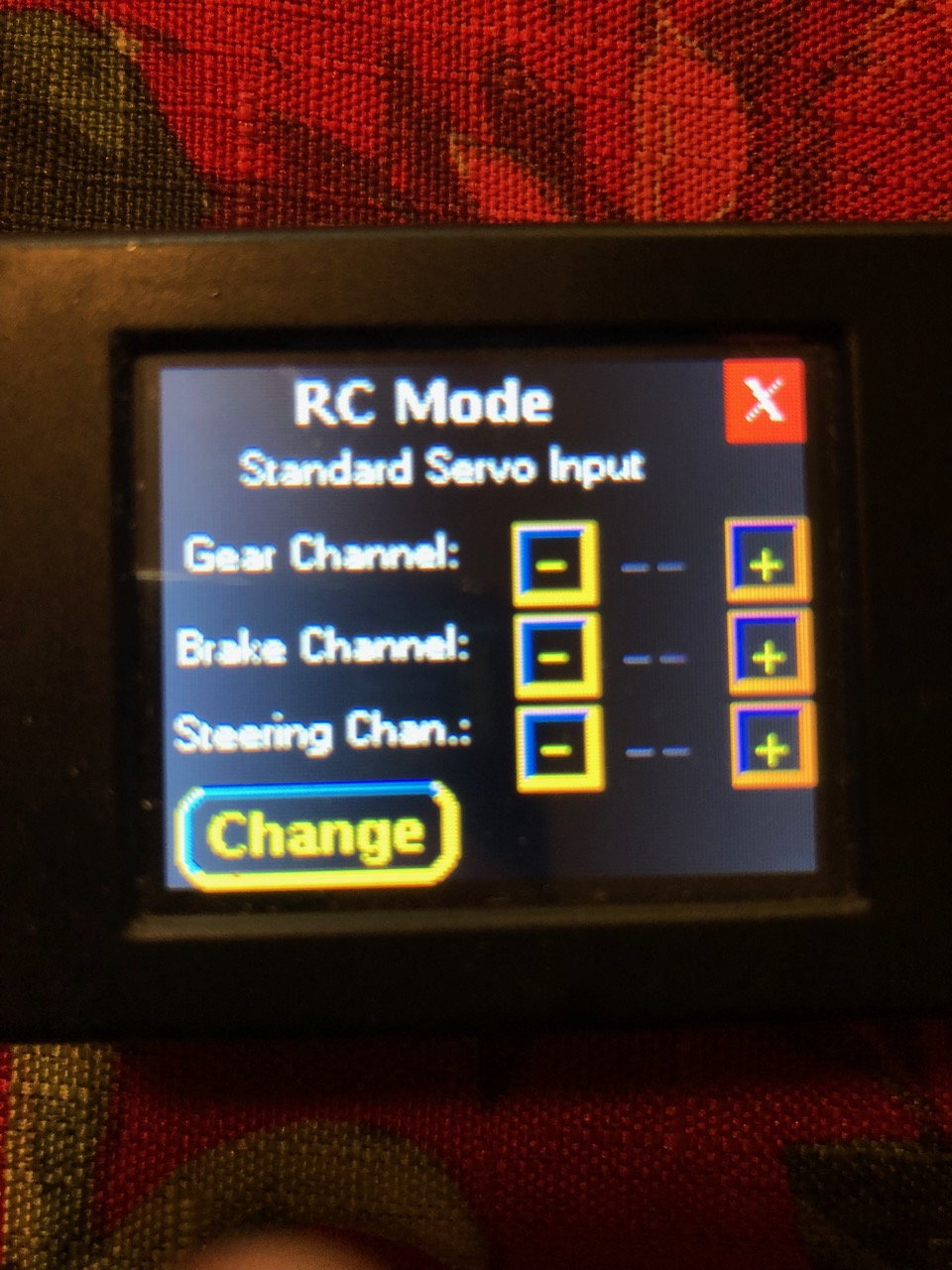
Click the Change button to select Jeti UDI, Futaba S-Bus etc.
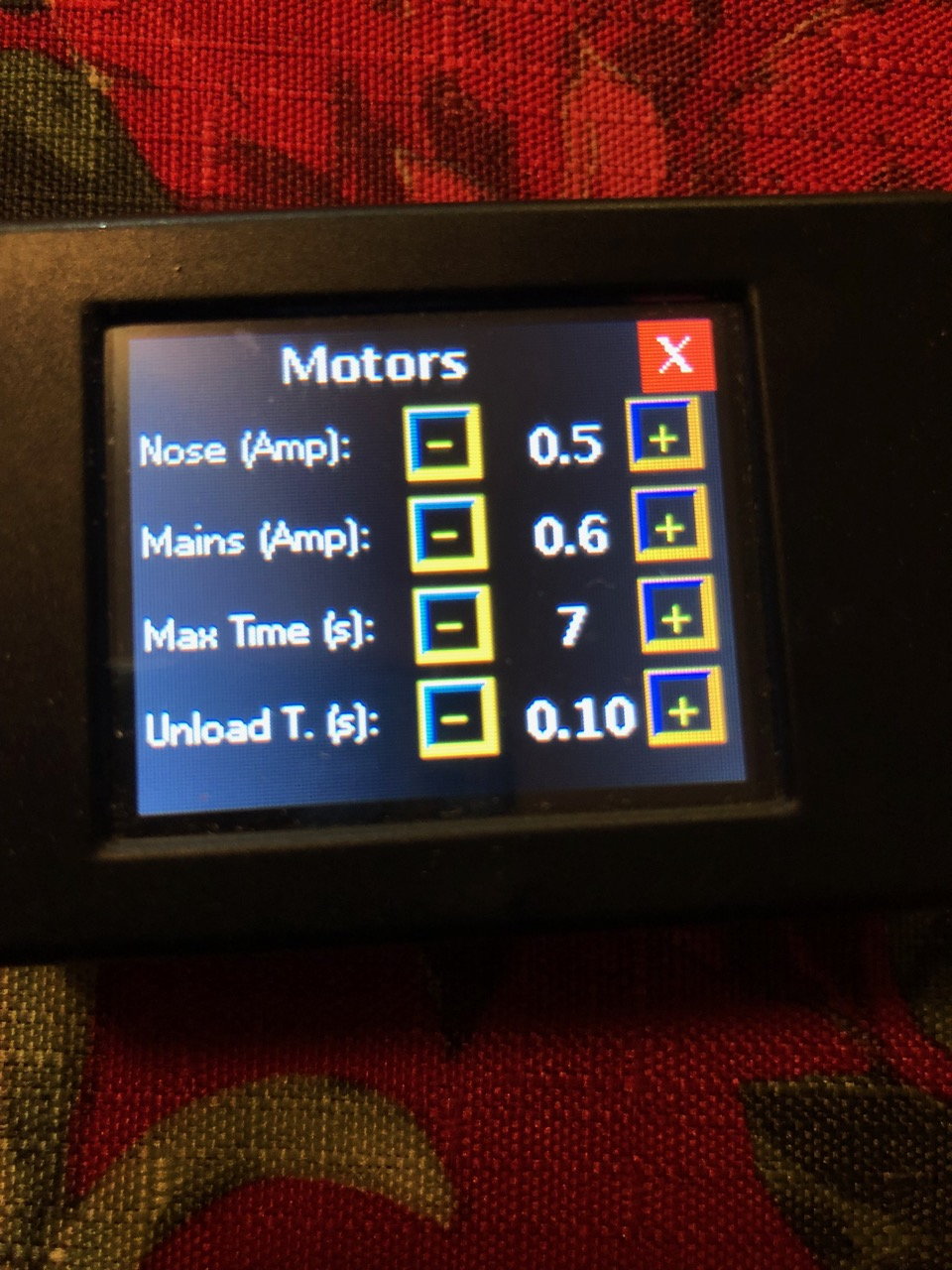
I recommend starting with .5 amps on the JP electric retracts, I had to bump up the mains to .6 to get them to retract consistently. Be very careful if you power this unit via 2SLipo as the JP Retract motors can only handle 7.5 volts, ask me how I know that! With 2SLipo I use a regulator set to 7.5v, another option is 2SLiFe, which does not require a regulator.
"Just talked to JP and their controllers DO NOT HAVE REGULATORS BUILT IN. Their gear motors operating voltage is 7.4 - 8.4V. The motors are stopped when a regulated amperage is met"
 12-12-2019, 04:38 AM
#78

Not sure if things have changed in the past year, but according to my JP gear controller that I received with my Rebel HOT that has JP gear pre-installed, it can accept 7.4-8.4 volts input, and I received this from Dirk at Pacific Jets in an email:
"Just talked to JP and their controllers DO NOT HAVE REGULATORS BUILT IN. Their gear motors operating voltage is 7.4 - 8.4V. The motors are stopped when a regulated amperage is met"
"Just talked to JP and their controllers DO NOT HAVE REGULATORS BUILT IN. Their gear motors operating voltage is 7.4 - 8.4V. The motors are stopped when a regulated amperage is met"
12-12-2019, 06:17 AM
#79

My Feedback: (53)

All electric retract....since they don�t have a micro switch to know when to switch the motor off, used a the amp as the factor, when the controller feel that amperage it stop the motor, then you always a small noise after....that�s to release the tension....to unload the motor...also setup in the controller.
 12-12-2019, 07:45 AM
#81
That's correct. JP is around 1 amp peak for shutoff, but I believe it's suggested to start around a half amp and work up from there.
add much as I know Dirk is reputable, I fear he may be mistaken on the jp voltage value. Luckily, I have a regulator handy that I can set to 6 or 7.4 volts.
add much as I know Dirk is reputable, I fear he may be mistaken on the jp voltage value. Luckily, I have a regulator handy that I can set to 6 or 7.4 volts.
12-12-2019, 08:16 AM
#82

Just FYI if you have a heavier gear the Xicoy gear controllers have a higher AMP version available upon request if need be. I will have to check on the LG15 but I know this to be fact for the 12/13 versions.
12-12-2019, 11:22 AM
#83
My JP Gear controller was regulated to 7.5 VDC output. While the Input could be as high as 8.4 VDC, the output always measured at 7.5 VDC. Unless JP changed something in the last two years, it should be the same. I measured mine just before I put in the LGC 15. My JP controller went in the trash a long time ago otherwise I would go check it again to make sure I remembered it correctly. But a good check for anyone would be to measure what you have on the bench before you install it. IMHO, that applies to any powered device, anytime something is changed.
12-12-2019, 03:25 PM
#84
Thread Starter

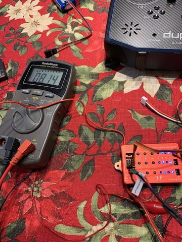
I cannot not say anything about any of the JP controllers that I don't own, however I own two of V-1 versions and when I put a volt meter on the retract connector and active the retracts the voltage output is 7.53v, this is with a fully charged 2S lipo connected (8.4v), therefore the controller is definitely limiting the voltage to the retract motor. Maybe there is no actual regulator built in, but the two units I have both limit the voltage to the retract motors at 7.53volts so something inside the JP controller is dropping the input voltage. I do have a third JP controller that is newer (A0802?) and it also limits the voltage, but it limits to 8.14v, which is still less than the 8.4v input from the 2S Lipo. These are facts, and nothing JP can say will change them (see the attached pictures).
Here is what I still have not figured out. I've owned and flown three minis (the first one is no longer with us, RIP
), I still fly the other two. All of them have the JP retracts. In my first mini, I installed an LG-15 after the first few flights, I adjusted the cutoff amperage to .5 AMPS and flew it about 30 flights with no retract issues. Long story short, I lost one mini and purchased two more. On the second mini I setup the LG-15 the same way I setup the LG-15 on the Mini #1, and while testing retracts during the build I burned up three motors (1 on the left side, two on the right). That's when I got suspicious and checked the output voltage on JP Controller and noticed it was 7.53v, the LG-15 was sending the full 8.4v to the retract motors, so I figured the retract motors were getting burned up because they could not handle the 8.4v. I verified this hypothesis by putting small regulator (limited to 7.5v) on the input side of the LG-15 and have flown my other two minis at least 100 times with only a single issue (later determined to be caused by a loose plug). So, my question is why did the retracts in mini #1 work perfectly without a regulator, where as the reracts on mini #2 burned up three motors? One explanation could be that the manufacturer changed up their materials or design after the original set of retracts were built, but who knows? One last thing, I connected an AMMETER in series with the retract motor and verified that the cutoff amperage was around .5 amps, so I'm pretty confident the motors did not burn up because the cutoff amperage was too high.I believe there are others who have also checked the voltage output on the these JP controllers and they have also reported a voltage of 7.5v, so I don't think I'm the only one.
12-12-2019, 03:28 PM
#85
Thread Starter
My JP Gear controller was regulated to 7.5 VDC output. While the Input could be as high as 8.4 VDC, the output always measured at 7.5 VDC. Unless JP changed something in the last two years, it should be the same. I measured mine just before I put in the LGC 15. My JP controller went in the trash a long time ago otherwise I would go check it again to make sure I remembered it correctly. But a good check for anyone would be to measure what you have on the bench before you install it. IMHO, that applies to any powered device, anytime something is changed.
 12-12-2019, 04:06 PM
#87
Thread Starter
12-12-2019, 06:44 PM
#89
How does it work? It works great. If the plane goes off course, the offending brake lets off and the other side adds braking power. You can actually see it visually on the controller's LEDs.
12-12-2019, 08:13 PM
#91
I cannot not say anything about any of the JP controllers that I don't own, however I own two of V-1 versions and when I put a volt meter on the retract connector and active the retracts the voltage output is 7.53v, this is with a fully charged 2S lipo connected (8.4v), therefore the controller is definitely limiting the voltage to the retract motor. Maybe there is no actual regulator built in, but the two units I have both limit the voltage to the retract motors at 7.53volts so something inside the JP controller is dropping the input voltage. I do have a third JP controller that is newer (A0802?) and it also limits the voltage, but it limits to 8.14v, which is still less than the 8.4v input from the 2S Lipo. These are facts, and nothing JP can say will change them (see the attached pictures).
Here is what I still have not figured out. I've owned and flown three minis (the first one is no longer with us, RIP
), I still fly the other two. All of them have the JP retracts. In my first mini, I installed an LG-15 after the first few flights, I adjusted the cutoff amperage to .5 AMPS and flew it about 30 flights with no retract issues. Long story short, I lost one mini and purchased two more. On the second mini I setup the LG-15 the same way I setup the LG-15 on the Mini #1, and while testing retracts during the build I burned up three motors (1 on the left side, two on the right). That's when I got suspicious and checked the output voltage on JP Controller and noticed it was 7.53v, the LG-15 was sending the full 8.4v to the retract motors, so I figured the retract motors were getting burned up because they could not handle the 8.4v. I verified this hypothesis by putting small regulator (limited to 7.5v) on the input side of the LG-15 and have flown my other two minis at least 100 times with only a single issue (later determined to be caused by a loose plug). So, my question is why did the retracts in mini #1 work perfectly without a regulator, where as the reracts on mini #2 burned up three motors? One explanation could be that the manufacturer changed up their materials or design after the original set of retracts were built, but who knows? One last thing, I connected an AMMETER in series with the retract motor and verified that the cutoff amperage was around .5 amps, so I'm pretty confident the motors did not burn up because the cutoff amperage was too high.I believe there are others who have also checked the voltage output on the these JP controllers and they have also reported a voltage of 7.5v, so I don't think I'm the only one.
In the interest of not burning up gear, I have a nice Hobbywing regulator sitting here that I can set to 7.4 volts, so that's what I'm doing.
Last edited by bodywerks; 12-12-2019 at 10:42 PM.
12-12-2019, 09:21 PM
#92
Thread Starter
12-13-2019, 06:50 AM
#93
Thread Starter
Thank you for this. Hard to argue with data. I would test my JP, but that stupid JST connector they use for power allows connectors to be installed backwards(ask me how I know).
In the interest of not burning up gear, I have a nice Hobbywing regulator sitting here that I can set to 7.4 volts, so that's what I'm doing.
In the interest of not burning up gear, I have a nice Hobbywing regulator sitting here that I can set to 7.4 volts, so that's what I'm doing.
12-13-2019, 08:26 AM
#95
My T-1 voltage is regulated to 7.5 VDC, At that voltage, I am limiting the LGC15's brake power output to ~ 60%. This is just shy of what is needed to lock the brakes up. The brakes will lock up at 80%. So limiting the voltage to 7.5 VDC will not prevent the brakes from locking up. You do not want the brakes to lock anyway! That is why you get all the adjustments.
As far as programming the LGC-15, you may want to consider googleing the manual and digging into it on the bench with the LGC 15 and gear sitting there. If you think you may need one, then you should be able to read it, versus having us waste out time recreating the manual. Right? The manual is out there on-line and its directions are fine. Once you do that and have specific questions, then it may be a great idea to post them here. Otherwise you may get some bum information and you waste a lot of time.
As far as programming the LGC-15, you may want to consider googleing the manual and digging into it on the bench with the LGC 15 and gear sitting there. If you think you may need one, then you should be able to read it, versus having us waste out time recreating the manual. Right? The manual is out there on-line and its directions are fine. Once you do that and have specific questions, then it may be a great idea to post them here. Otherwise you may get some bum information and you waste a lot of time.
12-13-2019, 08:38 AM
#96
Thread Starter
The only way I can think of to separate the brake power from the retract power is to use two different devices, i.e. use the LG-15 to control the brakes, and use the JP controller for the retracts. This is clearly not ideal, but technically possible.
12-13-2019, 01:15 PM
#98
Thread Starter
-Tom
12-13-2019, 06:08 PM
#99
I have JP gear/brakes. Do I need to switch the connectors to a 3-pin type and put the wires on the outer slots? The manual is clear as mud on this, and the device doesn't label the pin polarity like it does the servo in/outputs and power input. All it says is polarity doesn't matter, and just to make sure the gear position agrees with what the display says.
12-13-2019, 06:16 PM
#100
I have JP gear/brakes. Do I need to switch the connectors to a 3-pin type and put the wires on the outer slots? The manual is clear as mud on this, and the device doesn't label the pin polarity like it does the servo in/outputs and power input. All it says is polarity doesn't matter, and just to make sure the gear position agrees with what the display says.