


F 100 New Ride


The following users liked this post:
ifly3d (05-19-2020)

 05-19-2020, 05:18 AM
#6

My Feedback: (8)
A bit of trivia:
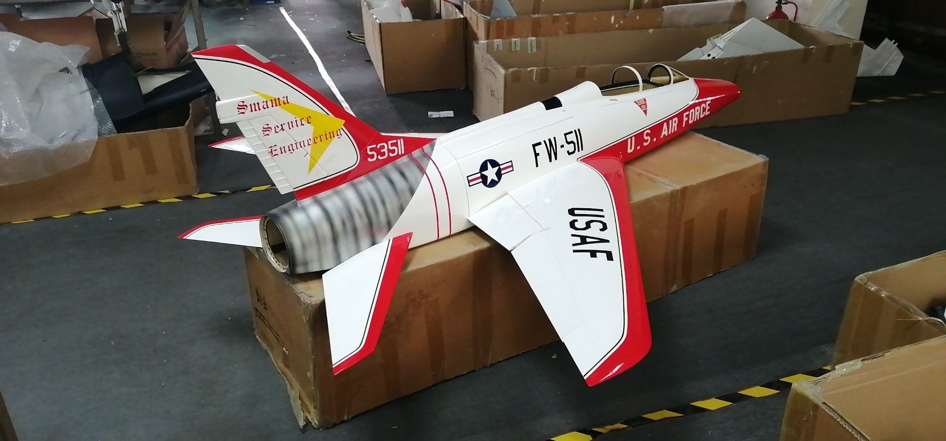
SMAMA on the tail is the initials for Sacramento Air Material Area. There were several "Air Material Areas" in the U.S. In the early 70's the USAF changed the name of these outfits to "Air Logistics Center". I worked at OCALC at Tinker AFB shortly after the name change.
SMAMA on the tail is the initials for Sacramento Air Material Area. There were several "Air Material Areas" in the U.S. In the early 70's the USAF changed the name of these outfits to "Air Logistics Center". I worked at OCALC at Tinker AFB shortly after the name change.

 05-23-2020, 08:18 PM
#10
My Feedback: (167)
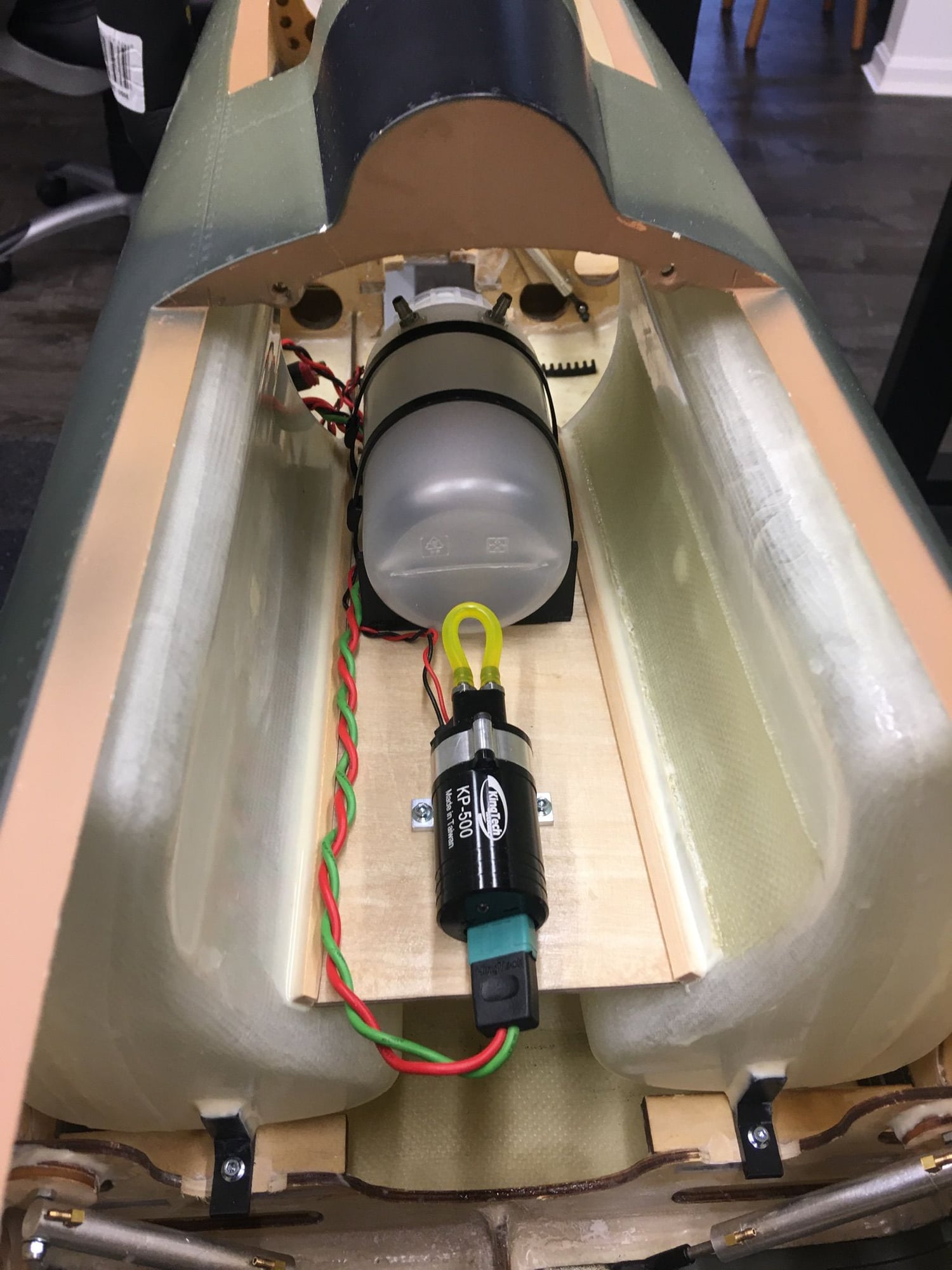
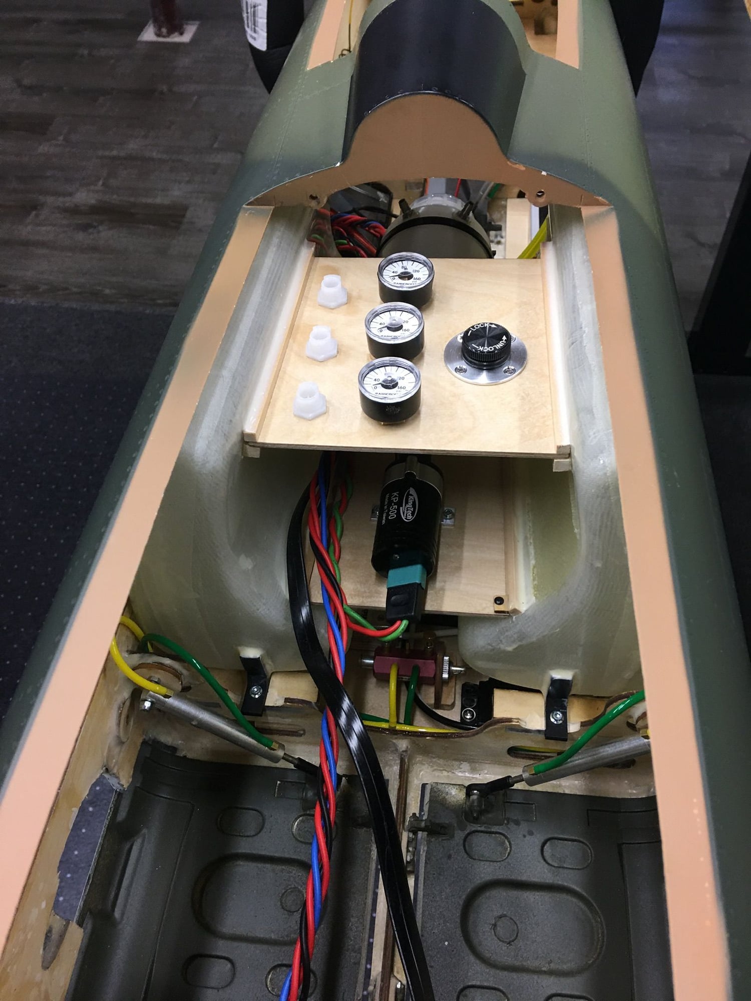
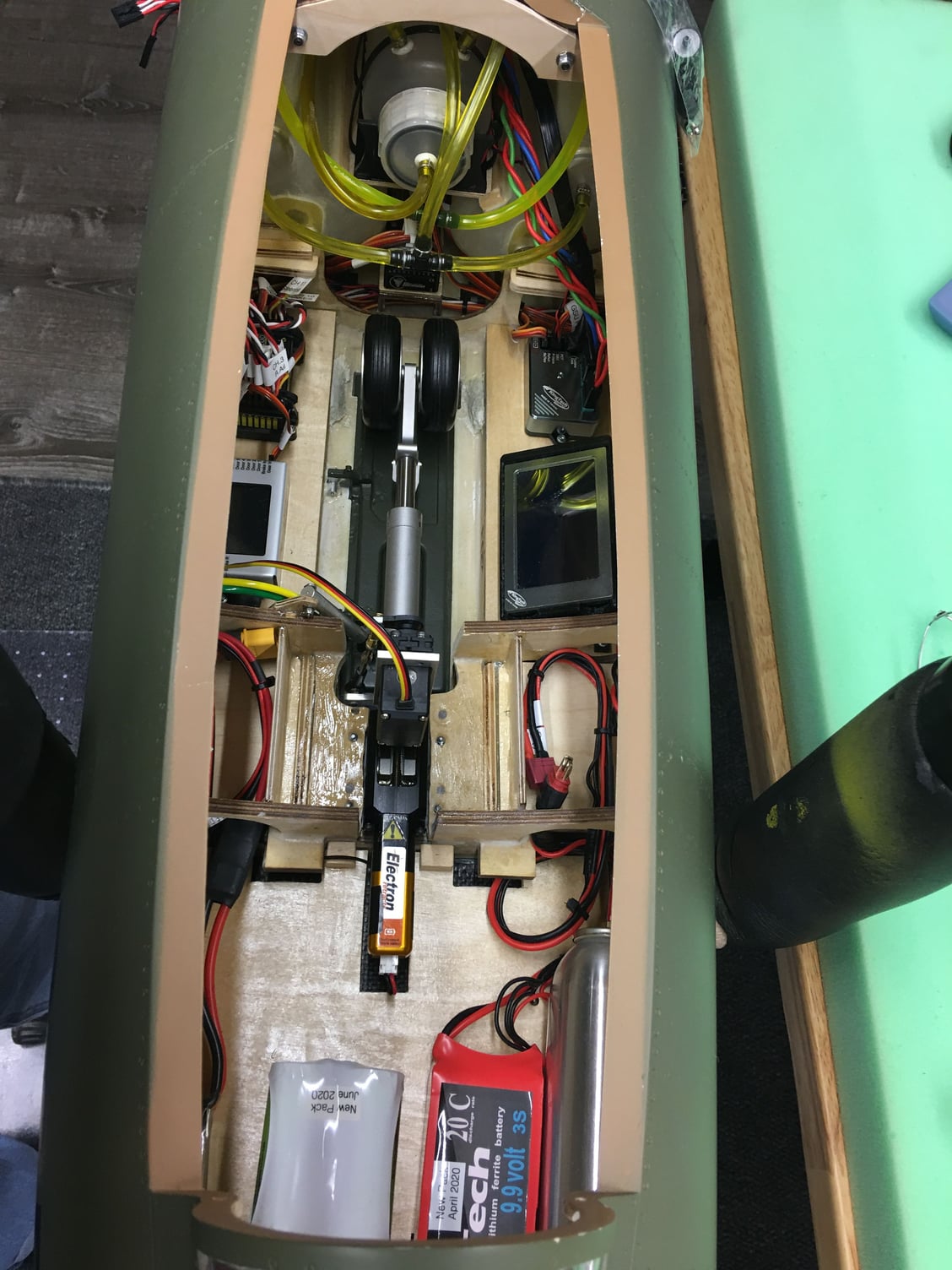
Some pictures of my install. Might help someone utilize the space in the F100. I used the main tanks as tray supports. The trays simply slide in place. This keeps all fuel lines very close and compact to the fuel tanks. All air components are on the bottom of the fuse under the bottom tray. RemovIng one small screw and sliding both trays back gives full access to all air components in seconds. The air components are otherwise tucked neatly out of sight for a clean install.
Fuel tanks are converted to use oring fittings. The main tanks need to be check closely. Mine were so thin that when pressure tested the sides buckled on one of them. Required some additional glass cloth for strength.
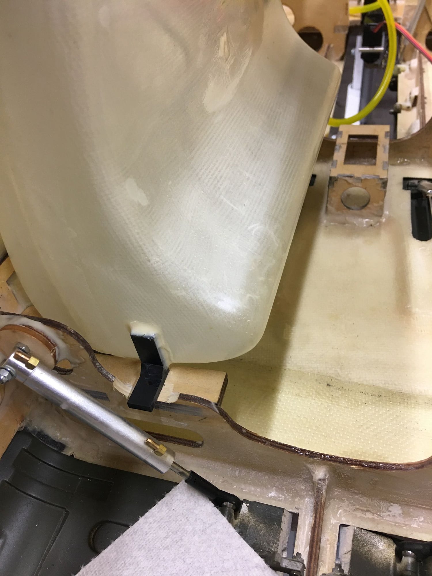
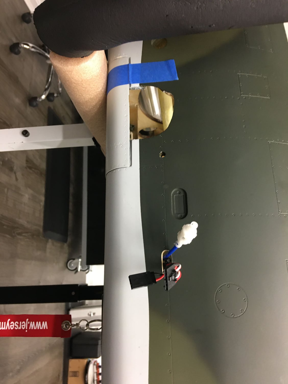
Also added electron gear that uses direct steering mount. The mains are a bolt in replacement but the nose required quite a bit of work. Worth it to eliminate the steering cables. I
The fuselage install is basically done if anyone needs pictures. I can show turbine and pipe install, location for wires to exit fuse for wings, etc.
I spent quite a bit of time modifying this plane including extra carbon fiber reinforcing. The shell is pretty thin in some areas and really needs some extra strength.
Also check the door hinges closely. The nose door on mine had been broken at the factory, then an attempted repair that broke after opening the doors a few times. Installed a set of metal hinges to fix the nose doors.
I will also not run the long inlet. It is cut off right at the front gear mount former. I contacted Skymaster and was told it is not necessary to use the full length inlet. My BVM F100 had a full length inlet and it really limited available space for components. For peace of mind I have seen pics of the new BVM pnp F100 and it does not have full ducting either.
These kits are inexpensive but with some mods they can be made to be very robust F100�s.

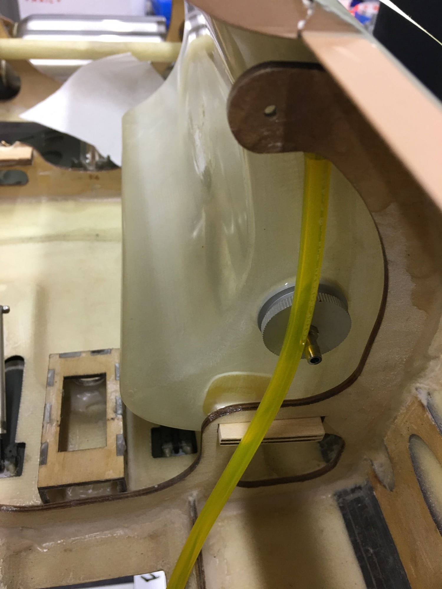

Fuel tanks are converted to use oring fittings. The main tanks need to be check closely. Mine were so thin that when pressure tested the sides buckled on one of them. Required some additional glass cloth for strength.
Also added electron gear that uses direct steering mount. The mains are a bolt in replacement but the nose required quite a bit of work. Worth it to eliminate the steering cables. I
The fuselage install is basically done if anyone needs pictures. I can show turbine and pipe install, location for wires to exit fuse for wings, etc.
I spent quite a bit of time modifying this plane including extra carbon fiber reinforcing. The shell is pretty thin in some areas and really needs some extra strength.
Also check the door hinges closely. The nose door on mine had been broken at the factory, then an attempted repair that broke after opening the doors a few times. Installed a set of metal hinges to fix the nose doors.
I will also not run the long inlet. It is cut off right at the front gear mount former. I contacted Skymaster and was told it is not necessary to use the full length inlet. My BVM F100 had a full length inlet and it really limited available space for components. For peace of mind I have seen pics of the new BVM pnp F100 and it does not have full ducting either.
These kits are inexpensive but with some mods they can be made to be very robust F100�s.
Last edited by Gary Jefferson; 05-23-2020 at 08:48 PM.
05-30-2020, 05:20 PM
#15
My Feedback: (167)
Does anyone have pictures of their cockpit installed? I don�t see any way the cockpit they sent me is going to fit in this F100.
It is way way too big to get inside the fuselage. If someone has installed one and can provide pictures it would be appreciated.
At this point I am looking at cutting it up and making a much smaller tub to make it work.
Thanks, Gary
It is way way too big to get inside the fuselage. If someone has installed one and can provide pictures it would be appreciated.
At this point I am looking at cutting it up and making a much smaller tub to make it work.
Thanks, Gary
Last edited by Gary Jefferson; 05-30-2020 at 05:22 PM.

 06-02-2020, 11:31 AM
#21
My Feedback: (167)
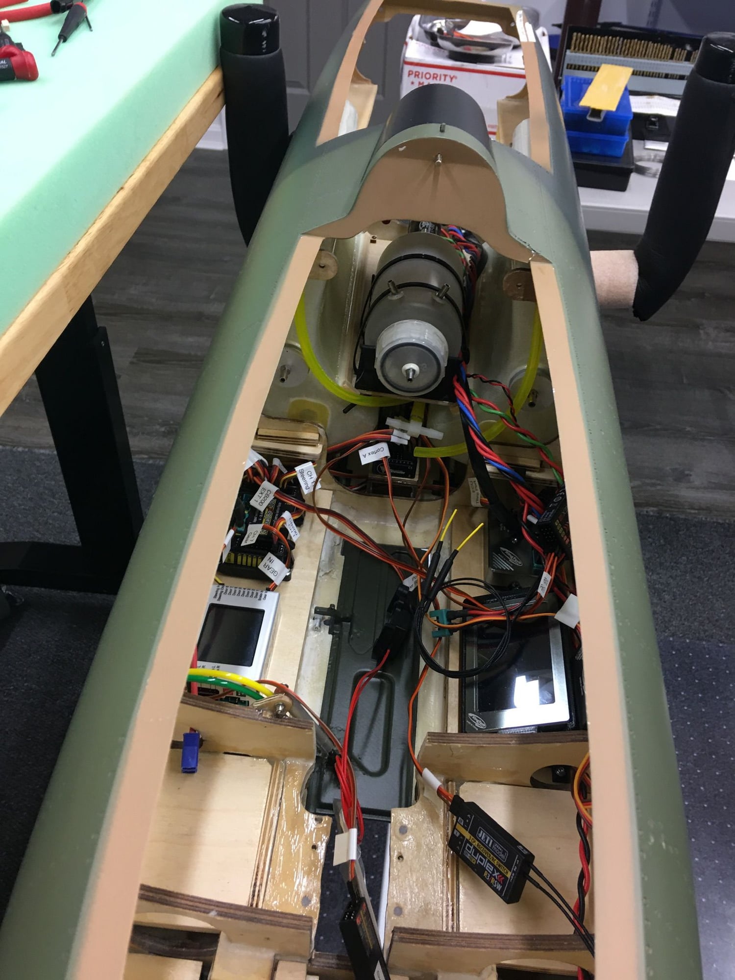
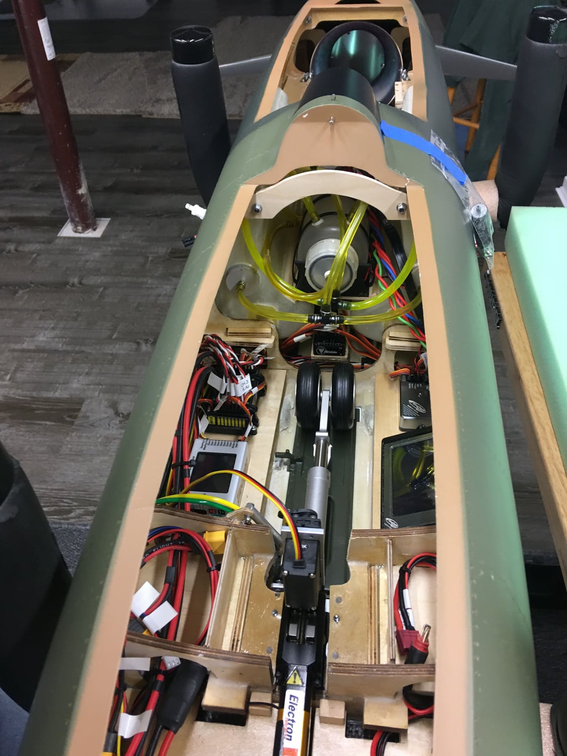
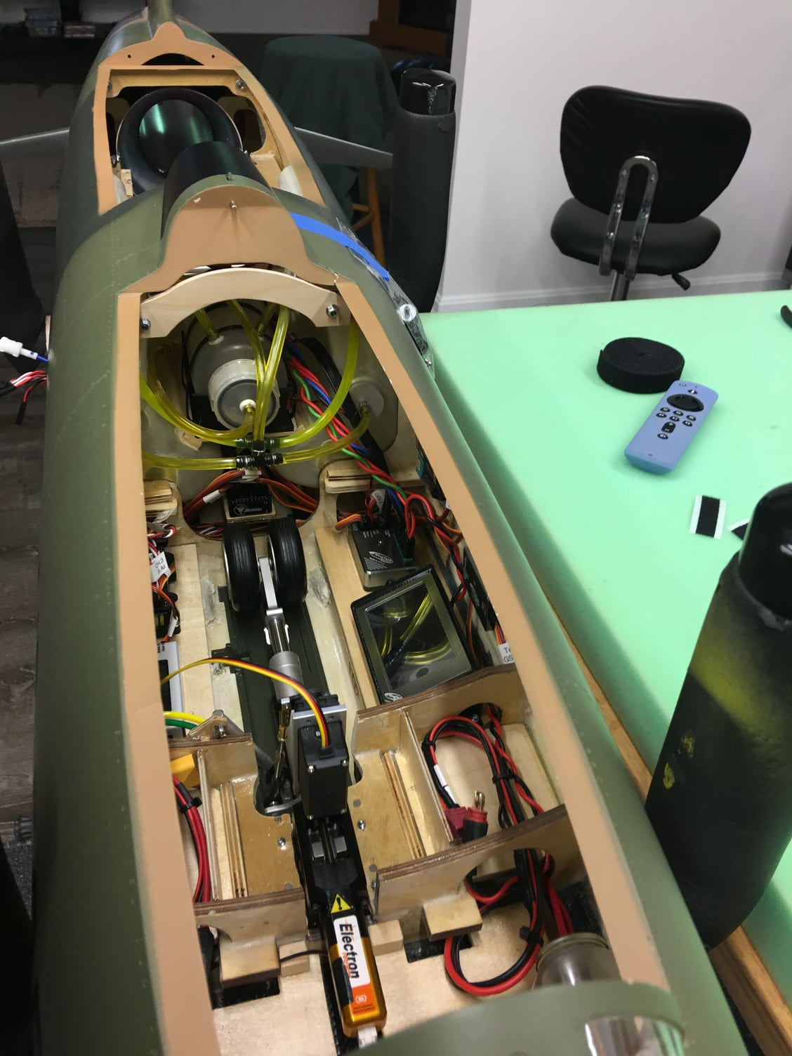
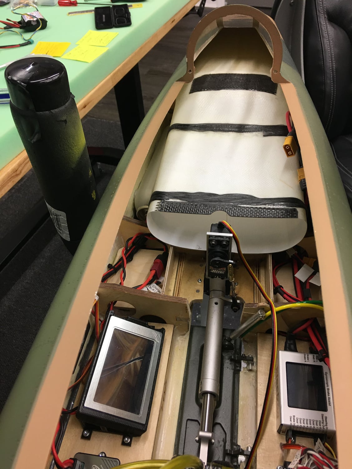
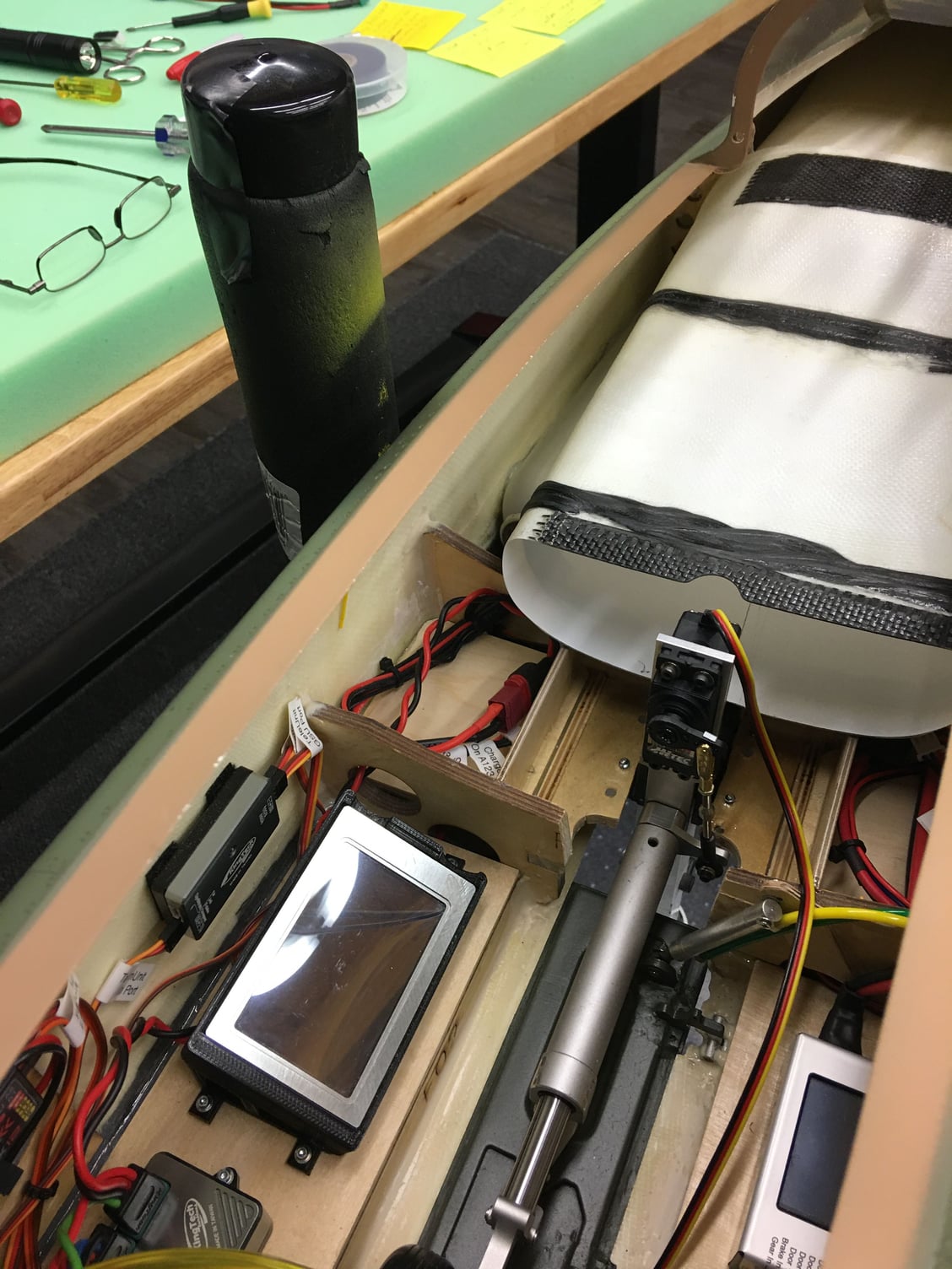
Pictures show where the airlines exit the fuse which is just under the fuel tanks. This picture will save you a lot of time measuring like I had to do to find a good location.
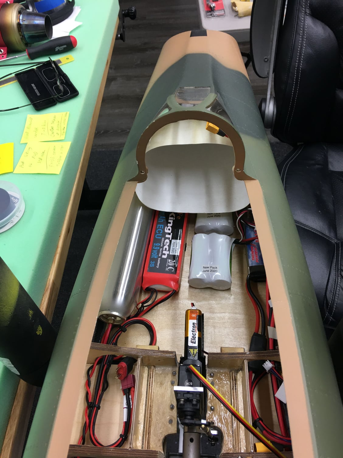
For now all batteries are installed in the nose at least until I check the CG.
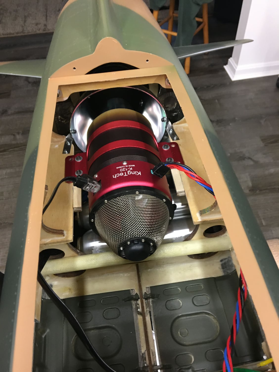
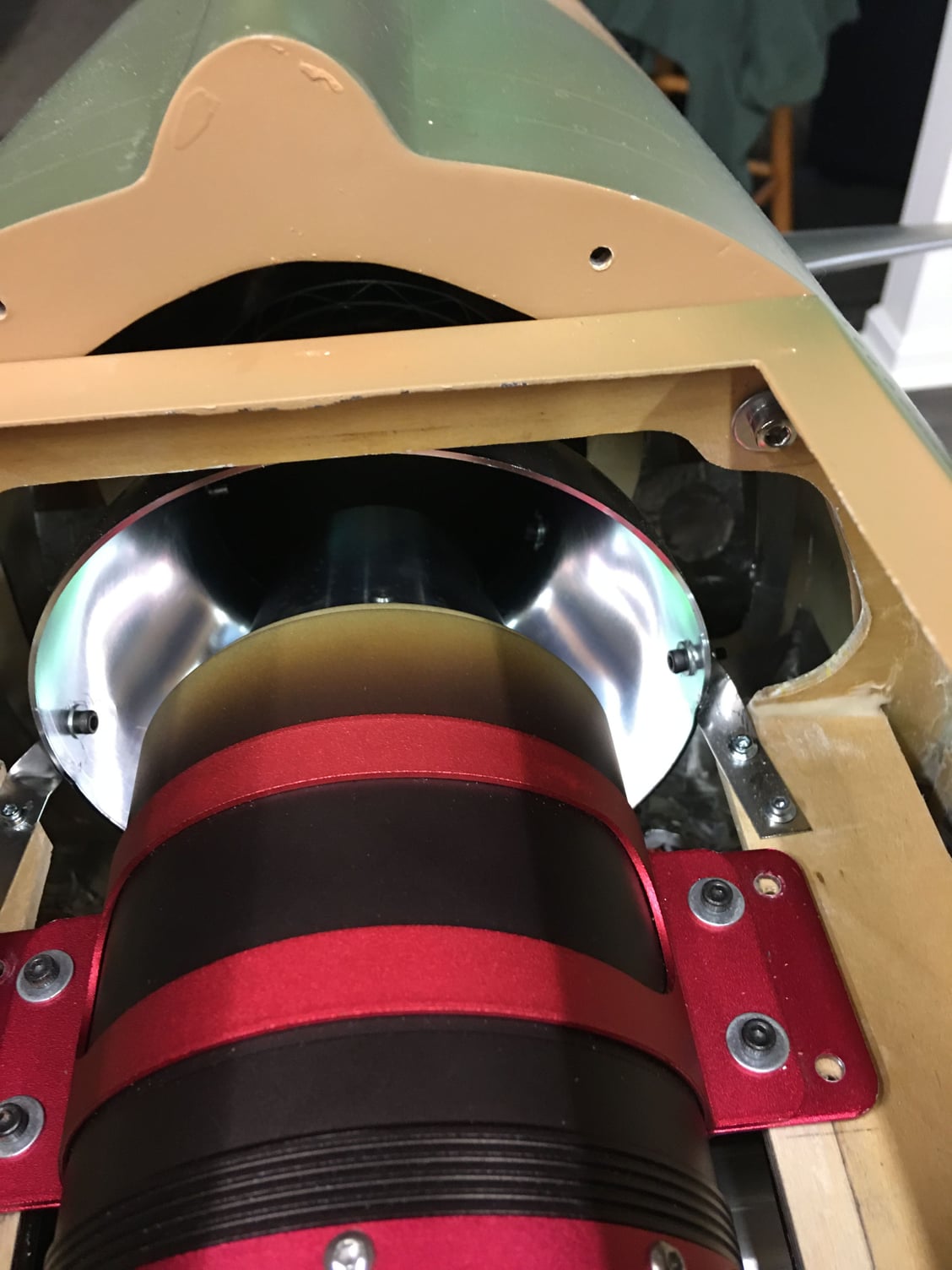
Turbine requires an extension on the engine rails due to the smaller diameter of the K120.
You also need to drill two holes for 4-40 screws in the bell mouth and attach the tail pipe mounting straps to the sides of the bell mouth for rigidity of the pipe.
The short section of inlet is added at the front and cut off at the front gear mount former. It is secured at the bottom by two ply mounting tabs attached to the gear former. This is as far as the inlet will go through the fuselage.
Two air tanks are mounted under the turbine and will be covered with heat blanket.
If you decide to use Electron gear the back former for the gear rail must be cut away for clearance so the steering servo can come up into the fuselage. This is then reinforced on each side by 1/4� ply plates. This is identical to my T1 sport jet design and is a very strong design.
For now all batteries are installed in the nose at least until I check the CG.
Turbine requires an extension on the engine rails due to the smaller diameter of the K120.
You also need to drill two holes for 4-40 screws in the bell mouth and attach the tail pipe mounting straps to the sides of the bell mouth for rigidity of the pipe.
The short section of inlet is added at the front and cut off at the front gear mount former. It is secured at the bottom by two ply mounting tabs attached to the gear former. This is as far as the inlet will go through the fuselage.
Two air tanks are mounted under the turbine and will be covered with heat blanket.
If you decide to use Electron gear the back former for the gear rail must be cut away for clearance so the steering servo can come up into the fuselage. This is then reinforced on each side by 1/4� ply plates. This is identical to my T1 sport jet design and is a very strong design.
Last edited by Gary Jefferson; 06-02-2020 at 11:37 AM.
