


Airworld F5E rennovation
 10-13-2022, 08:04 AM
#51

Thread Starter
Hey,
now thats some very good work on the gear. I have a wire model up and running, and the simulations look real nice, but as soon as i get the load simulation on i am very frustrated. The loads in the up position are becoming enormously high, as the angle is approaching 90 degrees there is no leverage left and the forces just explode. In reality this means that the gear will remain sagged down.....still trying to find a way to cope with that.
Im still amazed how it works on the real thing.
Cheers
 10-13-2022, 12:37 PM
#52
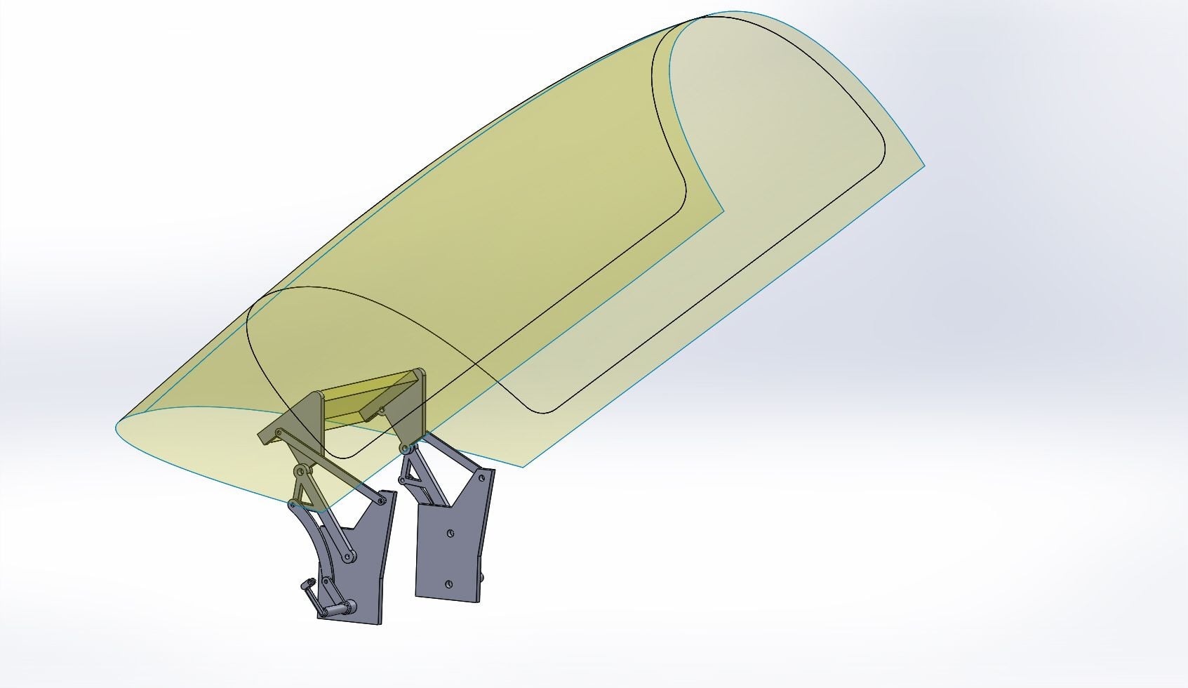
Many thanks for the comment, still working on it as doing another version of the strut and also working on the canopy mechanism. Have not gone into actual loads yet.
I found the gear is deceiving as there are angles that you would not think are there. The gear has a forward slant and also folds out to over 90 degrees when down.
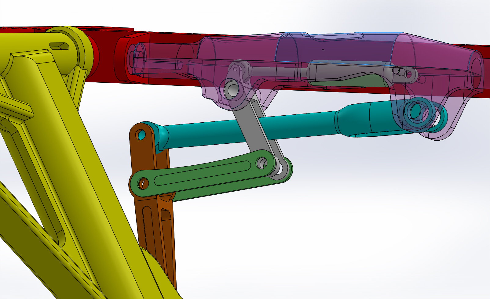
The trunnion (pink) is at an angle to the main strut (yellow) and also the bolt holding the lower brace (brown, blue) to the main gear is angled forward, you are probably aware of this.
I would assume the leverage comes from the angle and distance between the trunnion and the strut, and also the width of the upper/lower side braces and bell crank and side link. There is also a very small distance between the piston attachment point on the bellcrank (grey) and the main pivot with the trunnion for maximum leverage.
Would be interesting to see what you're working with to get a better idea.
Regards,
.
I found the gear is deceiving as there are angles that you would not think are there. The gear has a forward slant and also folds out to over 90 degrees when down.
The trunnion (pink) is at an angle to the main strut (yellow) and also the bolt holding the lower brace (brown, blue) to the main gear is angled forward, you are probably aware of this.
I would assume the leverage comes from the angle and distance between the trunnion and the strut, and also the width of the upper/lower side braces and bell crank and side link. There is also a very small distance between the piston attachment point on the bellcrank (grey) and the main pivot with the trunnion for maximum leverage.
Would be interesting to see what you're working with to get a better idea.
Regards,
.
Last edited by Halcyon66; 10-13-2022 at 12:46 PM.
10-14-2022, 07:10 AM
#53
Thread Starter
Here is what i have. Just wireframe until i have all the load situations accounted for, then ill make parts around the wires...
The long black line in the forward wheel well is actually the rotating axis of the levers. As you can see ive moved it higher up, so that there is always some vertival lever on the gear to hold it up. It has significatly improved load situation, but now i am getting awfully close to the top skin.....
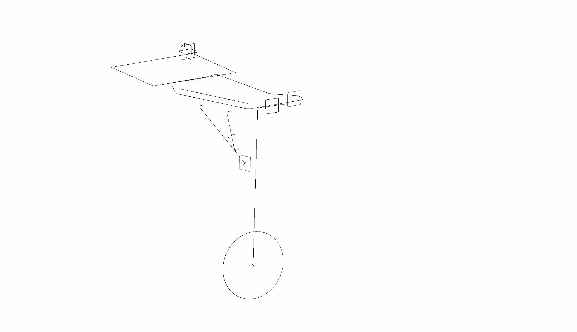
The long black line in the forward wheel well is actually the rotating axis of the levers. As you can see ive moved it higher up, so that there is always some vertival lever on the gear to hold it up. It has significatly improved load situation, but now i am getting awfully close to the top skin.....
10-14-2022, 02:15 PM
#54
Properly designed landing gear would have the same force required through the retract sequence, and I am sure this gear is just that. The designers knew what they were doing.
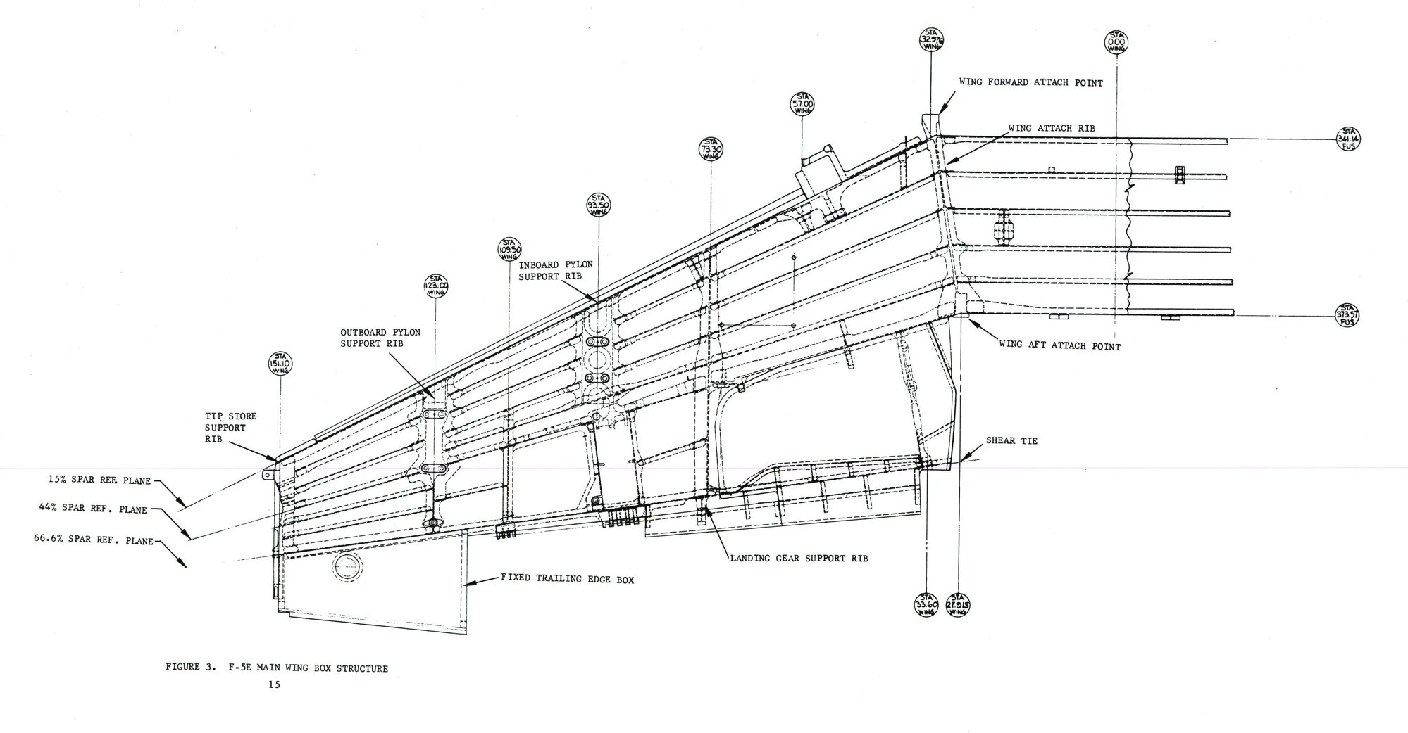
Both the strut and trunnion are in the same plane, the structural image shows this.
There is really only one main force operating the gear and that is the piston. That in turn operates the bell crank which then �pulls� up the strut.
The upper and lower side braces are just that and they increase the leverage of the bell crank and side link. They all work together as they have fixed pivot points.
If you try to simulate this retrack by rotating the trunnion the force would be massive, yet as said the piston pulls the strut up and the secondary result is that the trunnion rotates as the distance between the bell crank and lower brace bolt diminishes.
Regards,
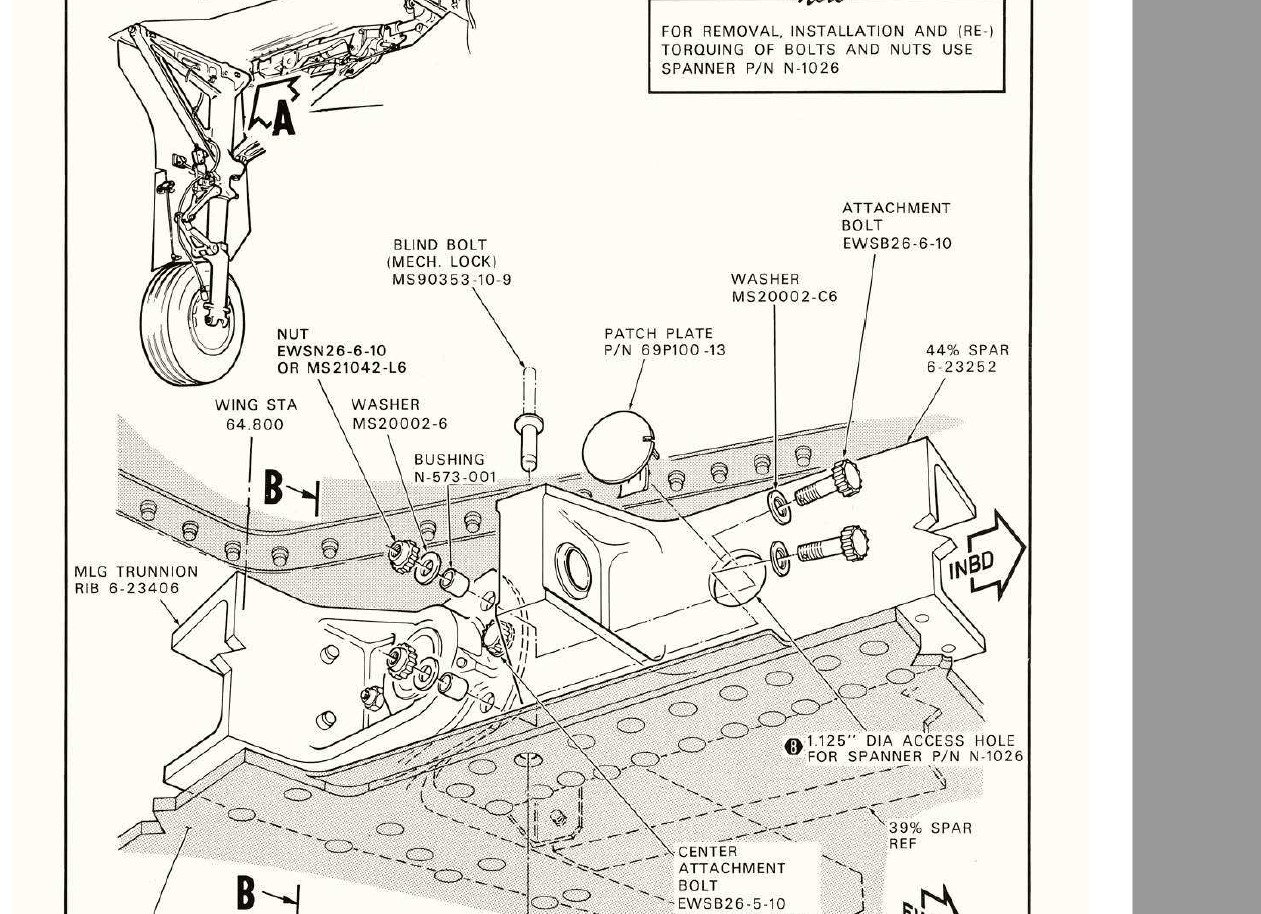
10-18-2022, 01:54 PM
#55
Thread Starter
I'm sure the northrop guys did their work well. But they cannot superceed physics. There needs to be an alternate source for torque momentum.
If you rotate the gear into the up position, it needs to be held there with a certain torque momentum. Its defined by gear weight, g load and leverage available.
If the trunion plane is the same as the strut plane, then approaching the up plane the leverage will strive towards 0 ant therefore the the force will strive towards indefinite.
there needs to be an alternate source to generate the required momentum, and it cannot be generated if located within the same plane.... (momentum = force x leverage)
10-20-2022, 06:40 PM
#56
Your diagram does not make sense to me as I have never used wireframe models like that.
You do not have the pivot points working off each other as the real gear does and therefore it would be difficult to simulate the retraction.
As said before it seems very difficult yet once CAD'd it up it made perfect sense to me, and the action seems very logical.
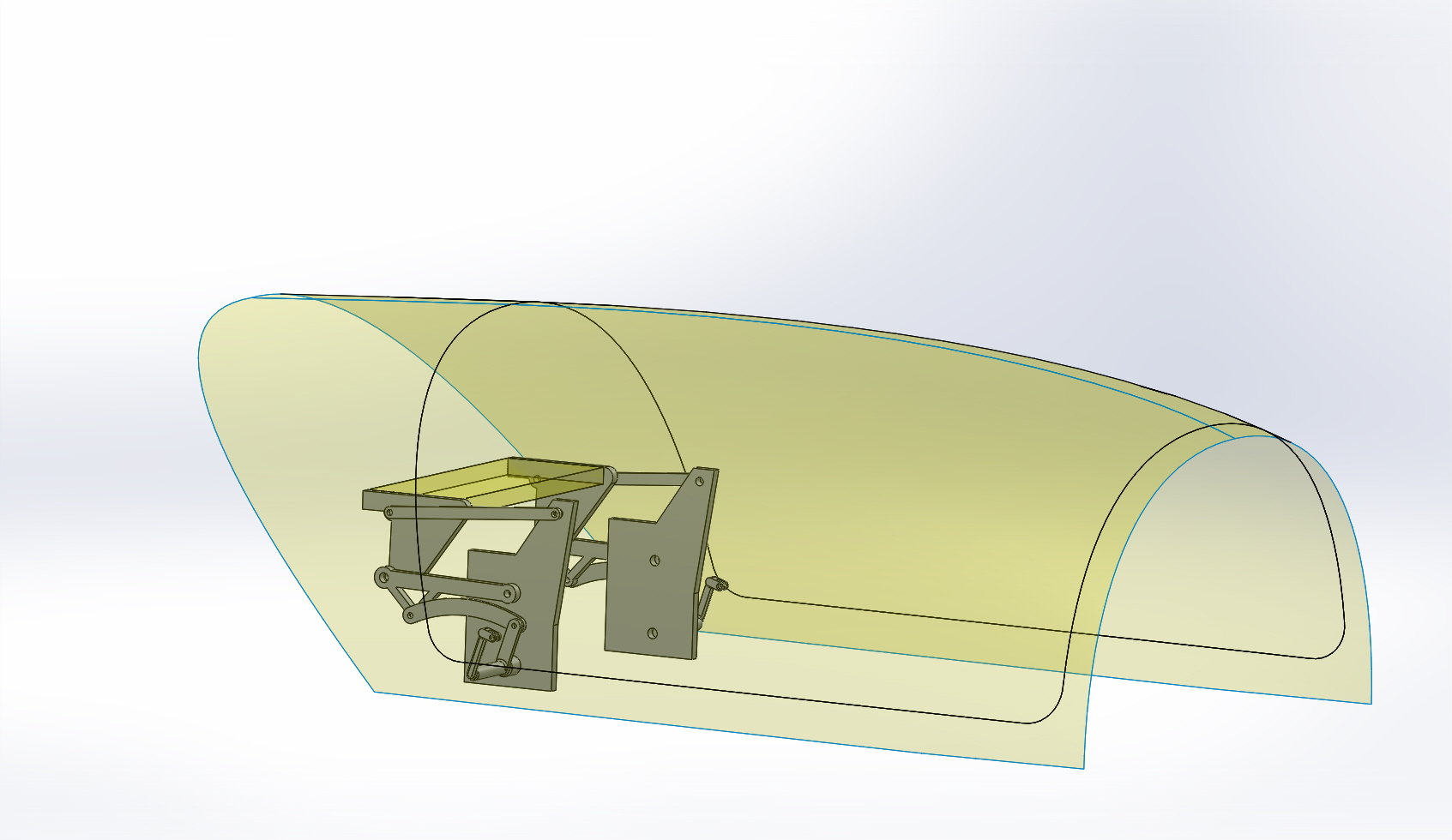
I have almost redone the main strut to the heavier version and almost figured out the canopy mechanism with a rough CAD.
Then on to the fuse.
Regards,
You do not have the pivot points working off each other as the real gear does and therefore it would be difficult to simulate the retraction.
As said before it seems very difficult yet once CAD'd it up it made perfect sense to me, and the action seems very logical.
I have almost redone the main strut to the heavier version and almost figured out the canopy mechanism with a rough CAD.
Then on to the fuse.
Regards,
Last edited by Halcyon66; 10-20-2022 at 07:02 PM.
10-21-2022, 04:12 AM
#57
Thread Starter
Wireframe models make very much sense in developing kinematics. Automotive industries uses it in their designs as a basis (i used to do this professionally for BMW). You have one base file defining all joint positions as points and joint axles. Then these are exported with links into individual part files, so they will serve as basis to design the part around it.
Following advantages:
-You can test the wireframe easily without much effort until motion is satisfactory and loads are satisfactory without ever designing a single part
-Adapting a point in the base file automatically corrects position in ALL linked files, so you do not have to redesign anything when changing the kinematics. If the parts are drawn referenced to the imported points, it will even automatically correct all parts.
10-24-2022, 05:34 PM
#58
Been using SolidWorks for over 20 yrs, never found anything else as capable. Expensive yet you get what you pay for.
More and more add-ons available and the scan to 3D is great.
Regards,
More and more add-ons available and the scan to 3D is great.
Regards,
10-25-2022, 02:25 PM
#59
Thread Starter
Depends
SW CFD is very good, the FEM is average to marginal. But then again everything lies in the eye of the user, and accuracy is 95% dependant of user input....so in the end it will be life rule of digitalization #5: shhit in shhit out.
Have you done a force analysis on the gear kinematics?
Cheers
SW CFD is very good, the FEM is average to marginal. But then again everything lies in the eye of the user, and accuracy is 95% dependant of user input....so in the end it will be life rule of digitalization #5: shhit in shhit out.
Have you done a force analysis on the gear kinematics?
Cheers
Last edited by Miniflyer; 10-25-2022 at 02:30 PM.
10-25-2022, 07:33 PM
#60
I did sims thru SW with material properties (part weights and the like) and my results were that the forces required were not extreme. I am not sure you're taking into account the two-lever action of the gear, the grey bell crank pulls the green side brace which then levers against the blue main brace. Also the trunnion and gear are not 90 degrees.
Also the force required was pretty constant through the full retract sequence. Not sure if I will use a piston or a screw jack. I think PSI for a piston would be rather high, yet speed with a screw jack would be somewhat slow. Perfect would be an ultra-motion unit yet too large.
As before finishing up the new strut and then some fine tuning and then get parts off to my CNC guy.
Regards,
