1/7th F-14D Scratch build thread *building started*
 06-15-2013, 03:42 PM
#1101

Getting closer by the minute.
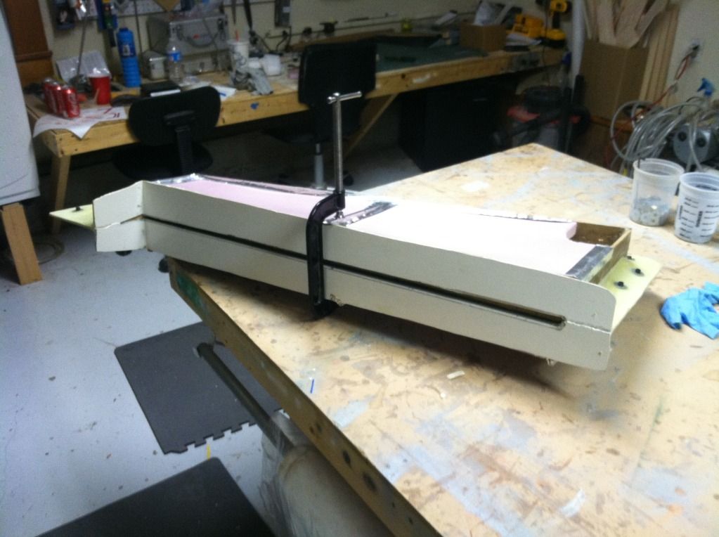
My CF arrived so i was able to finish up the internal structure for the vertical stabs and close those molds:

Then my buddy Tom and I started work on the left wing bottom skin. The glass, CF and core material was put in place, then all of the carbon wing spar cap material was placed in the slot in the core material.


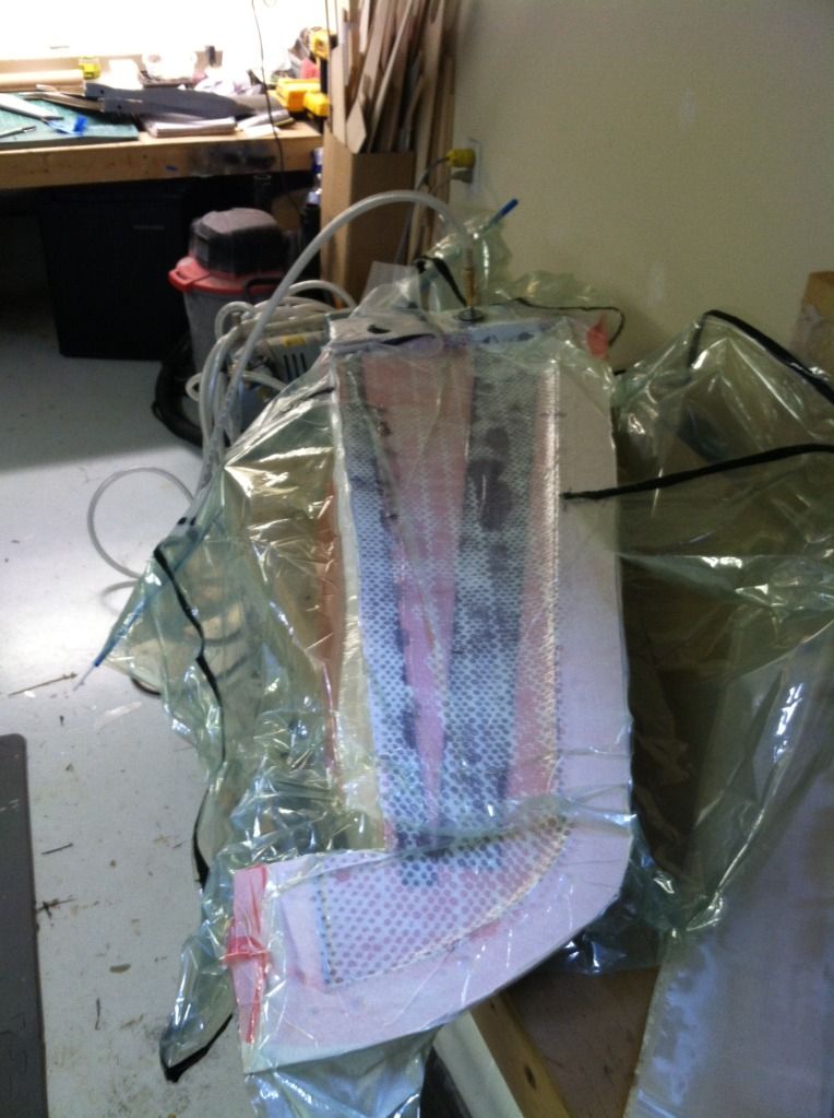
Then the last layer of carbon fiber and glass was put in and and then the entire thing was placed in the vacuum bag. Tomorrow ill pull this out, pop the vertical stab parts out of the molds and layup the left top wing skin:

My CF arrived so i was able to finish up the internal structure for the vertical stabs and close those molds:
Then my buddy Tom and I started work on the left wing bottom skin. The glass, CF and core material was put in place, then all of the carbon wing spar cap material was placed in the slot in the core material.
Then the last layer of carbon fiber and glass was put in and and then the entire thing was placed in the vacuum bag. Tomorrow ill pull this out, pop the vertical stab parts out of the molds and layup the left top wing skin:
 06-16-2013, 06:47 AM
#1102
Both vertical fins came out perfect! Their weights average 9oz each.
 .
.
The bottom wing skin also came out perfect! This skin is currently 17.7oz, if you double that and add in the weight of the materials for the internal structure, eac wing panel should come out around 3lbs. I am happy with that number, as the strength of just this wing skin is very impressive!

And a closeup of some of the some of the detail:

. The bottom wing skin also came out perfect! This skin is currently 17.7oz, if you double that and add in the weight of the materials for the internal structure, eac wing panel should come out around 3lbs. I am happy with that number, as the strength of just this wing skin is very impressive!
And a closeup of some of the some of the detail:
06-16-2013, 08:29 AM
#1103

Hi Thomas:
Those wings look great, can you sow us the internal structure ? please. Thanks in advance.
Congrats for your pretty Tomcat, my favourite model, I love it.
Regards from Spain
Carlos Márquez
____________________________________
www.cmjets.blogspot.com
Those wings look great, can you sow us the internal structure ? please. Thanks in advance.
Congrats for your pretty Tomcat, my favourite model, I love it.
Regards from Spain
Carlos Márquez
____________________________________
www.cmjets.blogspot.com

 06-16-2013, 10:09 AM
#1106

DUUUUUDDDEEEEE,!!!!!!!
AWESOME
Can't wait to start building up my hobby fund Soon
ORIGINAL: invertmast
Both vertical fins came out perfect! Their weights average 9oz each.
.
The bottom wing skin also came out perfect! This skin is currently 17.7oz, if you double that and add in the weight of the materials for the internal structure, eac wing panel should come out around 3lbs. I am happy with that number, as the strength of just this wing skin is very impressive!
And a closeup of some of the some of the detail:
Both vertical fins came out perfect! Their weights average 9oz each.
. The bottom wing skin also came out perfect! This skin is currently 17.7oz, if you double that and add in the weight of the materials for the internal structure, eac wing panel should come out around 3lbs. I am happy with that number, as the strength of just this wing skin is very impressive!
And a closeup of some of the some of the detail:
06-16-2013, 04:27 PM
#1107
The top wing skin is in the vacuum bag:
Then i machined up the components needed toinstall the bearing holders. The one on the bottom left is for cutting the wing skins to the correct size for the bearing holders to rest into. The center hole is for bolting the piece in place, then a permagrit bit is put in the other hole and the dremel spun in a circle. The recessed portion is recessed the exact amount needed to cut through the skin and core, but not into the mold.
Its allot easier to show how it works and is setup than explain it, so ill show it in a video later.
The other two parts are used to locate the bearing holder in the exact position of the pivot CL.

I also routed out the base of the vertical fins so the rudders could be test fit. Believe it or not, this is the first time the rudders have ever been installed correctly into the vertical fins. The fit is very good.

Then i machined up the components needed toinstall the bearing holders. The one on the bottom left is for cutting the wing skins to the correct size for the bearing holders to rest into. The center hole is for bolting the piece in place, then a permagrit bit is put in the other hole and the dremel spun in a circle. The recessed portion is recessed the exact amount needed to cut through the skin and core, but not into the mold.
Its allot easier to show how it works and is setup than explain it, so ill show it in a video later.
The other two parts are used to locate the bearing holder in the exact position of the pivot CL.
I also routed out the base of the vertical fins so the rudders could be test fit. Believe it or not, this is the first time the rudders have ever been installed correctly into the vertical fins. The fit is very good.


 06-17-2013, 08:42 PM
#1112
So here we go!
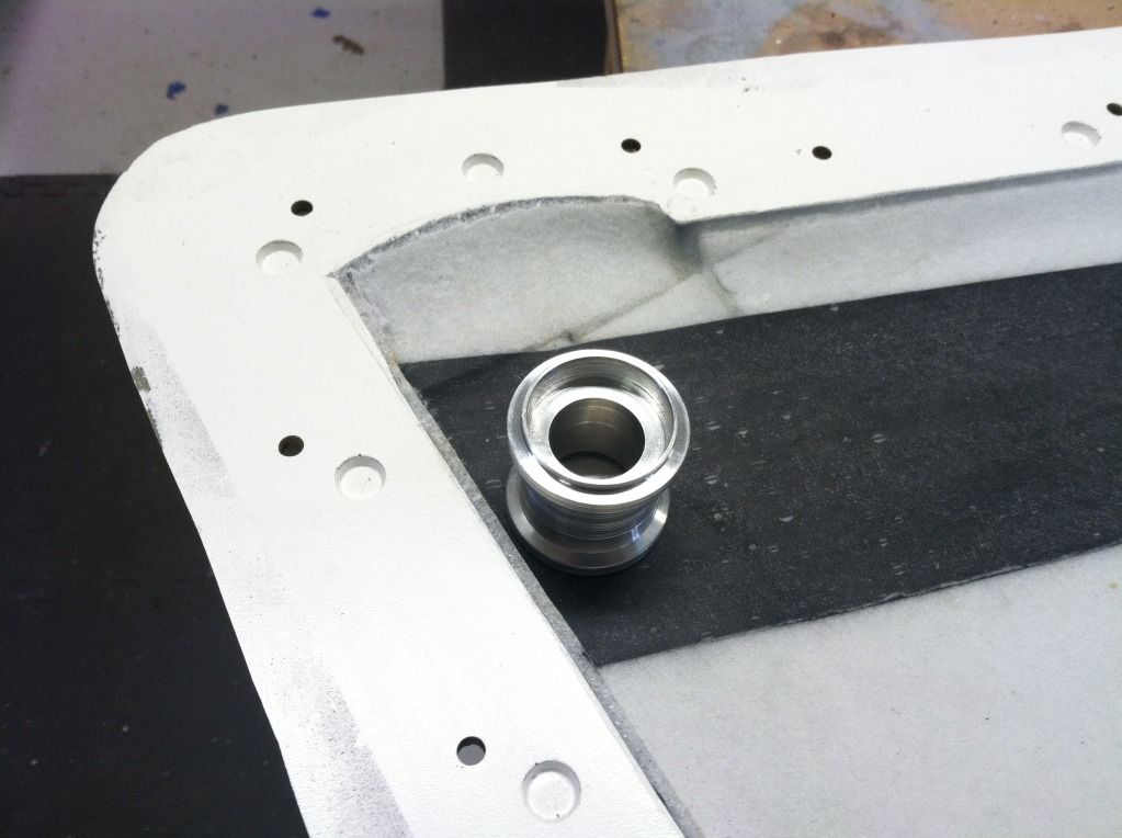
Here my cutting jig tool has been completed. The cut off bolt goes into the pivot point location (this location was designed into the molds so every wing will have it in a indentical position). The permagrit tool was then used to cut out the wing skin so the bearing holder can be put in place:

Then the bearing holder located donuts were bolted through the same point in the mold:

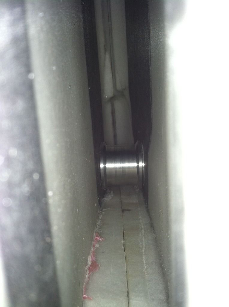
Then the bearing holder was test fit:
This was repeated for the top wing skin as well. I had to modifiy the dimensions on the bearing holder (good thing for having my own lathe now) so i will have to update the CAD files to reflect the correct size.
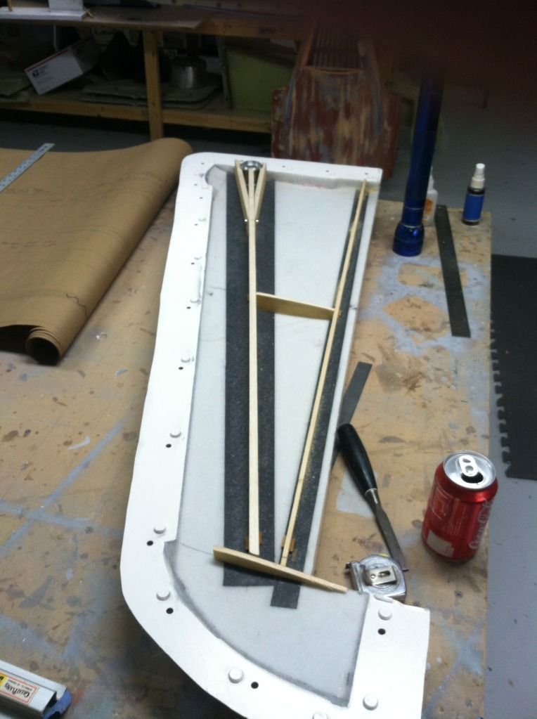
Then i began work in the internal structure for the wing.
First up the main spar shear webbing. You can also see how it is a 3 piece affair at the bearing holder location so it is sandwiched in position to keep it from moving.

Then the sub spar/flap hinge spar and two wing ribs were made up. I still have a few parts to make for wing root, which i plan to do tomorrow.
Here my cutting jig tool has been completed. The cut off bolt goes into the pivot point location (this location was designed into the molds so every wing will have it in a indentical position). The permagrit tool was then used to cut out the wing skin so the bearing holder can be put in place:
Then the bearing holder located donuts were bolted through the same point in the mold:
Then the bearing holder was test fit:
This was repeated for the top wing skin as well. I had to modifiy the dimensions on the bearing holder (good thing for having my own lathe now) so i will have to update the CAD files to reflect the correct size.
Then i began work in the internal structure for the wing.
First up the main spar shear webbing. You can also see how it is a 3 piece affair at the bearing holder location so it is sandwiched in position to keep it from moving.
Then the sub spar/flap hinge spar and two wing ribs were made up. I still have a few parts to make for wing root, which i plan to do tomorrow.
 06-17-2013, 10:50 PM
#1115

Hi Thomas, great work man I will follow this. My stuff is now also in the house so I will start molding too, first the little parts and later the big one .
Regards, Peter
.Regards, Peter
06-18-2013, 02:35 PM
#1116
Peter,
Good to hear, now get back to work! Lol
A bit more progress:
I finished up all of the parts for the internal wing structure. Due to my design of the carry teough spar in the fuselage, i will have to notch the wing root, i hoped i wouldnt have to, but oh well.
Then i realised i needed a hard point for the pivot actuator mount to attach. So some 1/4" aircraft ply was cut to fit between the wing root and the bearing holder. The main spar sheer webs were modified to allow for this ply plate to fit.
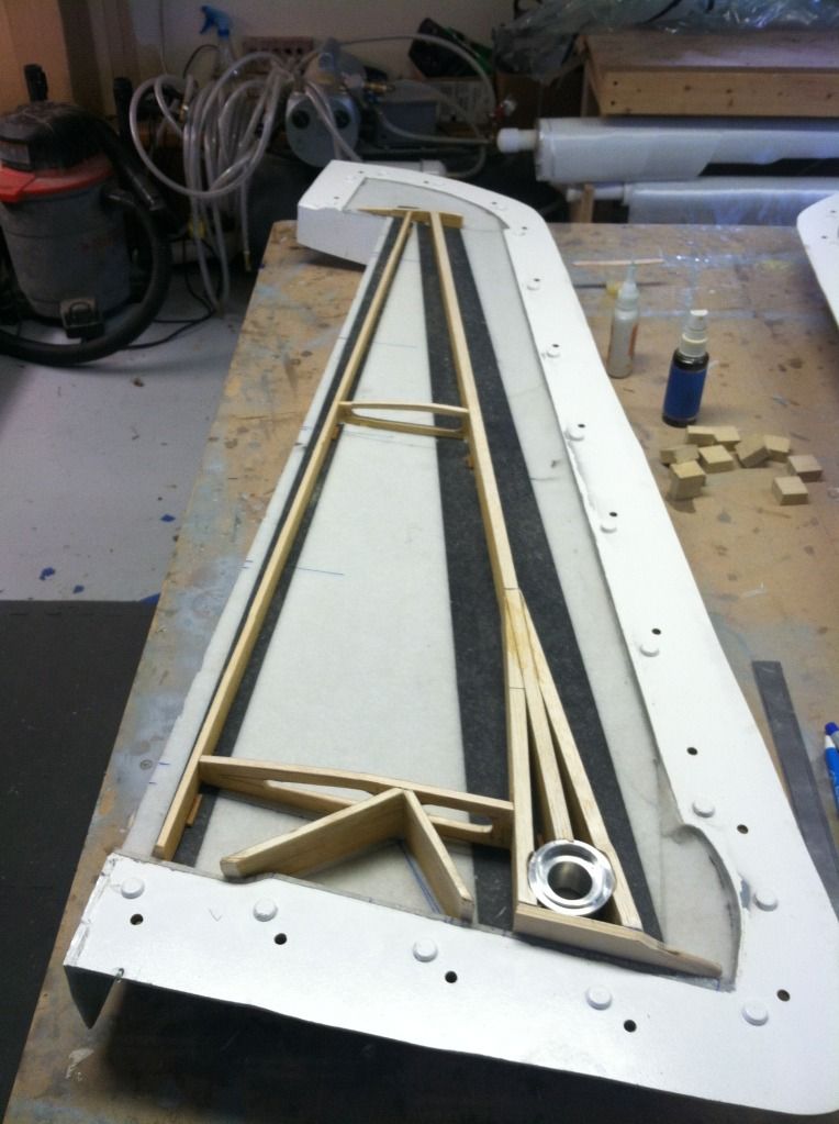
I then epoxied all of the main structural parts together (main sheer webs, sub spar, wing ribs). Then i rough cut a bunch of 1"x2" hard balsa blocks for the flap hinge mounts. Ill sand them to the proper shape and epoxy them to the sub spar later this evening.

All that is left to do to the internal structure after the hinge blocks is to drill the ply plate for the pivo actuator mount bolts and install the blind nuts. Once that is done, the wing molds can be closed together permanently. I hope to do that tomorrow!
Good to hear, now get back to work! Lol
A bit more progress:
I finished up all of the parts for the internal wing structure. Due to my design of the carry teough spar in the fuselage, i will have to notch the wing root, i hoped i wouldnt have to, but oh well.
Then i realised i needed a hard point for the pivot actuator mount to attach. So some 1/4" aircraft ply was cut to fit between the wing root and the bearing holder. The main spar sheer webs were modified to allow for this ply plate to fit.
I then epoxied all of the main structural parts together (main sheer webs, sub spar, wing ribs). Then i rough cut a bunch of 1"x2" hard balsa blocks for the flap hinge mounts. Ill sand them to the proper shape and epoxy them to the sub spar later this evening.
All that is left to do to the internal structure after the hinge blocks is to drill the ply plate for the pivo actuator mount bolts and install the blind nuts. Once that is done, the wing molds can be closed together permanently. I hope to do that tomorrow!
06-18-2013, 03:37 PM
#1117


Thomas, it looks beautiful, but I still question (and perhaps I'm not fully understanding how your spar works) the strength of it bearing pivot block. IMO you would benefit a huge amount from even just a 1/8" full depth aluminum spar tig welded to the bearing housing that extends a good 10" or so out into the wing. It could sandwich between the main spar with bolts and hysol. As it sits right now, your main spar is great, but there is still little more than your wing skin holding the bearing block. I am not questioning your skill, but after years as a machinist and die maker offering my thoughts on arguably the most critical structure piece of your wing.
06-18-2013, 04:48 PM
#1118
Jeremy,
I understand where your concern is, and i agree whole heartedly. The pivot to wing spar junction is by far one if the most critical aspect of the model.
I do believe allot of peoe are getting confused about what they are thinking is the wing spar, so ill take some time to try and explain it better.
The primary wing spar is NOT the big piece of wood you see going around the aluminum bearing holder. Matter of fact, if you take one molded wing skin (just a top OR bottom), the primary wing spar is already in the wing skin.
There are over 300,000 individual strands of carbon fiber in each of the Integral primary main spar. This spar is sandwiched between the unidirectional carbon fiber and glass cloths. The unidirectional carbon is also part of that primary spar.
The hole for the bearing holder in the skin is surrounded about 60% of its circumference with carbon fiber tow, when the hole is cut to the correct size, the bearing holder is a snug fit and should not move at all, if ever.
The big chunk of wood you see is a secondary spar to the integral carbon spar. Its primary purpose is to act as a shear web to keep the upper and lower wing skin in correct location to each other. Its secondary purpose is to assist in preventing bending moments. I tested this component separately by hanging 30lbs of lead from the end of it (roughly 1/2 of the models flying weight). It deflected roughly 1/16".
The way it Y'a off is theoretically going to lock the aluminum piece into position.
Hopefully all that makes sense. Again, i fully expect this wing to not last through the stress testing, but it it does, that will be even better and is why i am building it as if it were to be a flying part. Because if it does survive, it will be a flying part!
06-18-2013, 11:30 PM
#1119

Join Date: Jul 2006
Location: Norfolk , UNITED KINGDOM
Posts: 1,409
Likes: 0
Received 0 Likes
on
0 Posts
Thomas
Unlike many of the desk based builders, you have with a magnificent effort, made a detailed mould and all the parts for the one of the most complex and difficult to make model aircraft. You have given it lots of thought. I congratulate you for the effort. As you say the way to prove you are right is to stress test the parts.
I dont think that there has been a thread that discusses what a testing regime should comprise. It would be interesting to share your thoughts with us. This might then form a blueprint for others to follow in testing their large models. I presume you will test the complete plane or were you thinking of testing each component separately?
John
06-19-2013, 03:08 AM
#1120
John,
I have had always planned to do some stress testing as its a necessity for a new model of this size. Per the AMA, we arent required to do any of this testing, which i dont fully agree with. As far as the testing regime, it will all be kind of crude and i will only test those components i feel really need it (horizontal stabs, wings, and wing/fuse assembly).
This wing will be tested individually to prove (or disprove) my layup and structure design is adequate. If it is, great. If not, back to the drawing board and i will have to ponder everyones suggestions on what will be best to try next.
As far as directions for the testing, i will probably use the LMA certification guidelines you guys have overseas.
06-19-2013, 07:29 AM
#1121
Join Date: Jul 2006
Location: Norfolk , UNITED KINGDOM
Posts: 1,409
Likes: 0
Received 0 Likes
on
0 Posts
Thomas
There is no UK LMA procedure for weight testing. All we did was use a modified from of what the Germans use.
The first thing I guess is to decide what G you should test to. I expect that you have used an Eagletree G force add on and have your own ideas of what forces is reasonable to design for. I think about positive 7G is a good compromise and then add a small margin of safety. If your plane weighs say 30 Kg wet then the weight testing would need over 210Kg which is a lot of weight. If you listen to those who really throw their planes about then you may go for a larger figure. The next question is do you do a negative G load test as well. If you do clearly there is no need to make it as severe as the positive.
You have then to decide how to distribute the weight and how much the fuselage contributes to lift. The wings will clearly have less weight loaded to the outside than the inside. i.e. you need to know the lift distribution or approximate for it. We divided our wing into notional strips and worked out what load should be put in which strip.
Measuring the positive G you need to invert the plane. You have to decide how to support the plane. I see that the FEJ F-14 test that the Germans carried out was supported with hard mounts under the fuselage wing roots. Mine was supported on a foam block that was fitted to the underside of the centre fuselage section.
http://www.youtube.com/watch?v=7cC9WqQKifw
With the plane in place you measure the distance from the wingtips to the floor, after the weight test you check there has not been any permanent deformation.
You have to decide what weight to use, convenient weight is sand, in say sealed 10 kg bags. We used 1kg bags of flour and donated it to charity after the exercise. I would always video the exercise so that there are no arguments that it has been fudged.
The stabs are more of a controversial issue. I guess they too should be loaded with weight, but how much I have no idea. My plane was a delta so I did not have this to worry about. More importantly though I would test an unknown all flying tail in a rig attached to a car at an airfield at say 80-90mph, just to check the pivot point is in the right point and the servo does not have to draw excessive current to hold it steady. If you look at the video of the Yak 130 that the Russians flew at WJM that is exactly what they did.
http://www.youtube.com/watch?v=IzJablEAGW8
(look at 3:54)
You would also get some warning about flutter at low speed. I have seen a large jet crash because the pivot was not in the correct place and despite having a powerful servo it could not hold it in place for flight. A simple test to do.
Twin fins on some of our jet models can be a problem. I have seen rudders on F-22's flutter and fall off. They too could be tested on a car as with the Yak.
When the plane has passed the LMA procedures in the UK we have to do minimum of 6 flights or 1 hours flying before we can fly in public for this weight of plane.
Having seen what you have done I would be surprised if you did not managed to pass a weight test.
John
06-19-2013, 07:29 AM
#1122
Hi Thomas, thanks for the explanation, sounds much better then I had pictured it. I still think that in the event of a failure, that will be the weak point, however, with the explanation you've given, I think that the failure point would be well beyond any stresses it might see in flight. I can't wait to see your tomcat finished! I'd be on board for one, but I know a large twin engine jet just isn't in my near, or probably distant future. I will however gladly sit back and enjoy through envious eyes!
06-19-2013, 07:47 AM
#1123
John,
Exactly my thoughts. As far as the G loading, i plan as a minimum of 10G's, that should suffice. The fuselage contributes to about 3o-40% of the lift. Lots of things to decide when i get to that point of the project. But at a 65lb flying weight and 10G load factor, that works out to roughly 210lbs of weight per wing panel, assuming a 35% lift support from the fuselage.
If my pseudo cad testing of the wing spar is correct, it should support 300lbs.
Again, we will find out soon enough. I need to make the slat plug using this wing before i stress test it, but that should only take a day or four. But work is also beginning to get busy, so it may be awhile before i get to testing he wing.