


Installing the Turnigy 9X Backlight Kit in your Spektrum DX6i; A BETTER Way.
 04-26-2013, 10:54 PM
#1
Senior Member
Thread Starter

Join Date: Jul 2012
Location: Victoria TX
Posts: 615
Likes: 0
Received 0 Likes
on
0 Posts
Installing the Turnigy 9X Backlight Kit in your Spektrum DX6i; A BETTER Way.
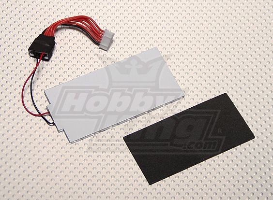
I know I'm not the first to do this on a DX6i; but all the ones I've seen pretty much just relied on Hot Glue Abuse to keep them together. While I LOVE Hot Glue for making cheap airframes out of Dollar Store Foam signboards; not so much a fan as primary engineering material. Here's what you get for your $5. The first thing we're going to do is set aside the foam for future projects; we don't need it here. Next we're going to cut the heat shrink tubing from that adapter dongle and unsolder the 2 wires leading to the LED panel. Save the dongle for future projects too. Partzes!
Blue LED Backlight Kit Purchased here: https://www.hobbyking.com/hobbyking/...arehouse_.html
1)
Initial Layout
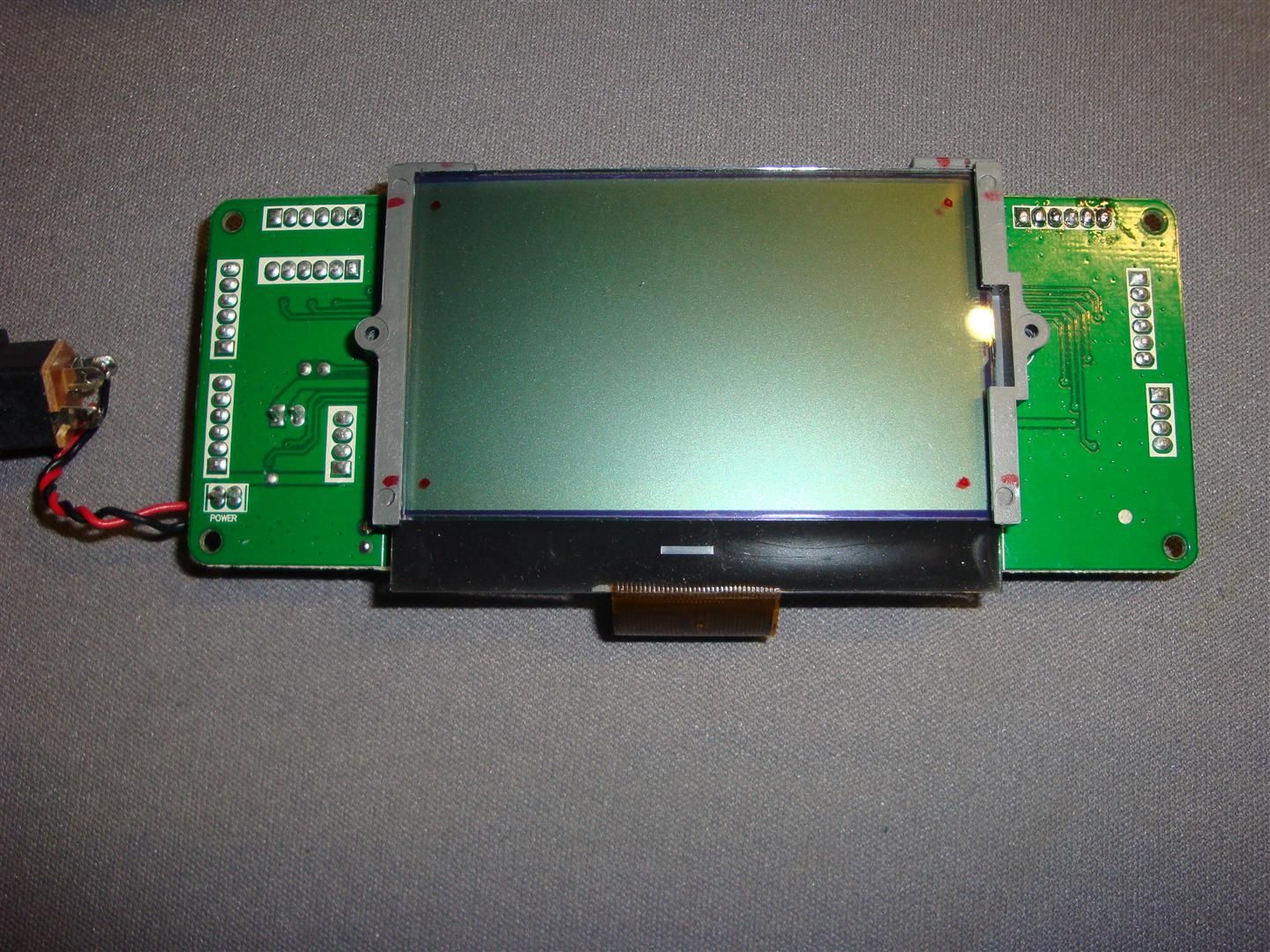
The dots mark the corners of the active portion of the dot matrix; I used this as a guide for designing required active area of the screen.
2)
First Mockup
Here we have the stock LCD brackets with no panel in place. Using this as a guide, I determined how to cut out the brackets to fit the LED panel.
3)
Trial fitting of the LED Backlight
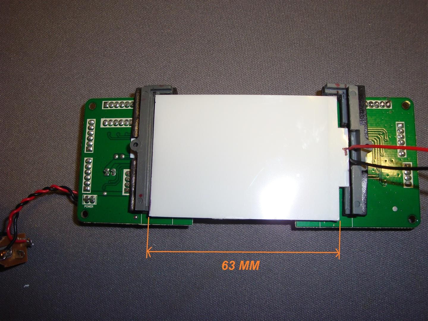
You can see here how I've trimmed the LCD brackets to accommodate the LED Backlight which has been cut to 63mm across the main body of the panel.
4) Backlight Panel Preparation
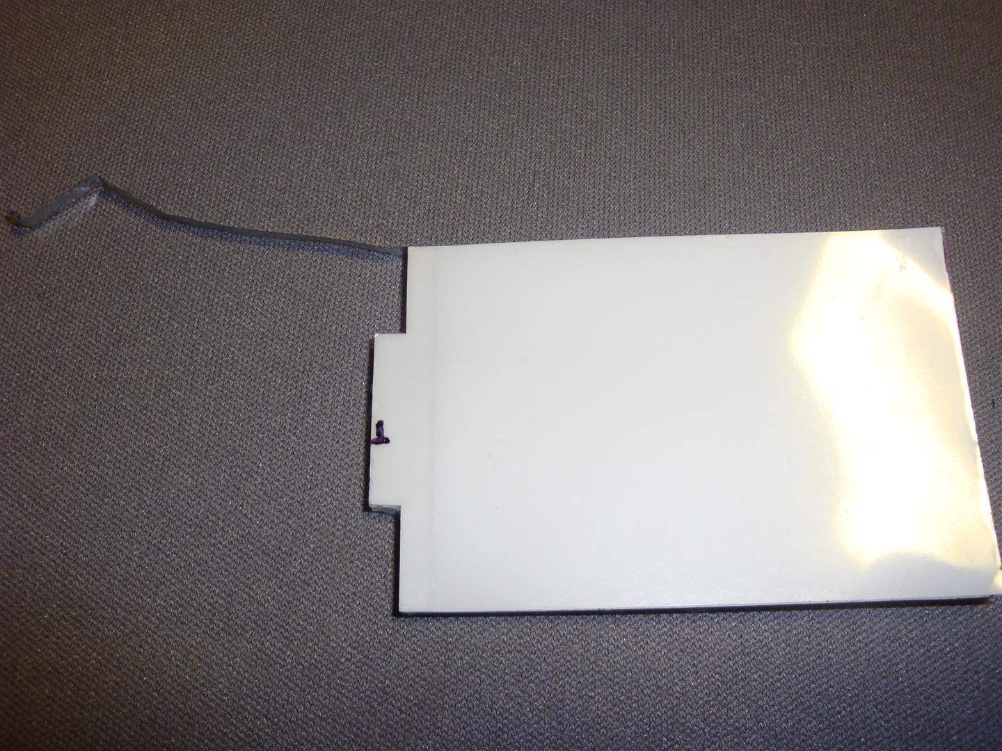
Before trimming the panel, peel this reflective tape from around the edge & save it so you can reinstall it after cutting. The panel has a translucent sheet on the top & the bottom; both which are held in place by thin strips of double-faced tape at the edges.
When cutting, lay out the cut right on those sheets, then cut them first with an X-Acto knife & peel them off. Use a Dremel with a cut-off wheel to make your cut; then scrape the slag off with the X-Acto knife.
Finally, lift the sheets and make sure there aren't any stray grains of plastic from the cut; now you can replace the reflective tape. Don't worry about the sheets only being glued down at one end; it's more than enough.
5)
Bracket Re-Engineering
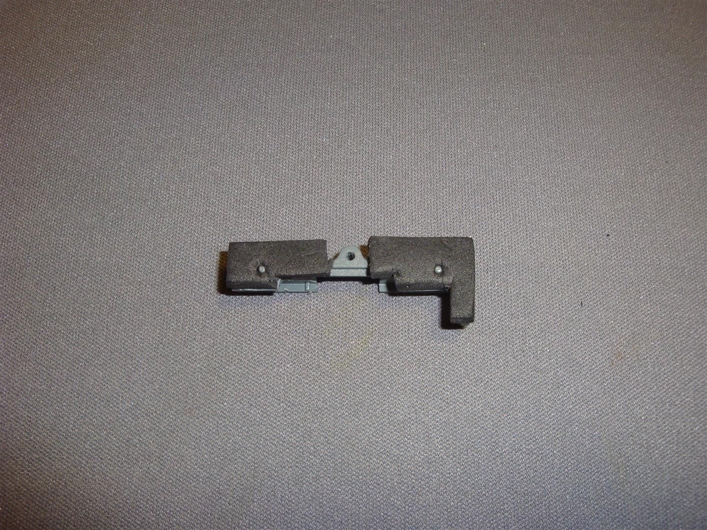
Here you can see how I cut a small relief into the bracket for the LED end of the backlight. The black adhesive-back foam is from the backlight kit; I later eliminated this in the design as it caused unacceptable warpage of the brackets rather than supporting them as intended.
6)
Critical Spacer
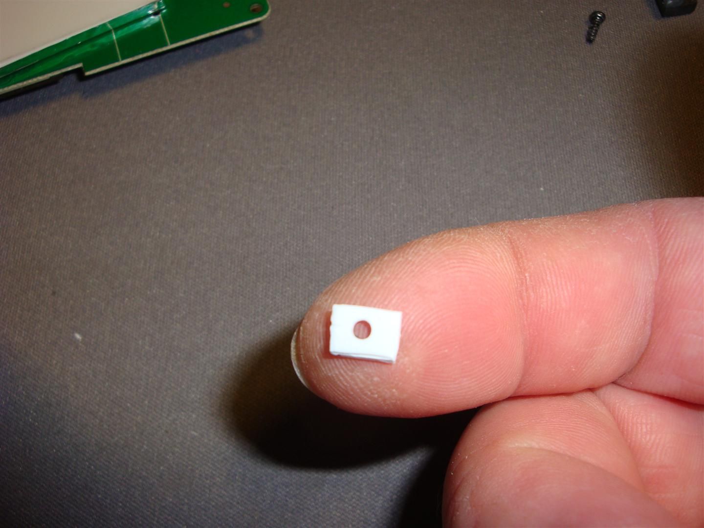
Here you can see the non-conductive spacer I made of scrap plastic from a Yogurt container; depending on the thickness of protruding solder joints under the panel, it will need to be between 1 & 2mm thick. If you don't mind shaving those tall solder joints a little with your Dremel it'll be closer to 1mm, and you won't need to worry about making similar spacers to go on the 4 screws that hold the PCB to the case of the radio. Mine were 1.1mm thick.
7)
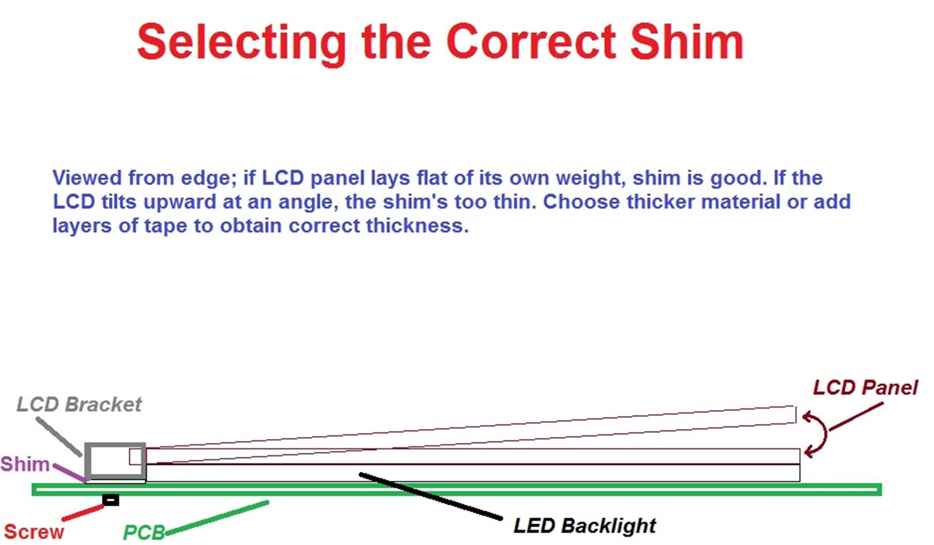
To guage needed thickness, install 1 bracket with a spacer as a trial. Place the backlight in place, then carefully slip the end of the LCD into the channel in the bracket. If it is thick enough the LCD will lay flat on the backlight panel of its own weight. If it wants to tip up as seen in the diagram, then the shim is too thin. you can easily add a few thousandths at a time to a close shim by adding layers of masking or Scotch tape. If it looks good, make another shim the same thickness and try the other side too. Be careful when tightening; you should never stop being able to move the LCD slightly in the bracket. Once you have both bracket screws tight you should be able to move the LCD slightly in the bracket, but it should have a little bit of drag.
8)
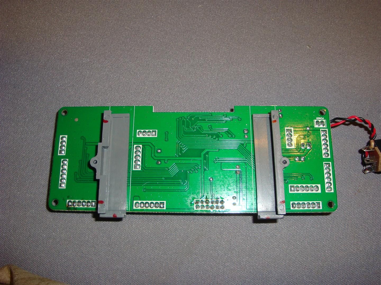
Needed Holes
First test fitting in the radio revealed that (as I suspected) there was not enough clearance to allow wires from LED to pass over bracket as seen in photo # 3. Drilling these 1/16 inch holes allows them to be routed as needed without weakening the bracket in a critical area. Notice also the chamfering to allow space for the wires.
9)
Ready for Test-Fitting
Here you can see the completed LCD with backlight & rerouted wires. Yes, that is hot glue; Spektrum put some there to make sure the LCD couldn't shift out of that thin edge of the bracket, so I put it back when I was done. A gram of prevention is worth a Kilo of fixing.
10)
The Role of Failure in Design
And here you can see my setup in its first trial fitting powered by a couple AAA batteries... not exactly fabulous due to unforeseen reflective tape under the top sheet of the backlight panel. Time to redesign.
11)
Naked Backlight
Here you can see the backlight with the top diffuser sheet removed; I've peeled off the reflective plastic & placed it so it won't make such a strange shadow behind the LCD, then trimmed off the excess. Reassembled and refit in the case; now it's looking like it should.
12)
Hook Me Up, Scotty
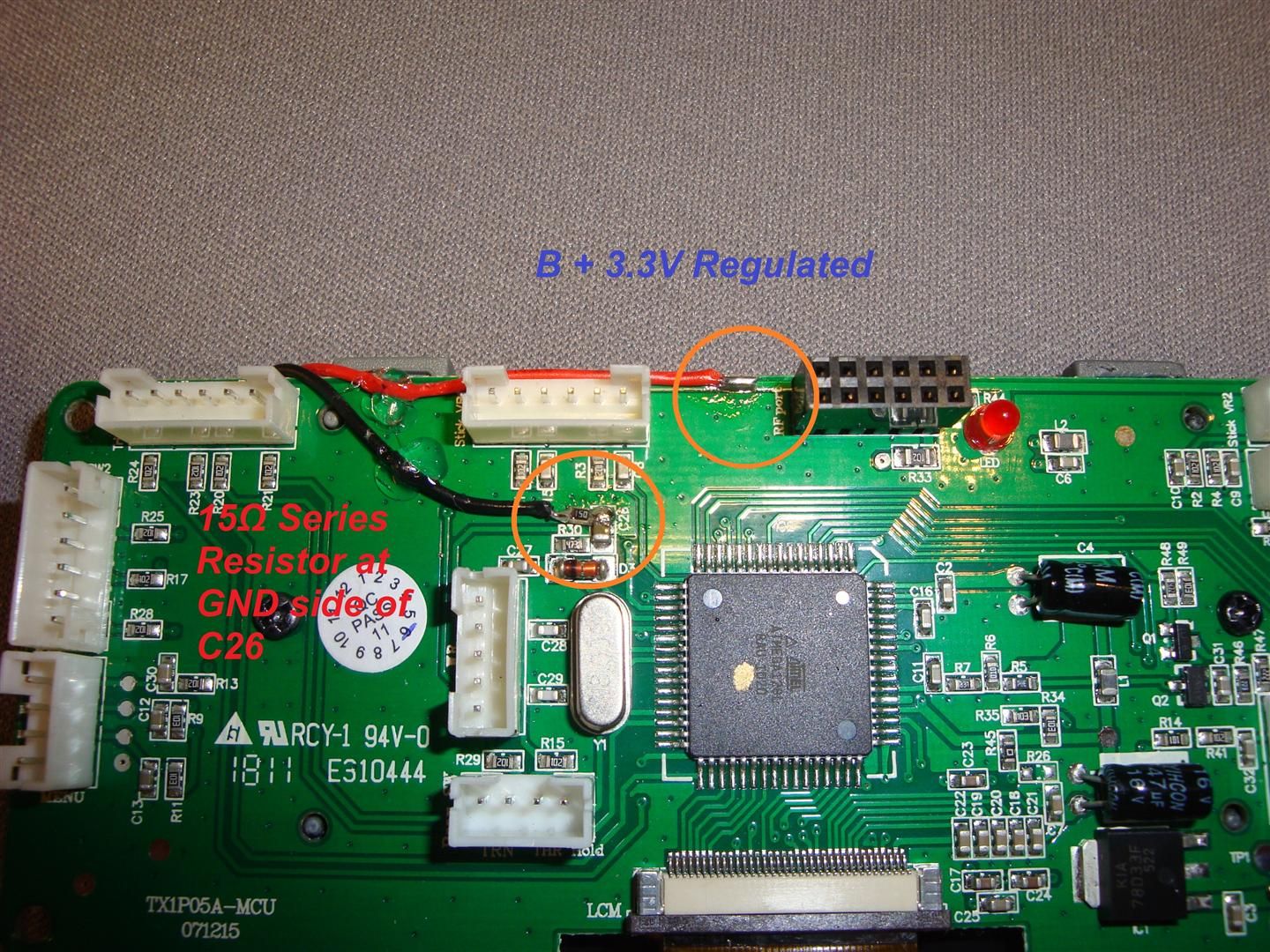
The trace across the top edge of the board where the red wire is soldered is 3.3V regulated main DC feeding pretty much the whole radio. Tapping power from here means I won't have to worry about the backlight dimming as the batteries run down.
After some trial & error using a 100Ω potentiometer, I determined that a 15Ω series resistor would give exactly the rated 20mA current draw with the 2 LED setup in the backlight. This is the optimum current for maximum brightness without shortening LED life; I just happened to find one on a scrap PCB under my bench first thing (Yes, that IS a 15Ω SMD resistor). The closest common resistor you'll find would be 22Ω; (Red, Red, Black) It'll give a load of approx 15-16mA. You probably wouldn't be able to tell the difference in brightness between the two with the naked eye. If you NEED to have Max brightness, you can take a gamble on a 10Ω series resistor; it may shorten the life of your LEDs though.
13)
Wooo! Shiny!

Completely assembled, all fitted & ready to install. This one didn't need any shims between the PCB and Radio body at the 4 mounting screws. If your PCB doesn't rest flat against the screw posts, and it's not just a wire out of place, you'll need to make 4 spacers similar to the ones used under the LCD brackets.
14)
Let There be Light!
Here it is: A much more elegant weapon from a more civilized age.
The display is nearly as bright as the backlight on my new 9XR; definitely brighter than my 2 yr-old 9X. The contrast is MUCH better than I can show with my camera; after like 20 shots all like this I gave up. Simply beautiful!
Summary:
Yes, it's a bit more work, and it requires fabricating and soldering. BUT... doing it this way has several advantages.
1) No messing about with making templates to be sure the LCD is aligned properly; you're using the original brackets, so it stays where it should be.
2) No unneeded junk; that dongle is far more useful as a spare balance cable than displacing air inside your TX.
3) Using the 3.3V feed is inherently more efficient, plus it lets you use the short wires already on the LED backlight panel.
4) Using a regulated DC power source means the LCD stays at the same brightness throughout the life of the batteries. You can actually see the meter when the alarms go off!
5) Spare Parts; We've all spent $5 on a Balancer Cable. Well, now you've got another, which means this backlight was FREE!
6) You just proved you can do it as well as the guys at Spektrum; if not better.
Hope you find this useful; I know the DX6i is not as hot a model as it once was, but I think it's still worth spending a little time on doing it right.
mnem
Keep on defying gravity; it needs to be shown a thing or two!
I know I'm not the first to do this on a DX6i; but all the ones I've seen pretty much just relied on Hot Glue Abuse to keep them together. While I LOVE Hot Glue for making cheap airframes out of Dollar Store Foam signboards; not so much a fan as primary engineering material. Here's what you get for your $5. The first thing we're going to do is set aside the foam for future projects; we don't need it here. Next we're going to cut the heat shrink tubing from that adapter dongle and unsolder the 2 wires leading to the LED panel. Save the dongle for future projects too. Partzes!
Blue LED Backlight Kit Purchased here: https://www.hobbyking.com/hobbyking/...arehouse_.html
1)
Initial Layout
The dots mark the corners of the active portion of the dot matrix; I used this as a guide for designing required active area of the screen.
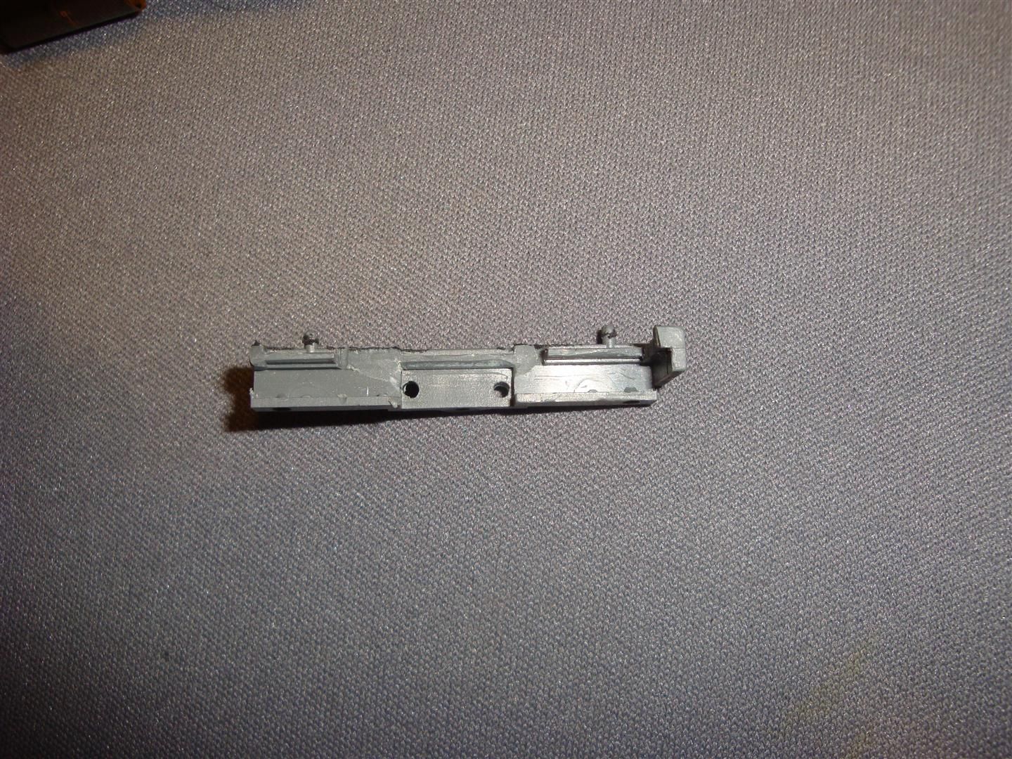
2)
First Mockup
Here we have the stock LCD brackets with no panel in place. Using this as a guide, I determined how to cut out the brackets to fit the LED panel.
3)
Trial fitting of the LED Backlight
You can see here how I've trimmed the LCD brackets to accommodate the LED Backlight which has been cut to 63mm across the main body of the panel.
4) Backlight Panel Preparation
Before trimming the panel, peel this reflective tape from around the edge & save it so you can reinstall it after cutting. The panel has a translucent sheet on the top & the bottom; both which are held in place by thin strips of double-faced tape at the edges.
When cutting, lay out the cut right on those sheets, then cut them first with an X-Acto knife & peel them off. Use a Dremel with a cut-off wheel to make your cut; then scrape the slag off with the X-Acto knife.
Finally, lift the sheets and make sure there aren't any stray grains of plastic from the cut; now you can replace the reflective tape. Don't worry about the sheets only being glued down at one end; it's more than enough.
5)
Bracket Re-Engineering
Here you can see how I cut a small relief into the bracket for the LED end of the backlight. The black adhesive-back foam is from the backlight kit; I later eliminated this in the design as it caused unacceptable warpage of the brackets rather than supporting them as intended.
6)
Critical Spacer
Here you can see the non-conductive spacer I made of scrap plastic from a Yogurt container; depending on the thickness of protruding solder joints under the panel, it will need to be between 1 & 2mm thick. If you don't mind shaving those tall solder joints a little with your Dremel it'll be closer to 1mm, and you won't need to worry about making similar spacers to go on the 4 screws that hold the PCB to the case of the radio. Mine were 1.1mm thick.
7)
To guage needed thickness, install 1 bracket with a spacer as a trial. Place the backlight in place, then carefully slip the end of the LCD into the channel in the bracket. If it is thick enough the LCD will lay flat on the backlight panel of its own weight. If it wants to tip up as seen in the diagram, then the shim is too thin. you can easily add a few thousandths at a time to a close shim by adding layers of masking or Scotch tape. If it looks good, make another shim the same thickness and try the other side too. Be careful when tightening; you should never stop being able to move the LCD slightly in the bracket. Once you have both bracket screws tight you should be able to move the LCD slightly in the bracket, but it should have a little bit of drag.
8)
Needed Holes
First test fitting in the radio revealed that (as I suspected) there was not enough clearance to allow wires from LED to pass over bracket as seen in photo # 3. Drilling these 1/16 inch holes allows them to be routed as needed without weakening the bracket in a critical area. Notice also the chamfering to allow space for the wires.
9)
Ready for Test-Fitting
Here you can see the completed LCD with backlight & rerouted wires. Yes, that is hot glue; Spektrum put some there to make sure the LCD couldn't shift out of that thin edge of the bracket, so I put it back when I was done. A gram of prevention is worth a Kilo of fixing.
10)
The Role of Failure in Design
And here you can see my setup in its first trial fitting powered by a couple AAA batteries... not exactly fabulous due to unforeseen reflective tape under the top sheet of the backlight panel. Time to redesign.
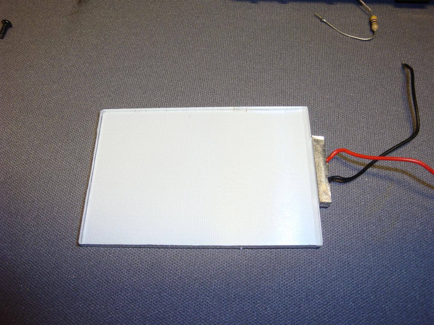
11)
Naked Backlight
Here you can see the backlight with the top diffuser sheet removed; I've peeled off the reflective plastic & placed it so it won't make such a strange shadow behind the LCD, then trimmed off the excess. Reassembled and refit in the case; now it's looking like it should.
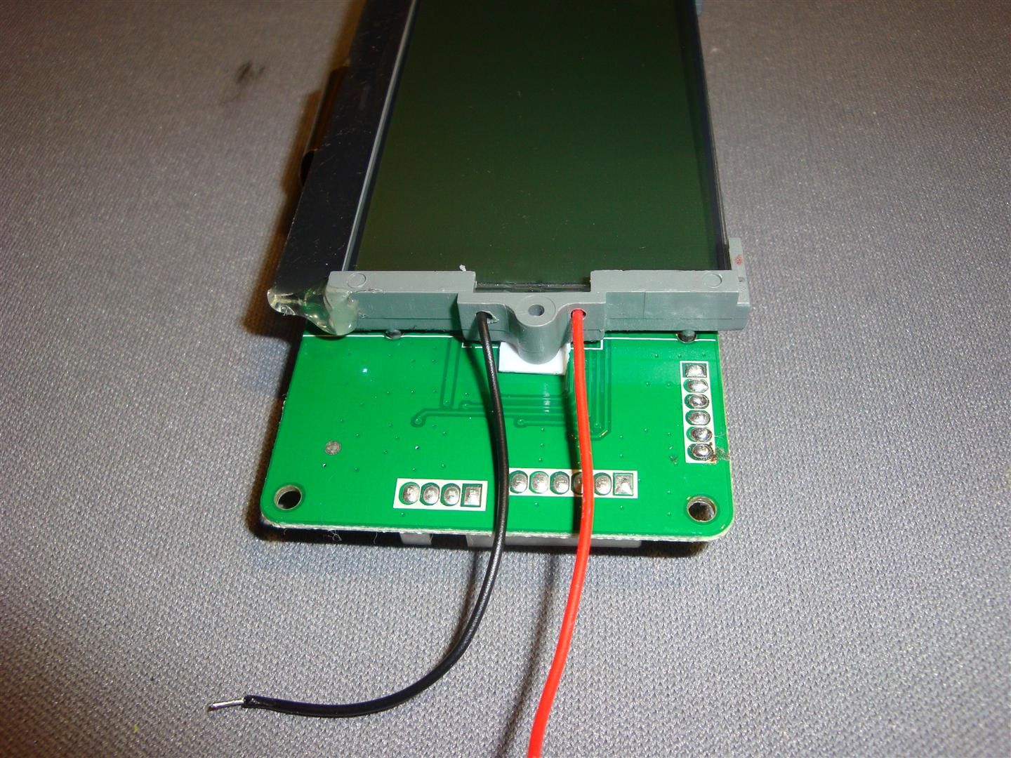
12)
Hook Me Up, Scotty
The trace across the top edge of the board where the red wire is soldered is 3.3V regulated main DC feeding pretty much the whole radio. Tapping power from here means I won't have to worry about the backlight dimming as the batteries run down.
After some trial & error using a 100Ω potentiometer, I determined that a 15Ω series resistor would give exactly the rated 20mA current draw with the 2 LED setup in the backlight. This is the optimum current for maximum brightness without shortening LED life; I just happened to find one on a scrap PCB under my bench first thing (Yes, that IS a 15Ω SMD resistor). The closest common resistor you'll find would be 22Ω; (Red, Red, Black) It'll give a load of approx 15-16mA. You probably wouldn't be able to tell the difference in brightness between the two with the naked eye. If you NEED to have Max brightness, you can take a gamble on a 10Ω series resistor; it may shorten the life of your LEDs though.
13)
Wooo! Shiny!
Completely assembled, all fitted & ready to install. This one didn't need any shims between the PCB and Radio body at the 4 mounting screws. If your PCB doesn't rest flat against the screw posts, and it's not just a wire out of place, you'll need to make 4 spacers similar to the ones used under the LCD brackets.
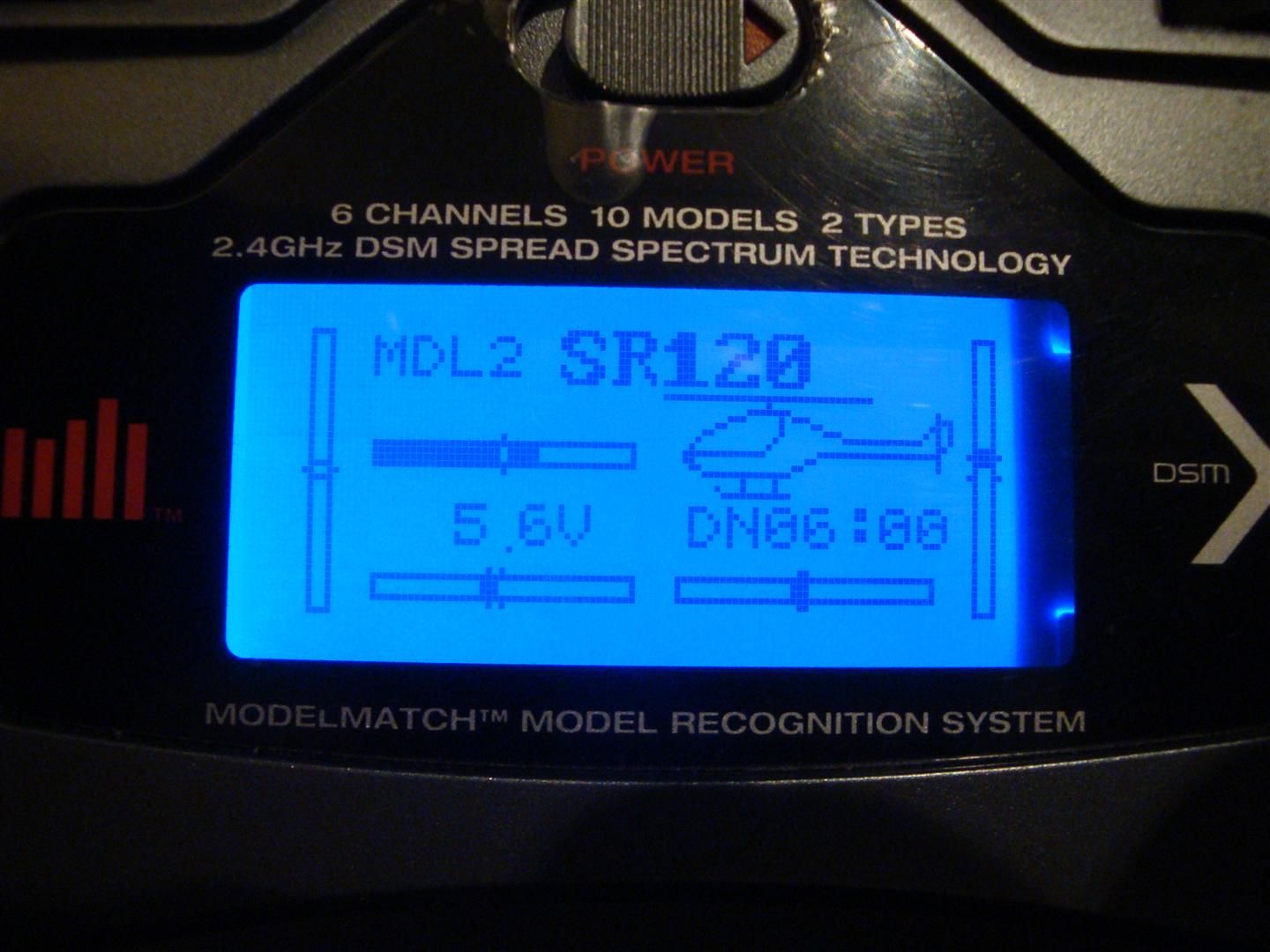
14)
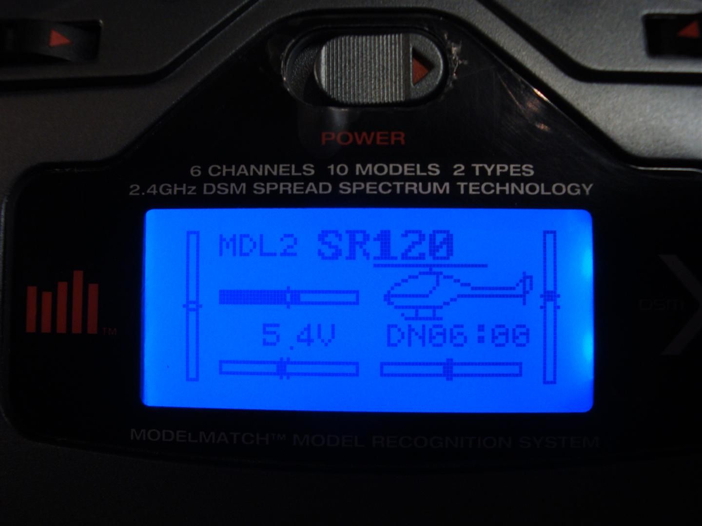
Let There be Light!
Here it is: A much more elegant weapon from a more civilized age.
The display is nearly as bright as the backlight on my new 9XR; definitely brighter than my 2 yr-old 9X. The contrast is MUCH better than I can show with my camera; after like 20 shots all like this I gave up. Simply beautiful!
Summary:
Yes, it's a bit more work, and it requires fabricating and soldering. BUT... doing it this way has several advantages.
1) No messing about with making templates to be sure the LCD is aligned properly; you're using the original brackets, so it stays where it should be.
2) No unneeded junk; that dongle is far more useful as a spare balance cable than displacing air inside your TX.
3) Using the 3.3V feed is inherently more efficient, plus it lets you use the short wires already on the LED backlight panel.
4) Using a regulated DC power source means the LCD stays at the same brightness throughout the life of the batteries. You can actually see the meter when the alarms go off!
5) Spare Parts; We've all spent $5 on a Balancer Cable. Well, now you've got another, which means this backlight was FREE!
6) You just proved you can do it as well as the guys at Spektrum; if not better.
Hope you find this useful; I know the DX6i is not as hot a model as it once was, but I think it's still worth spending a little time on doing it right.
mnem
Keep on defying gravity; it needs to be shown a thing or two!
 11-10-2020, 03:25 PM
#3
Junior Member
Did mine today. I pulled power from the switch through the pcb. Using my LED Backlite tester, I determined either method still netted the LED's pulling 2.6VDC, so it was easier to just pick up the power off the switch, and I did not have any resistors to use for the 3.3vdc source anyway. . I also depinned the connector and un-soldered everything off the PCB, no need to cut when it can be depinned easily, and I had to solder anyway.
It was more work, but it really comes out clean, and its serviceable! Which for turns out to be a good thing since I fumble fingered the LCD and dropped it on my tile floor, and now it has a dead row .... Alliexpress to the rescue, and new one will be here eventually for $15 shipped.
Thanks again mnemennth for the idea! I can see my display now!
