


Building the Carina from scratch
 04-07-2015, 11:45 PM
#1
Junior Member
Thread Starter
Join Date: Apr 2015
Posts: 11
Likes: 0
Received 0 Likes
on
0 Posts
Dear friends
as promised or may better said as I have threatened to do, here the report of my eternal build from scratch of a sailboat with long keel based on the plan of the Voilier from a German source. The plan is the copy of a copy of a copy and as such distortions of it have made it necessary to do a lot of rework on the plan to be able to use it. I was quite disappointed when I got delivered the plan that did not consist of more than a DIN A0 sized paper.

This plan used to build the Carina is even in worse shape, as I did not care enough of it when I build the first hull using this plan the sail boat called the Sabrina. Then my son Andreas had to embarque into a school work in its 8th class and so he accepted my offer to build a hull based on this plan. For me the intention was to build a light version of the sail boat, as the first resulted too ambitious.

So the first step in this project for my son was to digitize the frames of the plan and the top and side views. For this he started with good old fashion technique using oil, to make the paper of the plan transparent and a needle and pass the shapes onto coordinate paper.
We used the Excel Chart feature, were the previously recorded digitized values were stored to fix the values that were evidently wrong. A nice side effect of this was, that errors while digitizing the data became evident and could be corrected.
Having done this we used the result to fix distorsions and to ensure the curves were smooth. Then we passes the frames into a CAD package you can get for free, called "Solid Edge 2G Drafting". Here an example:
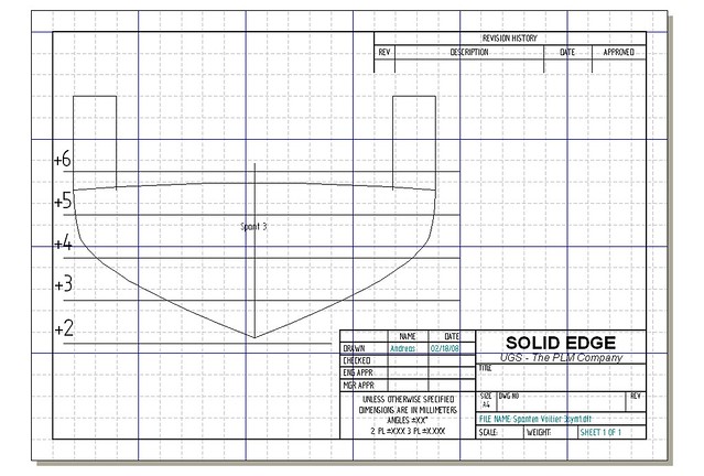
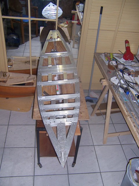
You can see that we added "ears" to the frames. The reason for this is that we choose the the upside down method of building the hull and all frames had to be placed at such altitude above the base, that the design waterline had to on a horizontal plane parallel to the base.
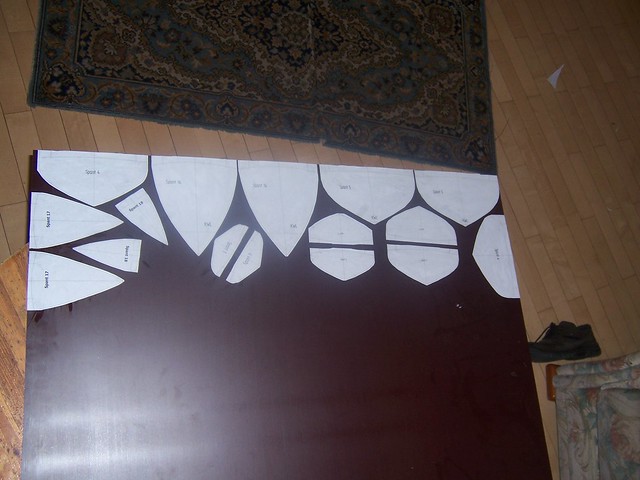
We than printed the frame images and glued them onto a 4 mm thick wooden plate. I want to indicate, that heavy paper or even better, carton should be used, as normal 80 gr. paper tends to change its shape, when the glue is applied, as it gets wet. This wooden plate used is called "Siebdruckplatte" in German. This king of wooden plate is used to build concrete formwork. It has the advantage to have a surface that is very resistant to mechanical and chemical stress, here the advantage is that it is very brittle. You will see later why this is of huge benefit!
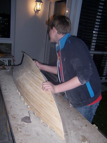
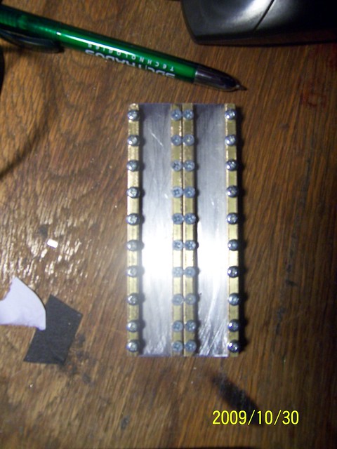
As you might see looking in detail into the foto, I used the zip-principle to glue the ridges onto the frames, 8 x 3 mm cross section.
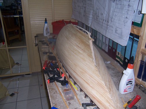
To ensure the hull would not be distorted during the construction, we glued the ridges, one at each side, making sure the stress would stay symmetrical.
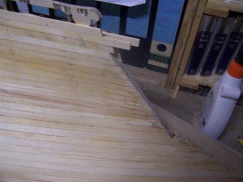
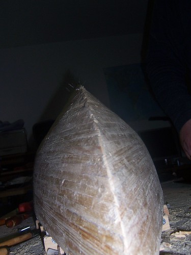
When I build my first hull I was worried about how easy or difficult the glueing of the ridges would be, specially at places like the one shown in the picture, were different shapes come together. But it proved to be no problem. The most difficult one was glueing the second ridge after the one following the deckline next to the stern mirror. The first ridge following the deckline had to be glued vertically, the second hat to follow the large change of the frame shape.
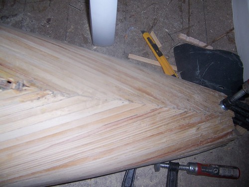
The reason I used pine wood for the ridges, was the grain of the wood. I want to highlight the old wisdom of anyone familiar with handcraft work, that any error that can be fixed early in the work process saves from having to spend 10x the effort to fix it later! So spending effort to get perfectly shaped frames is well spend to save work while grinding. my son had the great idea of taking some images from within the hull to make the construction visible. Next some pictures made from within the hull!

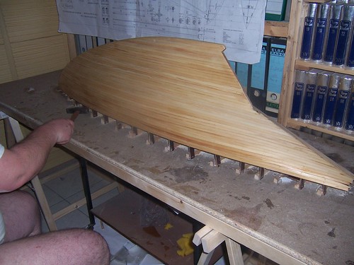
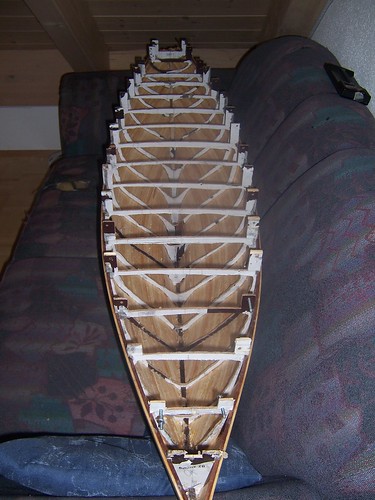
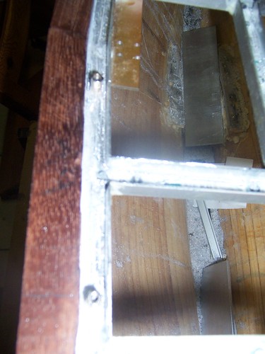
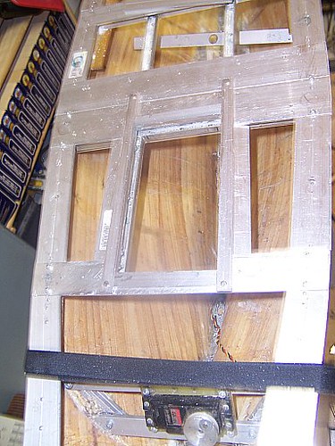
I love this picture as it shows the frames and the ridges glued to them. But also interesting has proven to be the fact that even the filigran shape of the frames was OK and it facilitates the pressing of the ridges onto the frames while glueing them.
Now a picture from the grinding phase of the construction of the hull.
While no doubt it is a tough job, it is also honouring it with the results! excuse me if you consider it not appropriate. But sliding the hand surface of such a wooden hull after some grinding gives a wonderful feeling, some consider as great as doing the same with a woman! Wood is a wonderful material to work with! To motivate myself grinding, I like to proceed, changing from grinding one side until it feels pretty good and than change sides. The result is, that the actual side being grinded at the end feels so much better, that you end up really wishing to improve the other side! Grinding of the hull took nearly 3 weeks!
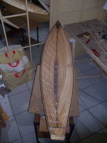
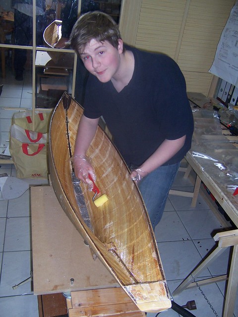
When the grinding has reached a quality of the surface that seems fine, I like to apply G8 polyurethane varnish, with thinner, using 4 parts of thinner and one part of the varnish. One one side this varnish has the effect to protect the wood from humidity that might come in touch with it if the lamination gets damaged, but in this phase of grinding the hull it has the effect of improving the light reflection of the surface of the hull making irregularities visible.
Remember, I cannot use filler, as i want to keep the grain of the pine wood visible. On the picture you see me working on removing the hull from the base. The frame had been fixed to the bars screwed onto the base, but the glue falling onto it while glueing the ridges onto the frame, made it necessary to use a tool to remove the frames. You can also see how the G8 has changed the color of the ridges, while this is also a prove that the wood is well protected against humidity, as the thinner helps the G8 varnish to penetrate deep into the wood.
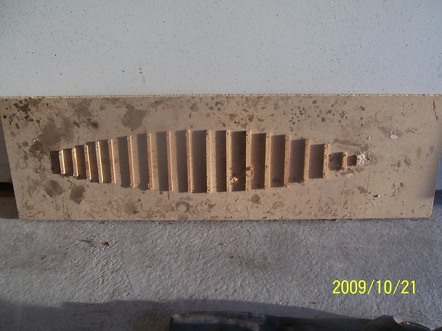
Here a picture of the base showing the principle of how I fixed the frames onto it. The planarity of the base is key, as any distortion would pass onto the hull shape being build. So I use the thickest wooden plate available and do reinforce it applying stabilizing wooden frame at the length on both sides.
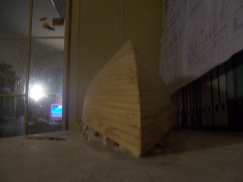
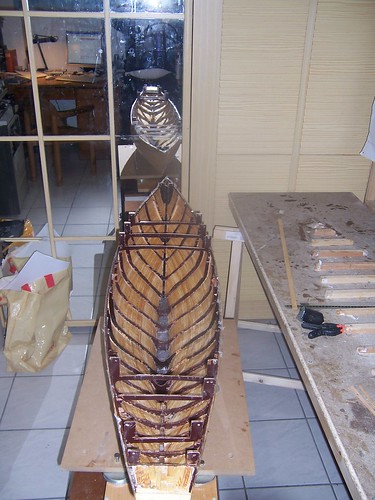
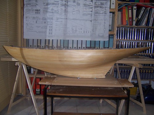
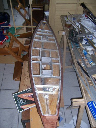
Here a view from the to�p of the whole hull, just after removing it from the base. You can see, that the frame are already implementing the curvature of the deck, a useless effort, as the frames broke easily due to the brittle nature of the wood used! The weight of this 165 cm long hull was just about 450 gr, including the frames!
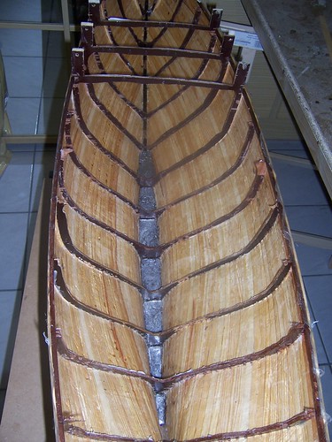
Here you can see how the frames got spoiled over time. But this apparently weakness proved to be marvelous! As the frames were so brittle, removing them, just using a tong, grasping a piece of the frame and turning the tong. This way the frames could be removed leaving nearly no trace on the hull!
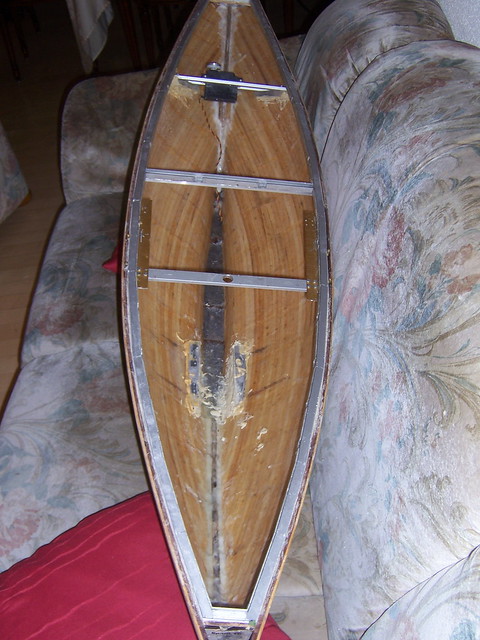
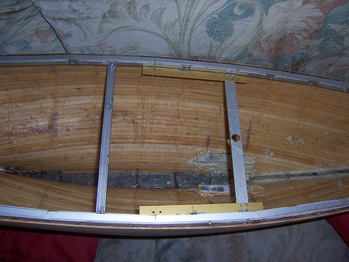
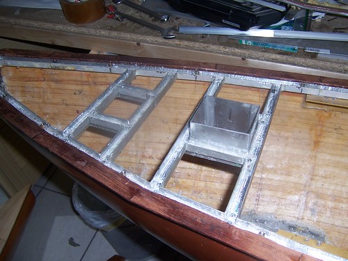
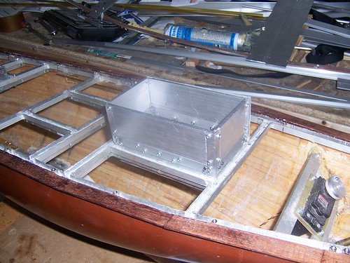
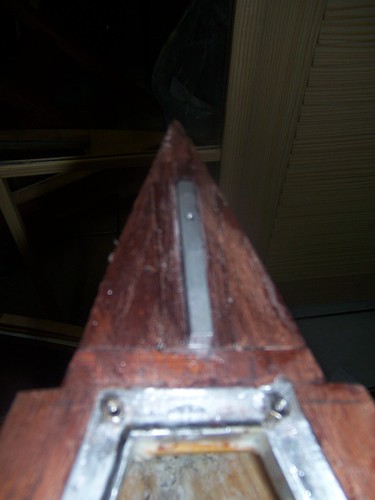
Isn't this a great result? Such a clean inner side of the hull, that just required a bit of grinding, would make it much easier to laminate the hull from within. But it also reduced the weight. of course I did also apply a few layers of G8 varnish to the inner side to make sure the wood was well protected against humidity! But there are 2 more things I would like to highlight in this picture. One being the fact that I did fill up the front most and the rear most compartment made by the frame with epoxy. And that I did insert at this phase only in the front an aluminium piece in it where the screwed hole was prepared to connect the fixing point of the mast. This way that pont was firmly integrated into the hull structure. later same was done at the rear.
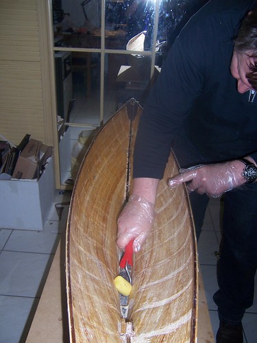
The second point I want to highlight is the lead I am casting into the bottom of the keel. The technique used and that prevents the wooden ridges to suffer from that process is as follows. Fist i just cast a bit into the hull and let it cool. The amount of heat energy of just a bit lead is not enough to endanger the wood. Then, as i add more lead, the already present lead works a a heat sink, absorbing the lead of the later one applied, so that on every step more and more lead can be casted into the hull without damaging the wood.
Here a more detailed view of this.
remember, that on a sail boat with long keel every effort has to be done to have the center of gravity as deep in the hull as possible. Just let me tell you, that the final displacement of the hull allows for a total weight of the sail boat of 29 kgs!
Here you see me laminating the hull with glas fiber and epoxy from within. it is important to mention, that as wood works, to prevent this from making the ridges noticeable when touching the hull from outside, symmetrical lamination from the inner and the external side of the hull is mandatory. i have used 29 grs per square meter weight glas fiber for the lamination, but up to about 100 grs is OK, and you would not see or feel the lamination when touching the hull!
Here the compensation for all those efforts! i sometimes think it would make sense to leave the hull like this, as the color is to my personal o�pinion marvelous! I want to stop here the report to reflect the achievement reached at this point and continue the report as a reply to this contribution!
as promised or may better said as I have threatened to do, here the report of my eternal build from scratch of a sailboat with long keel based on the plan of the Voilier from a German source. The plan is the copy of a copy of a copy and as such distortions of it have made it necessary to do a lot of rework on the plan to be able to use it. I was quite disappointed when I got delivered the plan that did not consist of more than a DIN A0 sized paper.
This plan used to build the Carina is even in worse shape, as I did not care enough of it when I build the first hull using this plan the sail boat called the Sabrina. Then my son Andreas had to embarque into a school work in its 8th class and so he accepted my offer to build a hull based on this plan. For me the intention was to build a light version of the sail boat, as the first resulted too ambitious.
So the first step in this project for my son was to digitize the frames of the plan and the top and side views. For this he started with good old fashion technique using oil, to make the paper of the plan transparent and a needle and pass the shapes onto coordinate paper.
We used the Excel Chart feature, were the previously recorded digitized values were stored to fix the values that were evidently wrong. A nice side effect of this was, that errors while digitizing the data became evident and could be corrected.
Having done this we used the result to fix distorsions and to ensure the curves were smooth. Then we passes the frames into a CAD package you can get for free, called "Solid Edge 2G Drafting". Here an example:
You can see that we added "ears" to the frames. The reason for this is that we choose the the upside down method of building the hull and all frames had to be placed at such altitude above the base, that the design waterline had to on a horizontal plane parallel to the base.
We than printed the frame images and glued them onto a 4 mm thick wooden plate. I want to indicate, that heavy paper or even better, carton should be used, as normal 80 gr. paper tends to change its shape, when the glue is applied, as it gets wet. This wooden plate used is called "Siebdruckplatte" in German. This king of wooden plate is used to build concrete formwork. It has the advantage to have a surface that is very resistant to mechanical and chemical stress, here the advantage is that it is very brittle. You will see later why this is of huge benefit!
As you might see looking in detail into the foto, I used the zip-principle to glue the ridges onto the frames, 8 x 3 mm cross section.
To ensure the hull would not be distorted during the construction, we glued the ridges, one at each side, making sure the stress would stay symmetrical.
When I build my first hull I was worried about how easy or difficult the glueing of the ridges would be, specially at places like the one shown in the picture, were different shapes come together. But it proved to be no problem. The most difficult one was glueing the second ridge after the one following the deckline next to the stern mirror. The first ridge following the deckline had to be glued vertically, the second hat to follow the large change of the frame shape.
The reason I used pine wood for the ridges, was the grain of the wood. I want to highlight the old wisdom of anyone familiar with handcraft work, that any error that can be fixed early in the work process saves from having to spend 10x the effort to fix it later! So spending effort to get perfectly shaped frames is well spend to save work while grinding. my son had the great idea of taking some images from within the hull to make the construction visible. Next some pictures made from within the hull!
I love this picture as it shows the frames and the ridges glued to them. But also interesting has proven to be the fact that even the filigran shape of the frames was OK and it facilitates the pressing of the ridges onto the frames while glueing them.
Now a picture from the grinding phase of the construction of the hull.
While no doubt it is a tough job, it is also honouring it with the results! excuse me if you consider it not appropriate. But sliding the hand surface of such a wooden hull after some grinding gives a wonderful feeling, some consider as great as doing the same with a woman! Wood is a wonderful material to work with! To motivate myself grinding, I like to proceed, changing from grinding one side until it feels pretty good and than change sides. The result is, that the actual side being grinded at the end feels so much better, that you end up really wishing to improve the other side! Grinding of the hull took nearly 3 weeks!
When the grinding has reached a quality of the surface that seems fine, I like to apply G8 polyurethane varnish, with thinner, using 4 parts of thinner and one part of the varnish. One one side this varnish has the effect to protect the wood from humidity that might come in touch with it if the lamination gets damaged, but in this phase of grinding the hull it has the effect of improving the light reflection of the surface of the hull making irregularities visible.
Remember, I cannot use filler, as i want to keep the grain of the pine wood visible. On the picture you see me working on removing the hull from the base. The frame had been fixed to the bars screwed onto the base, but the glue falling onto it while glueing the ridges onto the frame, made it necessary to use a tool to remove the frames. You can also see how the G8 has changed the color of the ridges, while this is also a prove that the wood is well protected against humidity, as the thinner helps the G8 varnish to penetrate deep into the wood.
Here a picture of the base showing the principle of how I fixed the frames onto it. The planarity of the base is key, as any distortion would pass onto the hull shape being build. So I use the thickest wooden plate available and do reinforce it applying stabilizing wooden frame at the length on both sides.
Here a view from the to�p of the whole hull, just after removing it from the base. You can see, that the frame are already implementing the curvature of the deck, a useless effort, as the frames broke easily due to the brittle nature of the wood used! The weight of this 165 cm long hull was just about 450 gr, including the frames!
Here you can see how the frames got spoiled over time. But this apparently weakness proved to be marvelous! As the frames were so brittle, removing them, just using a tong, grasping a piece of the frame and turning the tong. This way the frames could be removed leaving nearly no trace on the hull!
Isn't this a great result? Such a clean inner side of the hull, that just required a bit of grinding, would make it much easier to laminate the hull from within. But it also reduced the weight. of course I did also apply a few layers of G8 varnish to the inner side to make sure the wood was well protected against humidity! But there are 2 more things I would like to highlight in this picture. One being the fact that I did fill up the front most and the rear most compartment made by the frame with epoxy. And that I did insert at this phase only in the front an aluminium piece in it where the screwed hole was prepared to connect the fixing point of the mast. This way that pont was firmly integrated into the hull structure. later same was done at the rear.
The second point I want to highlight is the lead I am casting into the bottom of the keel. The technique used and that prevents the wooden ridges to suffer from that process is as follows. Fist i just cast a bit into the hull and let it cool. The amount of heat energy of just a bit lead is not enough to endanger the wood. Then, as i add more lead, the already present lead works a a heat sink, absorbing the lead of the later one applied, so that on every step more and more lead can be casted into the hull without damaging the wood.
Here a more detailed view of this.
remember, that on a sail boat with long keel every effort has to be done to have the center of gravity as deep in the hull as possible. Just let me tell you, that the final displacement of the hull allows for a total weight of the sail boat of 29 kgs!
Here you see me laminating the hull with glas fiber and epoxy from within. it is important to mention, that as wood works, to prevent this from making the ridges noticeable when touching the hull from outside, symmetrical lamination from the inner and the external side of the hull is mandatory. i have used 29 grs per square meter weight glas fiber for the lamination, but up to about 100 grs is OK, and you would not see or feel the lamination when touching the hull!
Here the compensation for all those efforts! i sometimes think it would make sense to leave the hull like this, as the color is to my personal o�pinion marvelous! I want to stop here the report to reflect the achievement reached at this point and continue the report as a reply to this contribution!
 04-07-2015, 11:47 PM
#2
Junior Member
Thread Starter
Join Date: Apr 2015
Posts: 11
Likes: 0
Received 0 Likes
on
0 Posts
I will continue now with the report!
Sometimes small issues have great consequences! My wife, even as she is totally not technical, did ask me why I didn't make the complete deck removable. as usual, going out into the countryside with my dog I started to think about it and decided to make the complete deck removable. Now I am, what germans call the belt and suspender person. i want to make sure I am on the safe side and so I developed my concept to make sure no water would come into my hull! So I decided to combine 3 elements:
1. A labyrinth sealing made out of of two nested aluminium U-Profiles
2. A mechanical fence where ever possible
3. A rubber sealing

Lets started recapitulating the starting condition! A 5x5 mm mahogany strip follows the deckline of the hull. Along this one, fully around the hole deckline of the hull a U-Profile, made out of aluminium had to be glued into the hull, open to the top to receive water that might slip through the external rubber sealing not yet installed.
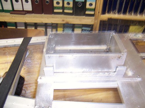
Watching this picture you can see the complete ring of aluminium glued into the hull. This definitely will stabilize the hull shape and make it extremely stable. You can also see at the rear end, on the top of this picture the mounting of a large Hitec servo to operate the rudder. Well, as of today, I plan to replace it by a small stepper motor and a large belt pulley, because this way I have more torque and it will operate without making any noise! To both sides in the middle section you can see brass colores L-profile aluminium bar screwed to an about 25 cm x 5 cm x 5 mm aluminium bar which was glued against the wooden hull. On the upper side I did make 2 threaded holes, M3, as the basis to have the pulling force from the shrouds conducted into the hull structure. I have put a bar between both sides with the hole for the mast, having its position well defined this way, based on the plan of the ship! But you can see one more very important thing, the first crossing section of the labyrinth sealing with 2 opening already made. by the plan the deck has 4 structures on the deck. These 4 structures will also be removable and so the labyrinth sealing also has to circle them!
A more detailed picture of the central section! Here I want to highlight, that because no glue did really work all connection of aluminium parts are made using screws to support the union of the parts connected also by glue, because the glue also helped to seal those unions! At the bottom you can see 2 aluminium bars glued into the bottom of the hull. Well the left overs over solutions thought of earlier and later replaced by what I do consider better approaches. here a view from the rear:

Now a total view of the labyrinth sealing nearly completed, the hull side of it, with one of the deck structures plugged into its opening!
You can also appreciate how I was continuing the work to improve the contact surfaces outside the aluminium ring, where a rubber sealing band glued onto it and the deck pressed against it, will be the first line of defense against water entering the hull this way!
A detailed photo of the front section, also with one deck structure plugged into the corresponding opening. the same for the rear section:
Now a detailed photo of the front of the hull with the aluminium bar and the threaded holes into it to connect the fixing point for the Forestay and the screw to press the deck onto the hull contact surface to make the rubber sealing work!

The same for the backstay. The surface will still be covered with veneer of mahogany wood.
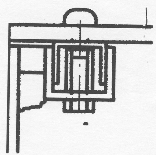
Next a detailed picture of the contact surface on the left middle side. You can see another of those techniques that proved to be inadequate, to press the deck onto the contact surface of the hull. I did plan to use and did install those hexagonal spacers we all know from our PC case used to mount the motherboard. I thought that by embedding their base into glue this would prevent those spacers from rotating. Reality proved, that some did rotate anyhow, so I had to drill the screws out to remove the mounted deck. Now, where the surface of the deck was not yet build, that was not a problem, but i will show later that I came up with a different solution.
Similar detail from the bow section:
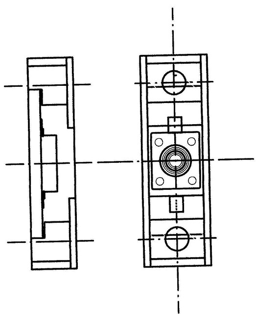
Now the picture of a drawing that shows how those spacers fit into the concept of pressing the deck onto the hull!
Finally a picture that shows the central section of the removable deck and how it will be pressed onto the hull. Just 1/3 of the width of this mahogany strip will be left when sanded to match the hull surface below! The rubber sealing will be glued where the aluminium from the deck makes contact with the surface of the hull. As I wrote before, my first line of defense against water penetrating the hull!
Sometimes small issues have great consequences! My wife, even as she is totally not technical, did ask me why I didn't make the complete deck removable. as usual, going out into the countryside with my dog I started to think about it and decided to make the complete deck removable. Now I am, what germans call the belt and suspender person. i want to make sure I am on the safe side and so I developed my concept to make sure no water would come into my hull! So I decided to combine 3 elements:
1. A labyrinth sealing made out of of two nested aluminium U-Profiles
2. A mechanical fence where ever possible
3. A rubber sealing
Lets started recapitulating the starting condition! A 5x5 mm mahogany strip follows the deckline of the hull. Along this one, fully around the hole deckline of the hull a U-Profile, made out of aluminium had to be glued into the hull, open to the top to receive water that might slip through the external rubber sealing not yet installed.
Watching this picture you can see the complete ring of aluminium glued into the hull. This definitely will stabilize the hull shape and make it extremely stable. You can also see at the rear end, on the top of this picture the mounting of a large Hitec servo to operate the rudder. Well, as of today, I plan to replace it by a small stepper motor and a large belt pulley, because this way I have more torque and it will operate without making any noise! To both sides in the middle section you can see brass colores L-profile aluminium bar screwed to an about 25 cm x 5 cm x 5 mm aluminium bar which was glued against the wooden hull. On the upper side I did make 2 threaded holes, M3, as the basis to have the pulling force from the shrouds conducted into the hull structure. I have put a bar between both sides with the hole for the mast, having its position well defined this way, based on the plan of the ship! But you can see one more very important thing, the first crossing section of the labyrinth sealing with 2 opening already made. by the plan the deck has 4 structures on the deck. These 4 structures will also be removable and so the labyrinth sealing also has to circle them!
A more detailed picture of the central section! Here I want to highlight, that because no glue did really work all connection of aluminium parts are made using screws to support the union of the parts connected also by glue, because the glue also helped to seal those unions! At the bottom you can see 2 aluminium bars glued into the bottom of the hull. Well the left overs over solutions thought of earlier and later replaced by what I do consider better approaches. here a view from the rear:
Now a total view of the labyrinth sealing nearly completed, the hull side of it, with one of the deck structures plugged into its opening!
You can also appreciate how I was continuing the work to improve the contact surfaces outside the aluminium ring, where a rubber sealing band glued onto it and the deck pressed against it, will be the first line of defense against water entering the hull this way!
A detailed photo of the front section, also with one deck structure plugged into the corresponding opening. the same for the rear section:
Now a detailed photo of the front of the hull with the aluminium bar and the threaded holes into it to connect the fixing point for the Forestay and the screw to press the deck onto the hull contact surface to make the rubber sealing work!
The same for the backstay. The surface will still be covered with veneer of mahogany wood.
Next a detailed picture of the contact surface on the left middle side. You can see another of those techniques that proved to be inadequate, to press the deck onto the contact surface of the hull. I did plan to use and did install those hexagonal spacers we all know from our PC case used to mount the motherboard. I thought that by embedding their base into glue this would prevent those spacers from rotating. Reality proved, that some did rotate anyhow, so I had to drill the screws out to remove the mounted deck. Now, where the surface of the deck was not yet build, that was not a problem, but i will show later that I came up with a different solution.
Similar detail from the bow section:
Now the picture of a drawing that shows how those spacers fit into the concept of pressing the deck onto the hull!
Finally a picture that shows the central section of the removable deck and how it will be pressed onto the hull. Just 1/3 of the width of this mahogany strip will be left when sanded to match the hull surface below! The rubber sealing will be glued where the aluminium from the deck makes contact with the surface of the hull. As I wrote before, my first line of defense against water penetrating the hull!
04-07-2015, 11:51 PM
#3
Junior Member
Thread Starter
Join Date: Apr 2015
Posts: 11
Likes: 0
Received 0 Likes
on
0 Posts
- Here the aluminium construction hull side, kind of completed:

Next you can appreciate how filigran that part of the deck is that will fit into the open to the top U-profile hullside.
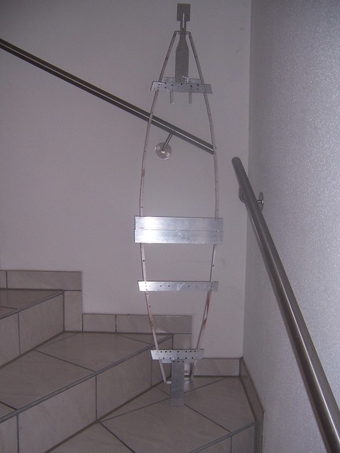
Next you see the deck in a much more advanced state and you can appreciate the challenge left, which is to remove as much as possible of the aluminium to achieve the lightest possible deck weight.
Blog this Post
- 12-23-2013, 09:16 PM
Hellmut1956
 Member
Join DateMay 2013Posts34
[h=2] [/h]
[/h]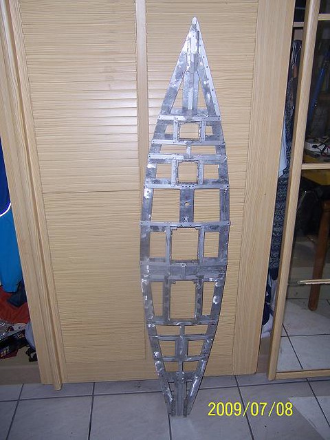
It highlights a challenge that is applicable to any long keel sailboat, it is the location of the center of gravity and is mentioned at quite a few places in this forum. I did choose aluminium to build the deck structure due to the strength of the metal and due to its low weight. Still so, after completion any material that can be removed will have to be removed.
But to achieve the goal to have this sailboat to be navigable at not only light winds, a lot of effort has to be put into ensuring that no space below the waterline has to be left empty if space is available lower within the hull.
Here you can see my son laminating the hull from within. The hull being made of wood, has the tendency, as wood works, to loose the plane surface achieved after many long sessions of sanding, after which you could not feel the individual wooden laths. The only way my experience tells me to make sure this does not happen is to laminate the hull symmetrically from within and from outside. This ensures the hull keeps the surfaces as plane as they are just after finishing the sanding of it. Sometimes I think I should have left the hull as it can bee seen, in the original colors of the wood. As we had to get the hull ready for my son to present it as its work at school, we colored it, keeping the structure of the wood visible, something I really regret. Now I will have to laminate the complete hull with mahogany veneer to achieve again a beautiful wooden color. if I ever build another wooden hull I will use wood premium wood. You can appreciate that by doing careful hull construction no filling material is required.
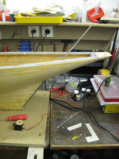
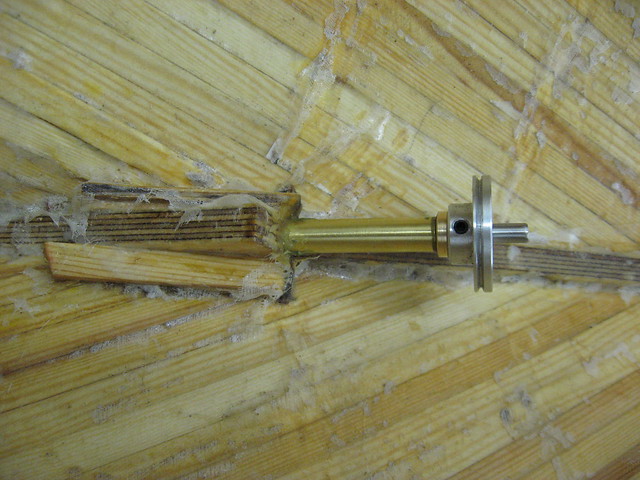
Here you can see how, with the help of a friend I prepared the rudder mounting. At the low end there is a brass tube in which the head of an allen screw fits. This way, screwing a screw from the bottom into the axis of the rudder, the rudder can be unmounted later, by just removing that screw. This construction much later proved to be too weak as the final displacement of the model of 29kg broke the wooden noose in which the axis of the rudder is fitted on the low side. I had to fix this by mounting a steel rod at the bottom of the keel, able to resist the stress on it of a 29kg model weight resisting on it!
Here you see the axis of the rudder within the hull. First i had the intention to have a servo pass the torque onto the axis of the rudder by the means of a cable and 2 drums. Now I have decided to replace the servo by a stepper motor and use a toothed cable instead. i have found a stepper motor, just 28x28 mm, with enough torque for the rudder function, but totally silent when being operated, opposed to the typical servo noise everybody knows. But more to those electronic elements in my model much later.

to close the thread for today, here a picture that gives an idea of how the model will look like. The hull shows the result of the not successful tries to get the hull properly colored, before deciding to go for laminating it with veneer.
 04-07-2015, 11:52 PM
#4
Junior Member
Thread Starter
Join Date: Apr 2015
Posts: 11
Likes: 0
Received 0 Likes
on
0 Posts
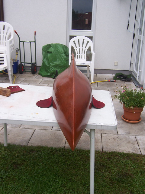
The target weight is 29 kg. here a foto of the front of the boat. As you can see, the color of the hull was not my tasate, but we had to do it for meeting the goals of my son for the school job! My son felt it looked like a dolphin!
The first foto shows the hull from below
the second from above with the preliminary made deck, mounted on top of the hull. Whats is missing of the structure of the deck is removing all aluminium to reduce its weight, to install a lightning of the deck, the 2 travellers I will install. Only then can i place the false deck on which I place the real deck planking.
Lets go on with the report about the model Carina. Next some pictures of the details how the labyrinth sealing of my deck around the removable constructions on deck.
As you might see you can see the U-profile, open to the top of the hull, the u-profile of the deck placed within the hulls u-profile has been opened to the inner side to allow water that passes the sealing of the specific construction to flow into the U-profile of the hull were it is being collected and can flow into a reservoir within the hull.
here you see how every opening in the deck is surrounded by a collar, the first barrier for water, on the top of the collar there will be glued a sealing strip onto which the removable deck construction is pressed, the second barrier to water and finally the labyrinth sealing shown in the previous picture. This way I am pretty sure no water will penetrate to the hull. This is specially important as the floatation leven of the hull will be pretty close to the deck level to ensure the deepest posible location for the center of gravity in the model.
Next a foto of the hull with the preliminary version of the removable deck mounted.

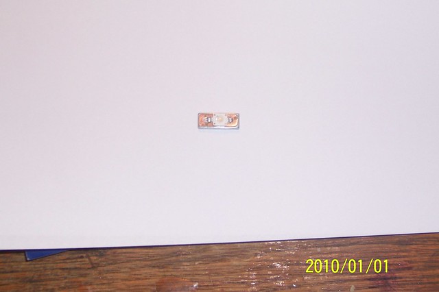
This was the first version of the small boards for the LEDs I plan to install into the deck to make a remote controllable dimming of the indirect lightning of the deck. Night is a great time to have the models on the lake and enjoy them with lightning. The lightning should on the lower intensity side just generate a small light on the floor of the deck and on the top side illuminate the deck as if it is in Monte Carlo and a party is going on! typical for me to jump onto ideas that come up as I advance with the construction of the model!
But this LED, a typical 20mA current LED, proved to deliver too little light, so I had to switch to high brightness LEDs that opposed to the max. 20 mA of the one on the foto can be sourced with up to 500 mA. This as a consequence opened the box of the pandorra! HB LEDs as those are called in short, generate a huge amount of heat that needs to be diffused. The consequence of this is, that not normal epoxy boards can be used but such with a core of aluminium that can take much more heat and diffuse it. But that brings other challenges! One is that you have to physically connect the aluminium core of the board of the HB LED to the aluminium structure of the deck to diffuse the heat from the LED to it, but not to have an electrically conducting connection. Means heat conducting but not electrical conducting. Well, after some research I found the adequate glue with this properties. Next was the challenge to ensure no electrical power conduct that feeds the LED would be short circuited while soldering. After some further research I found a supplier for repair coating used to fix the green coating that can be seen on commercial quality electronic circuit boards. Next is that with all this need described so far and resulting much more challenging with the use of HB LEDs I did want not more than just a small 5x5 mm square of the light source made to be visible and that it was a 100% sure that no water would penetrate the light source and cause a short circuit. Finally, as this LED making the light source was going to be build into my model I wanted to ensure that my dimming would be limited not to have the LED heated above a defined temperature. For this I found from a spin-off company from the ETH Zurich a temperature and humidity sensor in a just 3x3mm case self calibrating and providing the data digitally over a bus called I2C. This way, when I would be increasing the intensity of the light emitted by the HB LED, what means that more current would be flowing through it and as a consequence more heat would be generated within this HB LED, the temperature sensing of this electronic component would be delivering the actual temperature, measured from the aluminium core of the small board on which the HB LED was mounted and providing it to a microcontroller monitoring it and doing the dimming. As soon as a certain software defined temperature would be reached the software would consider this to be equivalent to 100% light emitting power. This way every single HB LED of the 20 plus that I would be installing on my model would limit the dimming to a temperature that assured that the HB LED suffered no damage due to overheating.
Here a picture of the lightning element build around the LED. Remember I have to be able to place every lightning element into every receptacle in the model and to be able to produce those, even after years with that precision. Until then I had be using my Bosch drill, which here proved not to be precise and repeatable enough to meet this goals. So I bought myself a drilling and milling machine.

With it I was able to build this setup that would ensure the repeatability of the lightning elements build using it.
The 4 brass strips with the screws in it represent the 2 ends of the lightning element shown in the drawing above, capable to conduct the electric power to the LED and a small printed circuit board to be soldered in between would have the HB LED on it and with the protective repair coating ensure that while soldering on short circuit to the aluminium core could happen.
Here you can see a try in making those small printed circuits boards with the aluminium core. This technology is not yet properly matured at the supplier and as a consequence, as I was unhappy with the results after a couple of tries, the provider was unable to do this boards himself. Fortunately I got enough usable of this circuits boards to satisfy my initial needs.
Those researches to find a usable and adequate way to address the innumerable challenges resulting from doing it "my way" require plenty of time, involve many failed tracks being pursued. Opposed as some might see it, I found this activity very satisfying and when I finally found a proper solution I was able to sell this knowhow as consulting services. The more expensive it is to replace a lightning element in an application, the more smart solutions that prevent failures or allow for preventive maintenance by being able to monitor the lightning element are justifiable. Remember, my main goal in this project is not to finish a model, but to keep my grey cells in the brain active while spending as little money as possible.
This image gives you the option to guess some of the challenges related to using a printed circuit card material that has an aluminium core opposed to the usual epoxy cores. Cutting the single board for single lightning element and soldering a HB LED on it using the reflow technique, made me aware of the challenges related. One is that cutting this small board out of the big one and having the copper surface to the edge of it, resulted in copper being connected to the core. as a result I had to sand the small board at its edges until the check with the Ohm-meter confirmed that no short circuit did exist any more. Also this picute illustrates that care has to be used to only apply very little soldering past to the pad so that after melting during the reflow process, no soldering material got in contact with the aluminium core. By magnifying the picture a ceramic coating can be seen, it is light green colored, that separates the copper from the aluminium core!
The first foto shows the hull from below
the second from above with the preliminary made deck, mounted on top of the hull. Whats is missing of the structure of the deck is removing all aluminium to reduce its weight, to install a lightning of the deck, the 2 travellers I will install. Only then can i place the false deck on which I place the real deck planking.
Lets go on with the report about the model Carina. Next some pictures of the details how the labyrinth sealing of my deck around the removable constructions on deck.
As you might see you can see the U-profile, open to the top of the hull, the u-profile of the deck placed within the hulls u-profile has been opened to the inner side to allow water that passes the sealing of the specific construction to flow into the U-profile of the hull were it is being collected and can flow into a reservoir within the hull.
here you see how every opening in the deck is surrounded by a collar, the first barrier for water, on the top of the collar there will be glued a sealing strip onto which the removable deck construction is pressed, the second barrier to water and finally the labyrinth sealing shown in the previous picture. This way I am pretty sure no water will penetrate to the hull. This is specially important as the floatation leven of the hull will be pretty close to the deck level to ensure the deepest posible location for the center of gravity in the model.
Next a foto of the hull with the preliminary version of the removable deck mounted.
This was the first version of the small boards for the LEDs I plan to install into the deck to make a remote controllable dimming of the indirect lightning of the deck. Night is a great time to have the models on the lake and enjoy them with lightning. The lightning should on the lower intensity side just generate a small light on the floor of the deck and on the top side illuminate the deck as if it is in Monte Carlo and a party is going on! typical for me to jump onto ideas that come up as I advance with the construction of the model!
But this LED, a typical 20mA current LED, proved to deliver too little light, so I had to switch to high brightness LEDs that opposed to the max. 20 mA of the one on the foto can be sourced with up to 500 mA. This as a consequence opened the box of the pandorra! HB LEDs as those are called in short, generate a huge amount of heat that needs to be diffused. The consequence of this is, that not normal epoxy boards can be used but such with a core of aluminium that can take much more heat and diffuse it. But that brings other challenges! One is that you have to physically connect the aluminium core of the board of the HB LED to the aluminium structure of the deck to diffuse the heat from the LED to it, but not to have an electrically conducting connection. Means heat conducting but not electrical conducting. Well, after some research I found the adequate glue with this properties. Next was the challenge to ensure no electrical power conduct that feeds the LED would be short circuited while soldering. After some further research I found a supplier for repair coating used to fix the green coating that can be seen on commercial quality electronic circuit boards. Next is that with all this need described so far and resulting much more challenging with the use of HB LEDs I did want not more than just a small 5x5 mm square of the light source made to be visible and that it was a 100% sure that no water would penetrate the light source and cause a short circuit. Finally, as this LED making the light source was going to be build into my model I wanted to ensure that my dimming would be limited not to have the LED heated above a defined temperature. For this I found from a spin-off company from the ETH Zurich a temperature and humidity sensor in a just 3x3mm case self calibrating and providing the data digitally over a bus called I2C. This way, when I would be increasing the intensity of the light emitted by the HB LED, what means that more current would be flowing through it and as a consequence more heat would be generated within this HB LED, the temperature sensing of this electronic component would be delivering the actual temperature, measured from the aluminium core of the small board on which the HB LED was mounted and providing it to a microcontroller monitoring it and doing the dimming. As soon as a certain software defined temperature would be reached the software would consider this to be equivalent to 100% light emitting power. This way every single HB LED of the 20 plus that I would be installing on my model would limit the dimming to a temperature that assured that the HB LED suffered no damage due to overheating.
Here a picture of the lightning element build around the LED. Remember I have to be able to place every lightning element into every receptacle in the model and to be able to produce those, even after years with that precision. Until then I had be using my Bosch drill, which here proved not to be precise and repeatable enough to meet this goals. So I bought myself a drilling and milling machine.
With it I was able to build this setup that would ensure the repeatability of the lightning elements build using it.
The 4 brass strips with the screws in it represent the 2 ends of the lightning element shown in the drawing above, capable to conduct the electric power to the LED and a small printed circuit board to be soldered in between would have the HB LED on it and with the protective repair coating ensure that while soldering on short circuit to the aluminium core could happen.
Here you can see a try in making those small printed circuits boards with the aluminium core. This technology is not yet properly matured at the supplier and as a consequence, as I was unhappy with the results after a couple of tries, the provider was unable to do this boards himself. Fortunately I got enough usable of this circuits boards to satisfy my initial needs.
Those researches to find a usable and adequate way to address the innumerable challenges resulting from doing it "my way" require plenty of time, involve many failed tracks being pursued. Opposed as some might see it, I found this activity very satisfying and when I finally found a proper solution I was able to sell this knowhow as consulting services. The more expensive it is to replace a lightning element in an application, the more smart solutions that prevent failures or allow for preventive maintenance by being able to monitor the lightning element are justifiable. Remember, my main goal in this project is not to finish a model, but to keep my grey cells in the brain active while spending as little money as possible.
This image gives you the option to guess some of the challenges related to using a printed circuit card material that has an aluminium core opposed to the usual epoxy cores. Cutting the single board for single lightning element and soldering a HB LED on it using the reflow technique, made me aware of the challenges related. One is that cutting this small board out of the big one and having the copper surface to the edge of it, resulted in copper being connected to the core. as a result I had to sand the small board at its edges until the check with the Ohm-meter confirmed that no short circuit did exist any more. Also this picute illustrates that care has to be used to only apply very little soldering past to the pad so that after melting during the reflow process, no soldering material got in contact with the aluminium core. By magnifying the picture a ceramic coating can be seen, it is light green colored, that separates the copper from the aluminium core!
04-07-2015, 11:56 PM
#5
Junior Member
Thread Starter
Join Date: Apr 2015
Posts: 11
Likes: 0
Received 0 Likes
on
0 Posts
Dear friends, I have continued having health problems, last on April 28th 2014. Something abbreviated "TIA", which is kind of a temporary stroke, pretty light, but having had a thrombosis in October and taking a brand new medicamentation called Xarelto, me and the doctors at the stroke unit were surprised this could happen being under this medicamentation! Well, being "special" in the way I work on my modell y probably have also to be "special" in health issues! Search for the cause of this is going on! One important part of my daily pray is to ask for enough years to pursue all those fascinating projects related to my sail ship. Lets go on!
There is an interdependence between between the status of my workshop and the tasks popping up in the process of building my sail boat! The need for certain equipment and tools to demand to adapt my workshop. During the last more than 12 months my focus has been on the workshop, but since the work on my model presented so far in the report a lot has been done and a lot more is being embraced!
Lets present the work on the workshop that relates closely to the projects on the model.
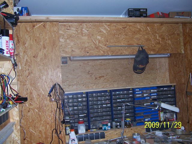
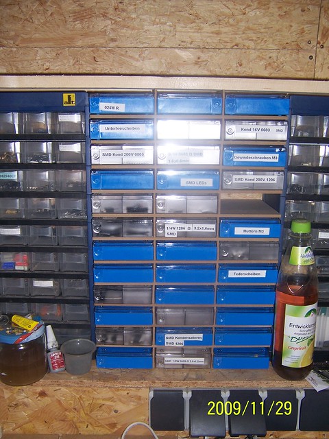
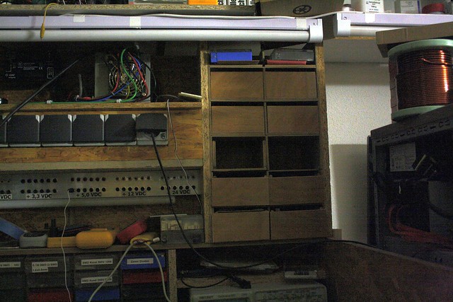
Here you can see the upper half of what I now call my old workbench. On top is an empty 60 cm depp space over the complete length of the workbench, used to store long stuff. I believe you never have enough space.below it, to the left and not visible to the right are 3 cabinets to store stuff. below the center is the neon light, the switch for the light, the empty space that will be used for a total of 144 assortment boxes in which I will be able to store the many small parts in an ordered fashion. Below 3 cabinets and more shelves for more even more assortment boxes. below more contact boxes. I believe there can never be enough!
Next the upper right side, were on the hidden wall of the right cabinet I have made provisions to store safely my welding and equipment.As you can see I have left no spare room without use. below you can see the the drawers. In an update made during the last 12 months I have shorten the drawers to be just 60 cm deep, as at the size of them at the status of this foto, was so big, that the stuff inside was a source of chaos in its own right.
Here a detailed photo of the shelves in the center part shown earlier.
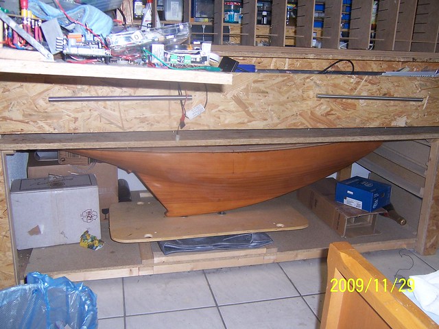
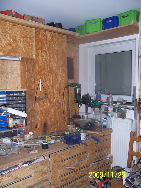
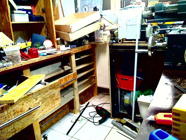
Here a photo of the center and left lower half of the old workbench. It shows the reason for the original start of building this workbench. My kids moved a scratching post for our cat and it crashed with the hull, leaving holes in it. So I decided to build an hangar for the hull and as a result came this workbench into existence.
In an empty spot left an the wall to the left of the old workbench and the entrance door I build my first version of an electronic lab, as the extent of the work related to electronics was proving to be huge. A side effect of this was, that I realized that of the past 2 decades I had purchased and accumulated so much electronic stuff, that it proved easier to buy something again, than trying to find what I had. In the center of the electronics workbench you can see a power supply for PCs modified to supply different tensions available in it and a a black box mounted next to it on the wall, a tension doubler that generated a 24 VDC 10 A, a value that could be added to the repertoire. Below it my unpreventable power sockets and below it another neon light. On the workdesk the sickness of my lab, I am just now finally getting this organized, huge amounts of anorganized parts!
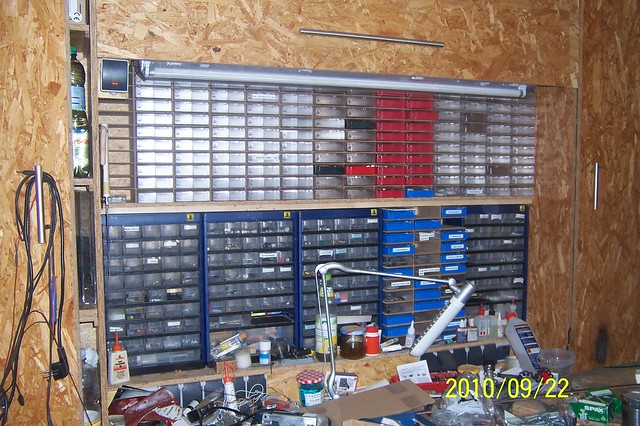
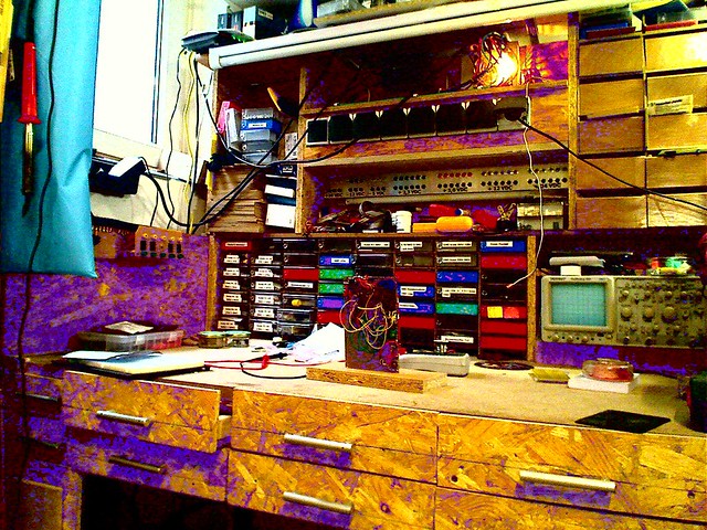
Here you can finally see the 144 assortment boxes! But as it was evident on the desk surface of the electronic workbench, it is equally evident of the desk surface of my old workbench. And I have to admit, that there is a second large room in the cellar filled with more stuff!
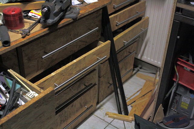
This old workbench here did good services over about 1 decade. As the structure of it, with one exception was build using wooden beams, some of the wooden beams started to give up, rendering some of the drawers useless as it became hard to open or close them. So I decided to update this old workbench by adding steel beams to hold the wooden boards on which the drawers slide.
This technique had proven itself during the construction of other elements of my workshop, I will describe them later, but you can see my "new" workbench on the right side of this photo!
The result of embracing this project was that the usual chaos exploded getting impossible to work on any other project. Added to this my health problems that started with a stroke in April 2012, continued with my heart stopping beat, getting a pacemaker inserted, i am now myself y "cyborg" , problems with wrong medicamentation and a thrombosis during 2013 and finally a second light stroke in April 2014 led to me starting to get depressed by not being able to experience success stories as part of my work on the model and the workshop.
On the floor in front of the old workbench you can see a steel beam of the kind used to support the boards that can be seen in the old workbench and on which the drawers slide.
But having fixed this new work pops up. First I need to decide how to subdivide the drawers and what to store where.

The large drawer that extents over the full width of the "hangar", about 180 cm and far to deep was a sink for stuff and a place where I could never again find anything in it. You can see 2 of the 3 grips equally spaced across the drawer, the hull in the hangar is 165 cm long, just to give you a feeling for its size. I have cut it in 3 equal width pieces, each with its own grip and a depth of just 60 cm. I have still not completed this, because I am missing some wooden parts I need and because simply I am bored working on the old workbench, so it waits for me to finish it.
04-07-2015, 11:57 PM
#6
Junior Member
Thread Starter
Join Date: Apr 2015
Posts: 11
Likes: 0
Received 0 Likes
on
0 Posts
After my first stroke a good friend decided to help me to get order into my workshop, while I was still recovering from the stroke. He really impressed me about with what creativity and a natural sense for organizing things and how heavy and intensive he worked , while I mostly was sitting next to him and giving instructions!
One of the key changes he introduced was, to separate those dirty work activities from those generating less dirt into the 2 separate areas of my workshop. A consequence of this approach was, that we decided to build a second workbench, now called the new one, while the other one became the attribute of being the old one. For this we removed the bed coach from that room part with the old workbench and placed it in front of the large cabinet in the other half. One of the side effects was that I got in trouble with my wife, as access to this cabinet got very difficult!
The space that got available in the first half by removing the bed coach was going to be the place for the new workbench. This new workbench would get the form of an "L".
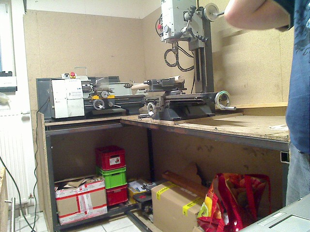
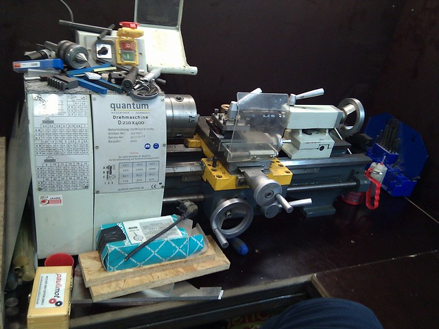
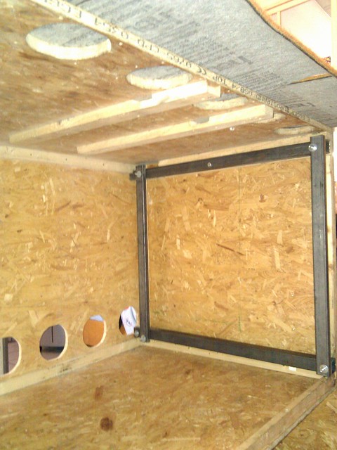
This new workbench should become the home for the milling machine and the lathe. In the picture you can see that the whole workbench is placed on top of compressed wooden boards, to protect the floor of the cellar and made using 40x40 mm steel beams, screwed together to allow for removal, should we change for a smaller residence in the future. Our current rented house has, including the cellar 4 floors and the day will come when neither me nor my wife can continue exercising going up and down those stairs!
So far only below the lathe and that part of the workbench desk surface has the strong plywood boards covered with a surface resistant to chemicals and very strong against mechanical stress. The whole backside wall of the workbench as of the moment of the photo was made using compressed wooden boards. A lot of thinking was spend to decide exactly where to place the 2 machines. A round wooden beam, 1 meter long, was fixed in the vice. This way i could assure myself that there was no space limitation to be expected when working on the milling machine. At the same time the lathe waa placed in such a way, that a piece to be worked upon in the milling machine could extent up to the back wall of the workbench behind the lathe. To the other side there was room up to the wall next to the entrance door.
For the lathe the same thinking took place. On one side operating the lathe forced the machine to be in a position were the operator, me, felt comfortable working on the machine. This forced to place the lathe as far to the left as possible. This also has the consequence that a part being machined on the lathe could extent to the back wall behind the milling machine side of the workbench. The pace below the desk surface is being used to store stuff in boxes which over time will be placed in their proper places. Huge steps forward have been done until today, but a lot of work is still being left.
In this 2 photos you can see how the desk surface and the back walls of the new workbench look like. The plywood boards used for this purpose are normally used to build cases to be filled with concrete in constructions. as a result of this function, this plywood boards have extremely strong surface. My objective is to have the surfaces of the desk of the new workbench always empty after working on the machines and the surfaces have to be easy to clean. I am not yet there to achieve my goal of an empty workdesk on my new workbench, but on my way there. I am in the process of building the infrastructure to make to rows of drawers below the surface of the desk of the new workbench. I will introduce you to this now, when I describe the uplift of the second half of my workshop, the cleaner room.
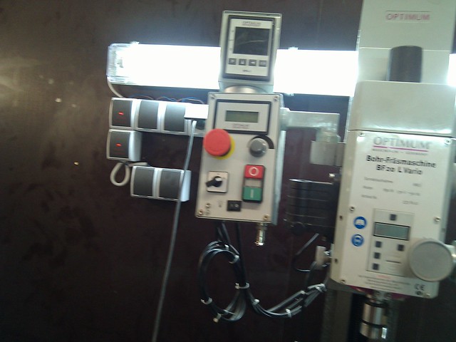

This series of pictures show you how I have completed the new workbench desk and back walls. but it also shows the ilumination and the electrical infrastructure of the new workbench. The 2 switches next to the lathe, the lower one disconnects electrically the whole workbench, the upper one the light and the power supply to the sockets and in consequence the power supply to the lathe.
The electrical wiring goes behind the back walls to the switches, the lightning and sockets next to the milling machine. The lower socket control the power supply to the 2 sockets next to it and as a consequence switch the milling machine ON and OFF by controlling the power supply to the sockets feeding them. The upper switch controls the light and the sockets next to it.
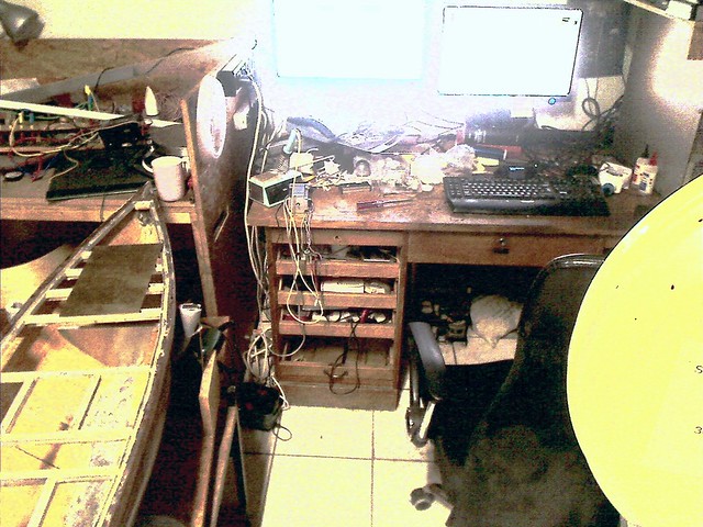
Here you can see my office desk and a bit to the right a second unit that will become my electronics workbench! On the front right you see a part of my band saw. This band saw was originally manufactured in the former communist part of Germany. It is simple but nearly impossible to destroy. This machine has proven its value countless times during my work on the workshop. I inherited it from somebody who had it in the stored away in a corner because he could not fix it. This very good friend who has helped me to do a lot of the work in the workshop spend a couple of hours on fixing it and now it is in perfect shape! I have my PC on it with 2 LCD screens, wonderful working tool, but cluttering my already chaotic office desk.
Now to the building of my new electronic workbench, which originally had served as a server cabinet and as the place for the printer and its consumables.
This picture shows how I am fixing carpet to what is going to be the bottom side of the electronic workbench. Again here, so it does not damage the floor. You can also see the round wholes in front of which I had fans installed which expelled the warm air coming from the servers in this cabinet.
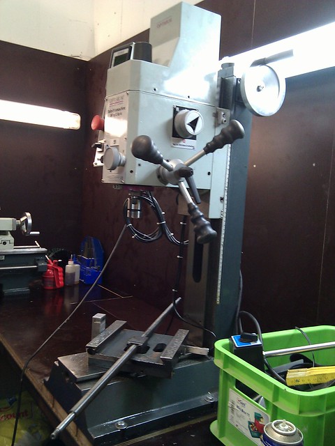
As I have written earlier, a technical problem with my milling machine, a screw used to fix the position of the coordinate table broke and i had to remove it. The result was that I decided to extent the work to do maintenance work and to recalibrate the whole machine. The other big cause for a mayor rework on my whole workshop was that I had to get the thousand of parts I got, accumulated over nearly 2 decades had to be placed and put in such an order that I could get access to them easier and not have to go to buy something I owned again. Finally, and this gets the loop of this thread back to the initial focus, the future work an my sailboat model, I new that now I was going to start to embrace the electronics projects for my sailboat. So I decided to move from having a small electronics workbench to make the real thing:
Here you see how I build a solid steel infrastructure into the workbench. This on one side is due to the fact that I will have to step on the desk surface to access stuff that I have on the shelves above and behind the furniture and I am pretty heavy, and also because I will ground this so that I can make a well grounded working environment

This picture shows my electronics workbench frame. As you can appreciate, it offers plenty of space to be used to setup a good working environment. The opening below the desk surface on the right has the purpose to give access to where the phone and Internet access points for our house are.

One thing an electronics workbench needs, besides good electrical grounding is a rich and powerful electrical power source. What I mean by rich is a large selection of different DC power sources. I do gain them from a modified PC power supply and by doubling the +12 VDC to get 24 VDC / 10A additionally. This on the other side requires robust and safe cabling. So what I did was to cannibalize my old and small electronic workbench. This foto shows a view from the rear of the "module". The foto shows the module upside down. At the top you can see the Aluminium "u" profile I have used to place the jacks for banana plugs. I have used solid copper cables to ensure that those would not even get heated, if a short circuit made a huge amount of current flow through them.
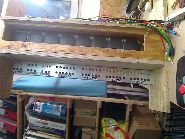
In this foto you see the same module viewed from the front side. The bottom row of jacks are all connected to ground, the top row has 6 jacks for each of the positive voltages, for the negative voltages only 2 jacks each and the 3 jacks for the second +24 VDC set will later, when I can afford to buy a 48 VDc power supply will make that voltage available as well. This 48 VDc are required for 2 purposes. One is that as I plan to realize a winch for the sheet to control the sail using a stepper motor. In my model I will have 12 LiFePO4 battery cells connected in series, which results in a maximum voltage of approx. 40 VDC feeding the stepper motor when the batteries are fully charged. So having 48 VDC available in my lab will allow me to do experiments that cover the full range of possible power voltage to the stepper motor from 24 VDC when the cells are empty up to the 48 VDC which is above the maximum 40 VDC my stepper motor will meet in the model. The other use of the planned 48 VDC power supply and this is why it will have 3kW power, is that I will feed a high end battery charger, called Pulsar 3. I have added the link to the vendor in english so you can have a look to it.
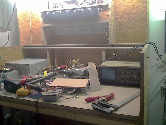
In this foto you can see where in the workbench the power supply module will be integrated. Also you can see something I keep as a rule on all my work. You can never have to many power plugs. On the right side on top of the desk surface you can see where I do integrate an oscilloscope. On the left side I have placed an outdated oscilloscope as a place holder for the future 48 VDC power supply.
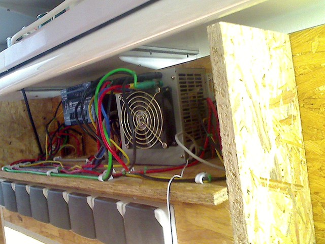
On this foto you can see the modified 600 W PC power supply and the strictly organized cabling. This is very important as otherwise it can be dangerous if some electric current conducting part is touched accidentally and / or it can be source to have a fire in the workshop initiated!
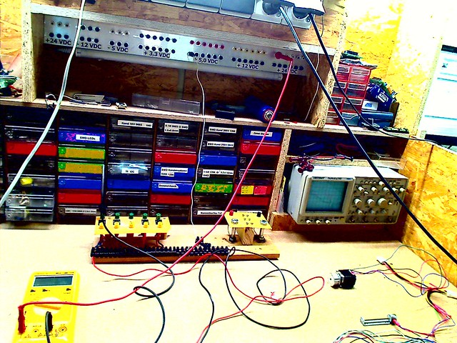
This foto shows the electronic workbench, not yet completed, but used for some initial experiments with stepper motors.
The following video, and I do ask your pardon for being such a bad speaker has been taken out of a short tutorial I have made on step motor control. The control board I use, called "stepRocker, is the one which will in my model to control the step motor to implement the winch functionality. In this video I was demonstrating how fast a stepper motor con rotate, even feeding it with what will be the smallest tension, approx. 24 VDC. I have setup the parameters to make the highest possible speed achievable and modified the so called "velocity" parameter which can have a value between 0 and 2047. I myself was surprised how fast I was able to get it rotating, before it blocked. This is why the video is relatively long. If you watch the blue tape fixed to the drive shaft you can see how fast it gets! One of the objectives why I developed my own concept for a sheet control in my sailboat was, that I want to implement the sheet control for the sail boat model in a way equivalent to that used on the original J-Class sailboats. But doing so requires to be able to change the length of the sheet by a total of 8400 mm or 330,71 inches. No imagine this drum, still being made with a length of the circumference of 400 mm. As a result just 21 full 360� turns results in a change of the length of the sheet of the desired 8400 mm!
Imagine the drum rotating at the speed that can be achieved and seen in this video, then you can judge, that those 21 turns can easily be achieved in 1 second. Watch the DMMs displaying the tension and the current as the stepping speed of the stepper increases.Please wait a bit for your browser displaying the youtube window!
As you can well imagine the high rotational speed shown in the video takes place with no "load" on the shaft of the motor, but it also takes place at just 25 VDC of tensi�n. To understand and communicate the technical details I will add this information later. The purpose is to demonstrate to you, why the electronic workbench is so important in my project of building my sail boat model.
One of the key changes he introduced was, to separate those dirty work activities from those generating less dirt into the 2 separate areas of my workshop. A consequence of this approach was, that we decided to build a second workbench, now called the new one, while the other one became the attribute of being the old one. For this we removed the bed coach from that room part with the old workbench and placed it in front of the large cabinet in the other half. One of the side effects was that I got in trouble with my wife, as access to this cabinet got very difficult!
The space that got available in the first half by removing the bed coach was going to be the place for the new workbench. This new workbench would get the form of an "L".
This new workbench should become the home for the milling machine and the lathe. In the picture you can see that the whole workbench is placed on top of compressed wooden boards, to protect the floor of the cellar and made using 40x40 mm steel beams, screwed together to allow for removal, should we change for a smaller residence in the future. Our current rented house has, including the cellar 4 floors and the day will come when neither me nor my wife can continue exercising going up and down those stairs!
So far only below the lathe and that part of the workbench desk surface has the strong plywood boards covered with a surface resistant to chemicals and very strong against mechanical stress. The whole backside wall of the workbench as of the moment of the photo was made using compressed wooden boards. A lot of thinking was spend to decide exactly where to place the 2 machines. A round wooden beam, 1 meter long, was fixed in the vice. This way i could assure myself that there was no space limitation to be expected when working on the milling machine. At the same time the lathe waa placed in such a way, that a piece to be worked upon in the milling machine could extent up to the back wall of the workbench behind the lathe. To the other side there was room up to the wall next to the entrance door.
For the lathe the same thinking took place. On one side operating the lathe forced the machine to be in a position were the operator, me, felt comfortable working on the machine. This forced to place the lathe as far to the left as possible. This also has the consequence that a part being machined on the lathe could extent to the back wall behind the milling machine side of the workbench. The pace below the desk surface is being used to store stuff in boxes which over time will be placed in their proper places. Huge steps forward have been done until today, but a lot of work is still being left.
In this 2 photos you can see how the desk surface and the back walls of the new workbench look like. The plywood boards used for this purpose are normally used to build cases to be filled with concrete in constructions. as a result of this function, this plywood boards have extremely strong surface. My objective is to have the surfaces of the desk of the new workbench always empty after working on the machines and the surfaces have to be easy to clean. I am not yet there to achieve my goal of an empty workdesk on my new workbench, but on my way there. I am in the process of building the infrastructure to make to rows of drawers below the surface of the desk of the new workbench. I will introduce you to this now, when I describe the uplift of the second half of my workshop, the cleaner room.
This series of pictures show you how I have completed the new workbench desk and back walls. but it also shows the ilumination and the electrical infrastructure of the new workbench. The 2 switches next to the lathe, the lower one disconnects electrically the whole workbench, the upper one the light and the power supply to the sockets and in consequence the power supply to the lathe.
The electrical wiring goes behind the back walls to the switches, the lightning and sockets next to the milling machine. The lower socket control the power supply to the 2 sockets next to it and as a consequence switch the milling machine ON and OFF by controlling the power supply to the sockets feeding them. The upper switch controls the light and the sockets next to it.
Here you can see my office desk and a bit to the right a second unit that will become my electronics workbench! On the front right you see a part of my band saw. This band saw was originally manufactured in the former communist part of Germany. It is simple but nearly impossible to destroy. This machine has proven its value countless times during my work on the workshop. I inherited it from somebody who had it in the stored away in a corner because he could not fix it. This very good friend who has helped me to do a lot of the work in the workshop spend a couple of hours on fixing it and now it is in perfect shape! I have my PC on it with 2 LCD screens, wonderful working tool, but cluttering my already chaotic office desk.
Now to the building of my new electronic workbench, which originally had served as a server cabinet and as the place for the printer and its consumables.
This picture shows how I am fixing carpet to what is going to be the bottom side of the electronic workbench. Again here, so it does not damage the floor. You can also see the round wholes in front of which I had fans installed which expelled the warm air coming from the servers in this cabinet.
As I have written earlier, a technical problem with my milling machine, a screw used to fix the position of the coordinate table broke and i had to remove it. The result was that I decided to extent the work to do maintenance work and to recalibrate the whole machine. The other big cause for a mayor rework on my whole workshop was that I had to get the thousand of parts I got, accumulated over nearly 2 decades had to be placed and put in such an order that I could get access to them easier and not have to go to buy something I owned again. Finally, and this gets the loop of this thread back to the initial focus, the future work an my sailboat model, I new that now I was going to start to embrace the electronics projects for my sailboat. So I decided to move from having a small electronics workbench to make the real thing:
Here you see how I build a solid steel infrastructure into the workbench. This on one side is due to the fact that I will have to step on the desk surface to access stuff that I have on the shelves above and behind the furniture and I am pretty heavy, and also because I will ground this so that I can make a well grounded working environment
This picture shows my electronics workbench frame. As you can appreciate, it offers plenty of space to be used to setup a good working environment. The opening below the desk surface on the right has the purpose to give access to where the phone and Internet access points for our house are.
One thing an electronics workbench needs, besides good electrical grounding is a rich and powerful electrical power source. What I mean by rich is a large selection of different DC power sources. I do gain them from a modified PC power supply and by doubling the +12 VDC to get 24 VDC / 10A additionally. This on the other side requires robust and safe cabling. So what I did was to cannibalize my old and small electronic workbench. This foto shows a view from the rear of the "module". The foto shows the module upside down. At the top you can see the Aluminium "u" profile I have used to place the jacks for banana plugs. I have used solid copper cables to ensure that those would not even get heated, if a short circuit made a huge amount of current flow through them.
In this foto you see the same module viewed from the front side. The bottom row of jacks are all connected to ground, the top row has 6 jacks for each of the positive voltages, for the negative voltages only 2 jacks each and the 3 jacks for the second +24 VDC set will later, when I can afford to buy a 48 VDc power supply will make that voltage available as well. This 48 VDc are required for 2 purposes. One is that as I plan to realize a winch for the sheet to control the sail using a stepper motor. In my model I will have 12 LiFePO4 battery cells connected in series, which results in a maximum voltage of approx. 40 VDC feeding the stepper motor when the batteries are fully charged. So having 48 VDC available in my lab will allow me to do experiments that cover the full range of possible power voltage to the stepper motor from 24 VDC when the cells are empty up to the 48 VDC which is above the maximum 40 VDC my stepper motor will meet in the model. The other use of the planned 48 VDC power supply and this is why it will have 3kW power, is that I will feed a high end battery charger, called Pulsar 3. I have added the link to the vendor in english so you can have a look to it.
In this foto you can see where in the workbench the power supply module will be integrated. Also you can see something I keep as a rule on all my work. You can never have to many power plugs. On the right side on top of the desk surface you can see where I do integrate an oscilloscope. On the left side I have placed an outdated oscilloscope as a place holder for the future 48 VDC power supply.
On this foto you can see the modified 600 W PC power supply and the strictly organized cabling. This is very important as otherwise it can be dangerous if some electric current conducting part is touched accidentally and / or it can be source to have a fire in the workshop initiated!
This foto shows the electronic workbench, not yet completed, but used for some initial experiments with stepper motors.
The following video, and I do ask your pardon for being such a bad speaker has been taken out of a short tutorial I have made on step motor control. The control board I use, called "stepRocker, is the one which will in my model to control the step motor to implement the winch functionality. In this video I was demonstrating how fast a stepper motor con rotate, even feeding it with what will be the smallest tension, approx. 24 VDC. I have setup the parameters to make the highest possible speed achievable and modified the so called "velocity" parameter which can have a value between 0 and 2047. I myself was surprised how fast I was able to get it rotating, before it blocked. This is why the video is relatively long. If you watch the blue tape fixed to the drive shaft you can see how fast it gets! One of the objectives why I developed my own concept for a sheet control in my sailboat was, that I want to implement the sheet control for the sail boat model in a way equivalent to that used on the original J-Class sailboats. But doing so requires to be able to change the length of the sheet by a total of 8400 mm or 330,71 inches. No imagine this drum, still being made with a length of the circumference of 400 mm. As a result just 21 full 360� turns results in a change of the length of the sheet of the desired 8400 mm!
Imagine the drum rotating at the speed that can be achieved and seen in this video, then you can judge, that those 21 turns can easily be achieved in 1 second. Watch the DMMs displaying the tension and the current as the stepping speed of the stepper increases.Please wait a bit for your browser displaying the youtube window!
As you can well imagine the high rotational speed shown in the video takes place with no "load" on the shaft of the motor, but it also takes place at just 25 VDC of tensi�n. To understand and communicate the technical details I will add this information later. The purpose is to demonstrate to you, why the electronic workbench is so important in my project of building my sail boat model.
04-07-2015, 11:59 PM
#7
Junior Member
Thread Starter
Join Date: Apr 2015
Posts: 11
Likes: 0
Received 0 Likes
on
0 Posts
Now having accumulated electronics components over about 1.5 decades and being ashamed of not having found stuff that a good friend of mine borrowed me, it became evident that a much larger effort had to be made to organize and store all those components to have the chance to find them. the first step was to build shelves for drawers in which I could store all those items so that I would stop searching forever whenever I needed something.
Here you can see how I am building drawers using the empty space on the backwall of my workbench, next to the power supply module.

Here you can see how I build the infrastructure for 2 rows of drawers below the desk surface, but still high enough so my legs fit below! You can see also on the desk surface how the infinite number of stuff looking to be stored at a meaningful place cluttered the surface!
Here you can not only see the 8 drawers now available, the grips build by myself, but you can also see the huge number of sortiment boxes integrated into the rear wall of my electronics workbench. But you can also see, how the light bulb used to apply the minimum load required to operate the PC power supply, shining indicated that the power supply is switched ON!
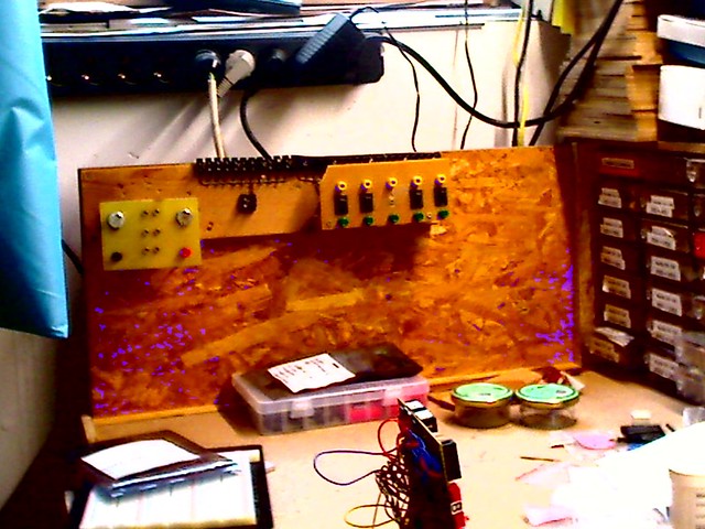
Here you can see how I have mounted a special unit to the left wall of my workbench. This unit plays a very important role. On the right side of this unit you can see 2 rows of jackets, one green colored, the other one yellow. The idea is to support what is often needed. I can connect to each of the green jackets the positive pole of one of the many different DC power supplies my power supply modules offers, using a cable with banana plugs on each side. This way I can have up to 4 different power supply tensions available. Any cable with a banana plug on one side plugged into the corresponding yellow jacket can be switched ON or OFF, using the corresponding switch on the board on the left side of the unit. But not just that, connected to the same switch I have 6 connectors to which I can connect a cable by fixing it with a screw. You can see the black devices on the upper side of the board. cables connected here are also controlled by the switch. Due to a thread on a another forum I will add an LED to indicate additionally if the switch is set to ON or OFF! In the middle section of this unit you can see where i have to connect the Ground and the 12 connectors associated with it. Interrupting just the positive pole is enough to switch the power off from a connected circuit, as the circuit is the open! To the left side of the module is a unit I made specifically to connect a battery charger to the power supply. This chargers usually have connectors adequate to connect the charger to a lead battery as used in cars. With 2 M10 screws which can be connected to the power supply through the black and red jackets i can easily connect such chargers to the power supply!
Another objective of screwing the unit to the side wall of the bench was the intent to keep the surface of the desk as empty as I could, as having stuff on the desk surface proved to be the starting point of chaos! The same reason is behind the placement of the soldering iron as shown on the next picture:
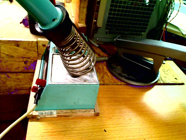
I have placed the phone on a turning table between my office desk and my electronic workbench, to have good access to the phone from both sides. I have increased the size of this surface in from of the PC to put the soldering iron there, but also to place a cabinet for 2 larger drawers below. Ther are plenty of things to large to place elsewhere but that need to be easily accessible.
A funny side effect of this massive expansion of shelves and drawers and sortiment boxes is that it becomes hard to find a specific item.
Just look on the number of boxes in the shelf of what I call my old workbench. Just in the shelves above the blue cabinets i have space for 144 sortiment boxes, each with up to the places inside. So just here can be 1440 different items stored! When ever I look for something I start to stand in front of the shelves reading the text labels to find what I am looking for. As the drawers in the old workbench are not yet fully organized and in consequence properly labeled, I always have to try to remember where I have placed a certain item. So even having invested more then 1 year updating my workshop and still being left with lot of sorting and storing and finishing work and labeling, I have been left with a much smaller but still nats problem. Where is something specific I am looking for and what are all the things I got in stock! So I have started recently learning to program a database using Access from the Microsoft Office software to help me where to find something. As due to my health problems with my heart rhythm and consequently the stopping of my heart for a pretty long time, my mental capabilities have suffered and I notice this when trying to program the database. But I will get it done! I have been investigating a bit what commercial solutions exist and have a pretty clear picture as to how to program it. I will divide my workshop in areas, such as old workbench, new workbench, electronic workbench and so on and will divide those areas into sectors and the drawers and shelf locations will be numbered by row and column numbers. So when i select a certain area a picture appears on the screen, when I select a sector that sector will appear highlighted on this foto. This way I know how to find the storage location. When selecting a specific device I will add a foto of it. You would not believe how many things I have I had forgotten and did just know about them during my efforts of putting order into this chaos.
I know that many consider me crazy, and may be I am. But my purpose of building this model sailboat is to use it to learn and apply the very many technologies that you encounter in our hobby of naval models. Known and familiar to everyone is the work with wood, with plastics like epoxy and so one. We all know about how to install servos and all the stuff that makes or models R/C controllable. Well, having worked for many years in the semiconductor and telecommunications industry, I have seen self build and developed electronics as an area were a lot of new grounds can be addressed and the dedication to this helps me to train my grey cells, something even more important know, were due to health problems I have a special need to exercise those cells so that damage done by too long period of time without oxygen supply can fix itself by reorganizing my brain. So, please be aware of, that the many years investigating, studying and experimenting with the electronics to achieve certain things in my sail boat have led to spend a lot of effort and time on topics, that while strongly related to our hobby, are fields you normally do not encounter in a step by step report on building a model. I like to say, that the way is my goal and not the finishing of the model.
Having written the above, i have been thinking about how to organize my reporting of my work towards implementing my own mechanism for sheet control. I will assume that the reader has little background on the topic and so the report will introduce you with many pictures and some videos on the different topics, on what is the objective and how I plan to address it. The whole project is work in progress!
My goal at the beginning, I did have close to zero knowledge about sail boats, was to engage in building a sailboat opposed to sail planes that I used to build and fly, because having lost my job I wanted to need to spend little money. So I purchased the plan for a long keel sailboat and build the hull as presented in the first �art of this report. Then I learned about the beauty of sail boats of the J-Class, the Endeavour being one of them. The result of getting to know this sail boats was, that I wanted to realize a model of the kind of thise sailboats. One characteristic of those sail boats is that they have huge sail areas, something that makes models build along the example of those boats very sensitive to stronger winds. This lead to have me introduce some goals and concepts into the way I build my model to achieve the best possible results. In the plan that I used to build my hull there were 2 versions, which were different by the height of the deck. I build mine with the higher deck. Another benefit of the design of my hull is, that it is wider than the hulls of the J-Class sailboats. Finally i decided to move the waterline close to the deck achieving a higher displacement and as a consequence my test in a water pool was, that my model could have 29 kg weight. This weight is approx. more than twice of the original value!
The next aspect to take into account to make the sail boat capable to navigate with stronger winds could be reducing the size of the sails. Well, I loved the picture of the J-Class also due to the impressive sails and compared to those the sail area of the sail in the plan for my hull. I kept it unchanged, resulting in a much smaller sail area than the one you find on the Endeavour i.e., but still larger than those of normal sail boat models.
Finally the location of the center of gravity is key. I set myself the goal to achieve the lowest possible location for the center of gravity by ensuring no empty space was left empty low in the hull. The only exception to this over all rule s the deck. I had decided early in the design process of the hull, that my deck would be fully detachable, but that no compromise would be done to ensure that no water could get into the hull!
Another important factor as to why I have chosen i.e. the large battery cells in my model was the goal to ensure the maximum possible capacity of the battery to be available on board. I could not find any source that reliably would enable me to estimate the power consumption of the two large stepper motors I have planned to build into my hull as winches, 3 Nm torque each. So I wanted to be sure that when the model would be ready it could navigate with a single charge of a battery long enough for what was needed for day on the pont. I knew, that the power consumption of stepper motors was highest, when not stepping, means supplying holding torque. As the stepper motors holding the sheet without moving would be the operation mode in which the stepper motors would spend most of the time, I had to assume worst case power consumption. As my learning curve on the subject improved I decided to use electrical brakes to ho�ld the stepper motor in position and as a consequence being able to power down the stepper motor. For your information. Electrical brakes of the kind used, are without power applied braking the shaft of a motor and therefore hol�ding it in its position. Applying 24 VDC the break releases. So the use of such electrical breaks would nearly eliminate the power consumption of the 2 stepper motors during most of its time. Still so,i decided to stick with my original goal to use batteries with the largest capacity possible.
The next thing that became evident to me was, that i was going to use batteries using a chemistry based on Lithium. I learned that there are different chemistries and the frequently used chemistries like Lipos and so on had a potential problem of catching fire. The reason why in many threads i read about this batteries it was suggested to remove them from the model for storage or charging and even to store those batteries in a fire safe container. Well, I realized pretty soon, that my batteries could not be removed easily and that as a consequence I would have to choose a chemistry with less capacity, but much more stable. I came to the conclusion to use LiFePO4 chemistry in my batteries and found a type with 16 Ah of capacity from Headway.
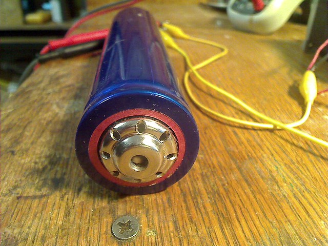
This battery with a diameter of 40 mm and a length of 173 mm with 16 AH was not much longer than the smaller version with just 10 Ah. Unloaded to the point were it has to be recharged the LiFePO4 cell supplies approx. 2.0 VDC, so to ensure the electrical breaks could be operated until the very end of the operating time I had to have 12 of this battery cells build into my hull. So this 2 reasons are responsible that I have 12 of this LiFePO4 batteries build into my model. I am aware that today, many years after I made the design decision, due to a much better understanding of the subject and due to dramatic development in the ICs to control stepper motors, were I have to specifically name those from the company Trinamic, energy consumption of stepper motors can be dramatically reduced with the result, that my model has an overly powerful battery pack installed, offering a capacitance much higher than required. But you all know, better too much, than to little! The weight and the space required to have those 12 cells build into my hull are not only not a problem, but effectively have a great contribution to achieve the 29 kg of weight and to ensure a low center of gravity.
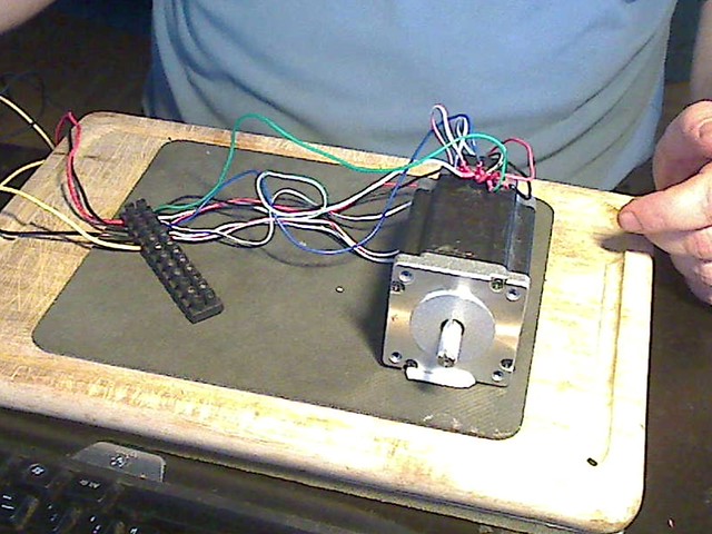
Here a picture of one of the 2 stepper motors to be used to implement the winch functionality in my sailboat. As you can see they are relatively big, the square geometry of the motor has a 63 mm length per side and about 90 mm length and a weight of approx. 1250g., totalling the contribution of both motors 2.5 kg. Each battery cell has a weight of 485 g * 12 = 5,820 kg. The sum of about 8,3kg for batteries and motors makes evident, that the proper placement of this elements in the hull would play a very important role in achieving the proper balance of weight in the hull. But, and this is typical to what I always encounter as I go into any of the many subjects related to my project, there is one more aspect to take into account.
Each battery cell has 3.6 * 16 A = 57,6 Wh of energy stored. Should i use the real batteries for the diverse works in the construction of the hull, the danger from accidental short circuits could be huge, as each cell can provide during short circuit 240 A of current + 3.6 V = 864 W of energy during up to 4 minutes. Don�t let us even think about something going wrong with all 12 cells at a time! The consequence of this is that I decided to build, what I call fake batteries:
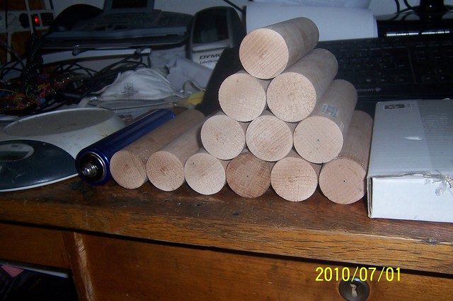
For doing this I purchased round wooden bars, 40 mm diameter and did cut pieces equivalent in length to those of the batteries. You see the on the picture. What i have not pointed out so far, is that this batteries have the very useful characteristic, to have M8 threaded holes at both ends allowing to connect the batteries via screws. So my fake batteries had to have the same threaded holes at their poles. The next aspect to fix was their weight of the fake batteries, it had to be identical to those of the original. To accomplish this I computed the amount of lead I would require to have those fake batteries to have the same weight as the original batteries and compute the volume of the amount of lead required. This defined the length, the depth and the width of the grooves, which filled with lead would help to achieve the objective. I could use the rotating device I had purchased to mill the drum I would need for the sheet.
Here you can see how I am building drawers using the empty space on the backwall of my workbench, next to the power supply module.
Here you can see how I build the infrastructure for 2 rows of drawers below the desk surface, but still high enough so my legs fit below! You can see also on the desk surface how the infinite number of stuff looking to be stored at a meaningful place cluttered the surface!
Here you can not only see the 8 drawers now available, the grips build by myself, but you can also see the huge number of sortiment boxes integrated into the rear wall of my electronics workbench. But you can also see, how the light bulb used to apply the minimum load required to operate the PC power supply, shining indicated that the power supply is switched ON!
Here you can see how I have mounted a special unit to the left wall of my workbench. This unit plays a very important role. On the right side of this unit you can see 2 rows of jackets, one green colored, the other one yellow. The idea is to support what is often needed. I can connect to each of the green jackets the positive pole of one of the many different DC power supplies my power supply modules offers, using a cable with banana plugs on each side. This way I can have up to 4 different power supply tensions available. Any cable with a banana plug on one side plugged into the corresponding yellow jacket can be switched ON or OFF, using the corresponding switch on the board on the left side of the unit. But not just that, connected to the same switch I have 6 connectors to which I can connect a cable by fixing it with a screw. You can see the black devices on the upper side of the board. cables connected here are also controlled by the switch. Due to a thread on a another forum I will add an LED to indicate additionally if the switch is set to ON or OFF! In the middle section of this unit you can see where i have to connect the Ground and the 12 connectors associated with it. Interrupting just the positive pole is enough to switch the power off from a connected circuit, as the circuit is the open! To the left side of the module is a unit I made specifically to connect a battery charger to the power supply. This chargers usually have connectors adequate to connect the charger to a lead battery as used in cars. With 2 M10 screws which can be connected to the power supply through the black and red jackets i can easily connect such chargers to the power supply!
Another objective of screwing the unit to the side wall of the bench was the intent to keep the surface of the desk as empty as I could, as having stuff on the desk surface proved to be the starting point of chaos! The same reason is behind the placement of the soldering iron as shown on the next picture:
I have placed the phone on a turning table between my office desk and my electronic workbench, to have good access to the phone from both sides. I have increased the size of this surface in from of the PC to put the soldering iron there, but also to place a cabinet for 2 larger drawers below. Ther are plenty of things to large to place elsewhere but that need to be easily accessible.
A funny side effect of this massive expansion of shelves and drawers and sortiment boxes is that it becomes hard to find a specific item.
Just look on the number of boxes in the shelf of what I call my old workbench. Just in the shelves above the blue cabinets i have space for 144 sortiment boxes, each with up to the places inside. So just here can be 1440 different items stored! When ever I look for something I start to stand in front of the shelves reading the text labels to find what I am looking for. As the drawers in the old workbench are not yet fully organized and in consequence properly labeled, I always have to try to remember where I have placed a certain item. So even having invested more then 1 year updating my workshop and still being left with lot of sorting and storing and finishing work and labeling, I have been left with a much smaller but still nats problem. Where is something specific I am looking for and what are all the things I got in stock! So I have started recently learning to program a database using Access from the Microsoft Office software to help me where to find something. As due to my health problems with my heart rhythm and consequently the stopping of my heart for a pretty long time, my mental capabilities have suffered and I notice this when trying to program the database. But I will get it done! I have been investigating a bit what commercial solutions exist and have a pretty clear picture as to how to program it. I will divide my workshop in areas, such as old workbench, new workbench, electronic workbench and so on and will divide those areas into sectors and the drawers and shelf locations will be numbered by row and column numbers. So when i select a certain area a picture appears on the screen, when I select a sector that sector will appear highlighted on this foto. This way I know how to find the storage location. When selecting a specific device I will add a foto of it. You would not believe how many things I have I had forgotten and did just know about them during my efforts of putting order into this chaos.
I know that many consider me crazy, and may be I am. But my purpose of building this model sailboat is to use it to learn and apply the very many technologies that you encounter in our hobby of naval models. Known and familiar to everyone is the work with wood, with plastics like epoxy and so one. We all know about how to install servos and all the stuff that makes or models R/C controllable. Well, having worked for many years in the semiconductor and telecommunications industry, I have seen self build and developed electronics as an area were a lot of new grounds can be addressed and the dedication to this helps me to train my grey cells, something even more important know, were due to health problems I have a special need to exercise those cells so that damage done by too long period of time without oxygen supply can fix itself by reorganizing my brain. So, please be aware of, that the many years investigating, studying and experimenting with the electronics to achieve certain things in my sail boat have led to spend a lot of effort and time on topics, that while strongly related to our hobby, are fields you normally do not encounter in a step by step report on building a model. I like to say, that the way is my goal and not the finishing of the model.
Having written the above, i have been thinking about how to organize my reporting of my work towards implementing my own mechanism for sheet control. I will assume that the reader has little background on the topic and so the report will introduce you with many pictures and some videos on the different topics, on what is the objective and how I plan to address it. The whole project is work in progress!
My goal at the beginning, I did have close to zero knowledge about sail boats, was to engage in building a sailboat opposed to sail planes that I used to build and fly, because having lost my job I wanted to need to spend little money. So I purchased the plan for a long keel sailboat and build the hull as presented in the first �art of this report. Then I learned about the beauty of sail boats of the J-Class, the Endeavour being one of them. The result of getting to know this sail boats was, that I wanted to realize a model of the kind of thise sailboats. One characteristic of those sail boats is that they have huge sail areas, something that makes models build along the example of those boats very sensitive to stronger winds. This lead to have me introduce some goals and concepts into the way I build my model to achieve the best possible results. In the plan that I used to build my hull there were 2 versions, which were different by the height of the deck. I build mine with the higher deck. Another benefit of the design of my hull is, that it is wider than the hulls of the J-Class sailboats. Finally i decided to move the waterline close to the deck achieving a higher displacement and as a consequence my test in a water pool was, that my model could have 29 kg weight. This weight is approx. more than twice of the original value!
The next aspect to take into account to make the sail boat capable to navigate with stronger winds could be reducing the size of the sails. Well, I loved the picture of the J-Class also due to the impressive sails and compared to those the sail area of the sail in the plan for my hull. I kept it unchanged, resulting in a much smaller sail area than the one you find on the Endeavour i.e., but still larger than those of normal sail boat models.
Finally the location of the center of gravity is key. I set myself the goal to achieve the lowest possible location for the center of gravity by ensuring no empty space was left empty low in the hull. The only exception to this over all rule s the deck. I had decided early in the design process of the hull, that my deck would be fully detachable, but that no compromise would be done to ensure that no water could get into the hull!
Another important factor as to why I have chosen i.e. the large battery cells in my model was the goal to ensure the maximum possible capacity of the battery to be available on board. I could not find any source that reliably would enable me to estimate the power consumption of the two large stepper motors I have planned to build into my hull as winches, 3 Nm torque each. So I wanted to be sure that when the model would be ready it could navigate with a single charge of a battery long enough for what was needed for day on the pont. I knew, that the power consumption of stepper motors was highest, when not stepping, means supplying holding torque. As the stepper motors holding the sheet without moving would be the operation mode in which the stepper motors would spend most of the time, I had to assume worst case power consumption. As my learning curve on the subject improved I decided to use electrical brakes to ho�ld the stepper motor in position and as a consequence being able to power down the stepper motor. For your information. Electrical brakes of the kind used, are without power applied braking the shaft of a motor and therefore hol�ding it in its position. Applying 24 VDC the break releases. So the use of such electrical breaks would nearly eliminate the power consumption of the 2 stepper motors during most of its time. Still so,i decided to stick with my original goal to use batteries with the largest capacity possible.
The next thing that became evident to me was, that i was going to use batteries using a chemistry based on Lithium. I learned that there are different chemistries and the frequently used chemistries like Lipos and so on had a potential problem of catching fire. The reason why in many threads i read about this batteries it was suggested to remove them from the model for storage or charging and even to store those batteries in a fire safe container. Well, I realized pretty soon, that my batteries could not be removed easily and that as a consequence I would have to choose a chemistry with less capacity, but much more stable. I came to the conclusion to use LiFePO4 chemistry in my batteries and found a type with 16 Ah of capacity from Headway.
This battery with a diameter of 40 mm and a length of 173 mm with 16 AH was not much longer than the smaller version with just 10 Ah. Unloaded to the point were it has to be recharged the LiFePO4 cell supplies approx. 2.0 VDC, so to ensure the electrical breaks could be operated until the very end of the operating time I had to have 12 of this battery cells build into my hull. So this 2 reasons are responsible that I have 12 of this LiFePO4 batteries build into my model. I am aware that today, many years after I made the design decision, due to a much better understanding of the subject and due to dramatic development in the ICs to control stepper motors, were I have to specifically name those from the company Trinamic, energy consumption of stepper motors can be dramatically reduced with the result, that my model has an overly powerful battery pack installed, offering a capacitance much higher than required. But you all know, better too much, than to little! The weight and the space required to have those 12 cells build into my hull are not only not a problem, but effectively have a great contribution to achieve the 29 kg of weight and to ensure a low center of gravity.
Here a picture of one of the 2 stepper motors to be used to implement the winch functionality in my sailboat. As you can see they are relatively big, the square geometry of the motor has a 63 mm length per side and about 90 mm length and a weight of approx. 1250g., totalling the contribution of both motors 2.5 kg. Each battery cell has a weight of 485 g * 12 = 5,820 kg. The sum of about 8,3kg for batteries and motors makes evident, that the proper placement of this elements in the hull would play a very important role in achieving the proper balance of weight in the hull. But, and this is typical to what I always encounter as I go into any of the many subjects related to my project, there is one more aspect to take into account.
Each battery cell has 3.6 * 16 A = 57,6 Wh of energy stored. Should i use the real batteries for the diverse works in the construction of the hull, the danger from accidental short circuits could be huge, as each cell can provide during short circuit 240 A of current + 3.6 V = 864 W of energy during up to 4 minutes. Don�t let us even think about something going wrong with all 12 cells at a time! The consequence of this is that I decided to build, what I call fake batteries:
For doing this I purchased round wooden bars, 40 mm diameter and did cut pieces equivalent in length to those of the batteries. You see the on the picture. What i have not pointed out so far, is that this batteries have the very useful characteristic, to have M8 threaded holes at both ends allowing to connect the batteries via screws. So my fake batteries had to have the same threaded holes at their poles. The next aspect to fix was their weight of the fake batteries, it had to be identical to those of the original. To accomplish this I computed the amount of lead I would require to have those fake batteries to have the same weight as the original batteries and compute the volume of the amount of lead required. This defined the length, the depth and the width of the grooves, which filled with lead would help to achieve the objective. I could use the rotating device I had purchased to mill the drum I would need for the sheet.
04-08-2015, 12:01 AM
#8
Junior Member
Thread Starter
Join Date: Apr 2015
Posts: 11
Likes: 0
Received 0 Likes
on
0 Posts
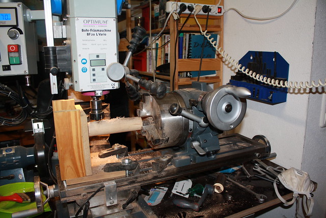
In this picture you could see my milling machine milling the longholes as computed, while the rotating device made it easy to mill the longholes every 120� for a total of 3!
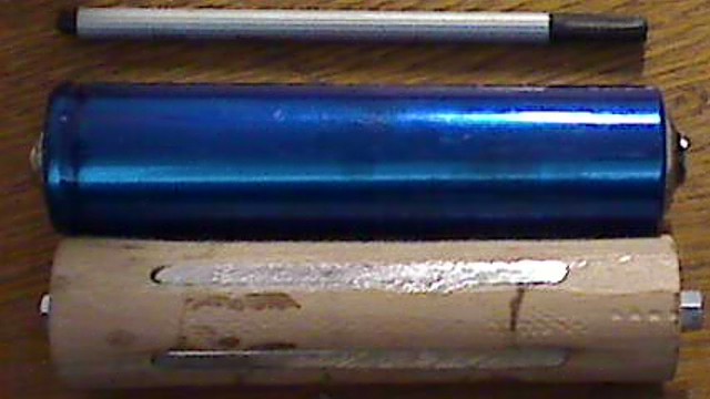
Finally here you see one of the 12 fake batteries made. After filling the longholes with melted lead with a file I did ensure the external geometry of the fake battery did not exceed the 40 mm diameter and removed lead until the weight of each fake battery was exakt 485 g as the original.
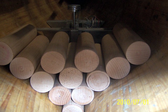
First I confess, I had planned to place all 12 batteries in a single bx and place the 2 stepper motors next to it on the bottom of the hull. The pictures shows how the 12 cells would have fitted and behind you can see that I had planned to have the rotation of the shaft of the stepper motor to be turned vertically using a gear. The reason was, that in those days I had still planned to implement the sheet control in the usual manner. i assume it is known, so I will not explain it.
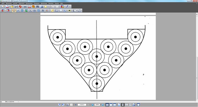
The graphic shown shows how I had envisioned the placement of the batteries. As this was distant from being the optimum to accomplish the lowest center of gravity possible and as a result of developing the concept of a new way to control the sheet for the control of the sails, I fully changed my concept.
This foto from the original Endeavour shows how the sheet to control the position of the main sale is connected. The sheet in total goes 6x from deck to the boom and back. This geometry in a first approximation to my model resulted in the need to displace the sheet and as a consequence change its available length by 8400 mm or 8.4 meters. This, I think it is called pulley in english, was needed on the original sail boat to make it possible to control the sail position by human beings. Even in communities that emphasize on building sail boats strictly the way they were originally, I had found that for actual sailing the model the pulley was replaced by a single sheet, so that the sheet displacement could be handled by the existing methods. Using a pulley system in the hull, i.e. to double the length of the sheet displacement would not make it possible to achieve the required sheet displacement without loosing too much of the torque made available by the winch!
Here comes my system into place. By replacing a standard winch with a limited number of revolutions of the drum on it by a stepper motor I was not longer limited to achieve any amount of sheet displacement desired. Watching the video presented earlier it gets evident, that the stepper motor planned would have no problem displacing the amount of sheet required and to do this in a short period of time, equivalent to that, what it would take the boom of the main sail to turn 180� during a jibe, the mode of turning of a sail boat were the maximum rotation speed happens!
To this has to be added another feature of a stepper motor. The faster it steps, the faster it rotates and the less torque it has available. This is the reason why in the video shown above there comes a moment when the motor stops moving. The reason for this is, that the rotating coils of the stepper motor create by induction a tension which is poled opposite to the applied voltage. To explain it in another way. Lets assume we operate the stepper motor applying a voltage of 40 VDC to it. The faster the stepper motor makes its steps the faster the applied tension value changes. The faster it changes, the stronger the induced voltage is. So there would be a certain speed at which the induced voltage is -20 VDC. Adding the applied voltage and the induced voltage results in a sum of just 20 VDC or 50% of the applied voltage. if we assume that the torque is proportional to the value of the applied voltage, the stepper motor will have 0nly 50% of its original torque. This is why stepper motors are not used where faster rotating speeds are required! So, as in the case of a jibe maneuver the stepper motor has to reduce the length of the sheet while the boom moves towards the center line of the hull in the short time it takes the boom to rotate to the centerline of the hull and has to extend again the sheet length. while the boom moves to the 90� position away from the center line. If the stepper motor is capable to adapt the length of the sheet exactly to the required length depending of the actual position of the boom, the sheet remains tensioned and cannot cause problems it would otherwise have. We also can appreciate that in the case of this extreme maneuver during the turn of the move the sheet would not load the stepper motor by pulling on the sheet, as the wind load has not to be countered. Only when the boom reaches its final position it will again have the wind pressure on its sail cause a pull on the sheet and this demand from the stepper motor to have the torque value required to hold the boom! Not being exposed to a load torque means that the stepper motor could step faster!
Now how do we get the control loop for this system to work? Well, on one side the electronics need to monitor the angle of the boom. By doing so the control circuitry and the software running on it would always know the current position of the boom and as a consequence the length of the sheet required. How can this be accomplished? Well, in the gooseneck fitting the axis around which the boom of the main sale rotates around the vertical axis. i do not know if in english there are this to terms. In german axis means a fixed shaft, the term Welle means the rotating shaft. So if in the gooseneck fitting I do implement such a rotating shaft that rotates accordingly to the rotation of the boom and I do mount a magnet on this rotating shaft in a way that it rotates directly above the deck surface generating a rotating magnetic field, then a magnetic angular sensor can monitor that actual boom angles as it rotates. The sensor would be mounted under the deck surface, a thin plastic foil covering the whole in the deck would make it possible without entering in contact with water and allowing the magnetic field to rotate freely with the magnet just 1-2 mm away from the sensor. This way the sensor envisioned would offer a 14 bits resolution of the angle of the boom in time intervals more than short enough. as the boom only turns 90� to either side from the centerline of the hull, the 14 bits, equal 16 x 1024 possible positions over 360�, would only knew 1/4 or 12 bits or 4096 possible boom positions from the center line to the orthogonal position of 90�. That is a lot, much, much more, than what even the best operator on a radio control Transmitter could take benefit of. This excessive position resolution of the monitoring of the boom position is required for 2 purposes. One is that I would plan to ignore the 2 least value bits to achieve a more stable boom position data as only if more than 4 possible positions have been turned, the value would change. The result is only 1024 positions per 90�. The second reason has to do with the need to define thresholds through which the sheet length can be managed in an appropriate way to allow for free bouncing of the boom prior to reach the limit defined by the position of the control stick on the transmitter. Only when this user defined position is reached the free movement of the boom is stopped and the sheet controls the sail behaviour as we are used to.
Just to keep you briefed, while there is still plenty on information about the construction to be presented and that I will present, I want to introduce you to a new stream of actions I have engaged into since about 2 month.

This block diagram displays the high level view of my system to control the position of the sails, both main and headsail are planned with a boom, so that the system implements the control of two equal subsystems, that is why there are 2 parallel strings of blocks. I have presented in past contributions the sheet system used in the original Endeavour and which I will implement the same way on my sail boat. This means I have to be able to control the sheet length over a range of 8400 mm or 330,7 inches.
Short explanation: An axis that rotates with the boom will have a magnet next to the deck surface. Below the deck, just separated from the magnet by a plastic foil will be placed a magnetic angular sensor with 12 bit resolution. This sensor provides the angular stepping information, called incremental by two signal called A & B. depending which pulse comes first defines the turn direction, CW or CCW, and a 3rd pulse, called Index, informs when ever a full 360� turn has occurred, respectively catches the moment the boom is aligned with the center line of the hull. The boom will only turn 90� to either side of the hull maximum, what with 12 bits resolution, or 4096 positions per full turn, or just 2048 positions in the turn range of �90�. This 3 pulses are accepted by a peripheral function on the microcontroller used, a LPC1769, so that with the proper libraries a powerfull set of data can be made available to the control software.
Depending on threshold values that have to be identified around the actual boom position angle, the controller card for the stepper motor that is used to implement the winch functionality will turn to a new position to ensure that only so much sheet is made available, that the sheet is always kept at a certain tension.
This is a typical control job and I have set myself the goal to model the system using the software Matlab and Simulink to model the system and identify the parameters that make the most energy efficient operation possible. This control system modelled in software will include the impact of the oscillating hull due to the waves, it will include the impact of the wind on the "load" the sail has on the sheet and as a consequence the torque that has to be supplied by the stepper motor.
Getting into this subproject, it proved very fascinating to me, as the corresponding functionality in the Matlab / Simulink environment even allows to create 3D movie of the behaviour. One of the motivations why I started to look deeper into the subject were warnings from fellow model ship builders that advised me that due to friction between the sheet, the blocks and the tubes in which the sheet moves, the turning of the boom and in consequence the placing of the sail into an position adequate for the wind would only work at relatively strong winds. Some warnings even claimed, that the system would not work in a model making the sailing of the sail boat impossible or hazardous for the ship! Now simulating this as planned and achieving a fidelity of the simulation good enough, I could simulate what would be the conditions, what would be the threshold values for parameters like wind strength, I could study this in detail before implementation. I even had found issues that needed to be resolved while thinking about my system during long walks with our dog through the countryside. Who knows what other issued might pop up as I advance in my understanding of the system implementation. Again here the goal to model the system and the relevant parts of the sail boat would allow to get a very deep understanding of the whole aspects of this system.
Remember what I have written earlier. my objective for this project is not having a sail boat to go and navigate it, but to have a project that as a guideline gets me into many aspects which allow me to learn and as such keep my brain active and my mood up and my attitude towards live positive. Being jobless since 13 years and having suffered to stroke and a bunch of heart stops that made it necessary to get me a pacemaker are challenges in life!
Well, since I joined university in 1978, 38 years ago, engineering and science in general have developed a lot and a main aspect of this development is the extensive use of mathematics in general and building the whole mathematical theory on the theory of sets. Very rigorous definition and prove of the whole mathematics starting from defining why 1+1=2 and why 2 is the sum of 1+1 with natural numbers, make me believe that now I might be able to grasp mathematics and its application to my final goal of modeling and simulating my sheet control system. What also proves to be of invaluable help is the fact that today you can get the lectures from many professors at universities for free as video recordings from the internet, as well as the lectures scripts, the exercise sheets and old examinations with results and many of the books recommended for free as pdfs. As due to my problems resulting from multiple heart arrests some of my gray cells in my brain have suffered, I am not so performant learning as I used to be. So I have decided to study all lectures of the first year before enrolling at the university. You would not belief what marvellous opportunities you have this days. You can select a professor whose style of lectures best fit to you way of learning, as many are available. You can stop and replay if you have not grasped what the professor speaks until you fully understand what he is talking about and you can at any time stop the lecture, go to google and search for information about terms and concepts, if desired download the proper books expanding on a subject. Furthermore, as I am not enrolled yet, I have no pressure as I can spend all the time I wish and need. Now, as my goal is the modeling of my system and algorithms are the tool used and as not just the algorithm needs to be adequate, but also applicable and valid for the selected purpose, and as the usefulness and correctness of the result of a simulation in Matlab needs to be interpreted, the better the understanding of the used mathematical tools, the better will be my ability. And as I have my system in mind and the impact of mathematical objects to my goals is key in my thinking, the mathematics stop being heavy and abstract and become interesting and a topic of constant reflection while walking with my dog! Now Analysis and Linear Algebra evidently are instrumental and as a consequence have to be my focus to start with.
Now, the professor whose lectures best fit to my style and methodology, bases his lectures on the lectures on Analysis of Terence Tao, professor at the UCLA and his 2 books on analysis can be downloaded for free as pdfs going to the entry to Terence tao on wikipedia! Now his lecture is one that is called "with honors", which is the more advanced course, but still so, in combination with the lectures of professor Groh from the university of T�bingen the easier ones to grasp due to their rigorous style! Similar I have found a great lecture for analysis from another professor. Now as this days is the deadline for enrollment at the university of Munich, I have been investigating 3 possible bachelor courses. One is electronic engineering, the second is physics and the third is mathematics. Studying all the information about the courses of each of this 3 different careers y found that all have the initial goal to provide their students a solid education in Analysis and Linear Algebra in the first 2 years. So the result was, that as the best possible training, with honors, was also the one that best fits my needs and my personal style of learning, I found that in the first year of the bachelor in Mathematics consists exclusively of Analysis and Linear Algebra, plus what was of interest to me, physics! her I like to mention that a Dr. Schuller from the Mathematics and Physics department of the university of Darmstadt offers an excellent and fascinating lecture of theoretical physics, theoretical mechanics, which corresponds in its content to the physics demanded both in the bachelor studies for electronics and for mathematics. So I have decided to add his lectures to my agenda with the goal to be able to pass the examinations under same conditions as real examinations before i do actually enroll at a university. So, as soon as I do pass in my self study the examinations for Analysis and Linear Algebra from the Bachelor study of Mathematics an their examination in physics, I will enroll at the university in Munich at the department of Mathematics, just for the first year! What a challenge, but you will not believe it, what a fascinating topic to study in the context of building a model of a sailboat! As I cannot work employed anymore the only thing I do not have to little of, is time, so I can have and will invest all the time required to achieve this first goal. The only issue that can keep me from achieving it is, that I might either not have the intelligence to accomplish my goal, the fact hat I have this goal might be based on the second reason why I might fail, which is mental degradation (demencia) or the third reason which I have faced in the last 2 years 3 times, that the Lord has other plans for me!
Hi friends, i have to ask you to forgive me for not having continued to present my build from scratch following the sequences of event. Responsible for this is the long time I had to pause due to health issues and my fascination of events related to my sheet control system and the use of the methodology of "Design by Modeling. I will continue now from the point I made mayor decisions impacting the topic of the placement of the stepper motor and the batteries.
As the image shows I had planned to place a single stepper motor as close to the bottom of the hull and to place the 12 LiFePO4, 16Ah capacity cells in a single compartment. The stepper motor would turn a shaft in such a way that the "infinite loop which controls the sail position would be moved. The following graphic shows the principle, the amount of the change of length of the sheet is related to the available length within the hull and my picture lets guess that I was making sure the maximum possible length was made possible.
A couple of issues proofed the concepts not offering the functionality I really wished, the mechanics were mechanically unstable as can be seen in the first picture, were a long shaft coming from close to the bottom of the hull went all the way up to where a maximum displacement of the control sheets was possible. The possibility to increase the length of the displacement of the sheet by using the pulley principle has the side effect to cut in half the available torque from the stepper motor.
The principle of my sheet control system takes advantages resulting from the use of a stepper motor by taking advantage of certain peculiarities of the operation of a stepper motor. One of course is, that a stepper motor has no limitation a to the number of turns it can make as I have shown in earlier contributions a stepper motor can rotate pretty fast, at least way faster than anything I mike need when using a stepper motor as the winch replacement. But the stepper motor also has the property to loose torque the faster it rotates. expressing the same thing the other way around set on of the goals in my implementation. The slower it turns, the higher the torque! The consequence is, that I decided to use a drum fro the sheet with the biggest diameter possible inside the hull of my sailboat! Related to this is the issue that I want to keep the computing requirements as low as possible, so the length of the circumference of that part of the drum were the sheet is kept had to be one that reasonably fitted to my required displacement length of 330 inches of 8400 mm. Being a metric person, allow me to continue using metric values. The result is a drum whose circumference is 400 mm which results in 21 turns fro the 8400 mm!
Here the picture from the original Endeavour that I want to apply for my sailboat:
As my lathe was too small to make the drum with it i purchased a rotary table, big enough, so that I could use my milling machine. Turning the rotary table and
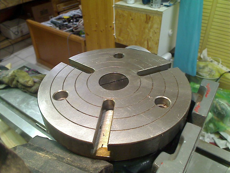
fixing the raw aluminium material on it, I could make the raw construction of my drum. here a drawing showing the geometry of the drum:
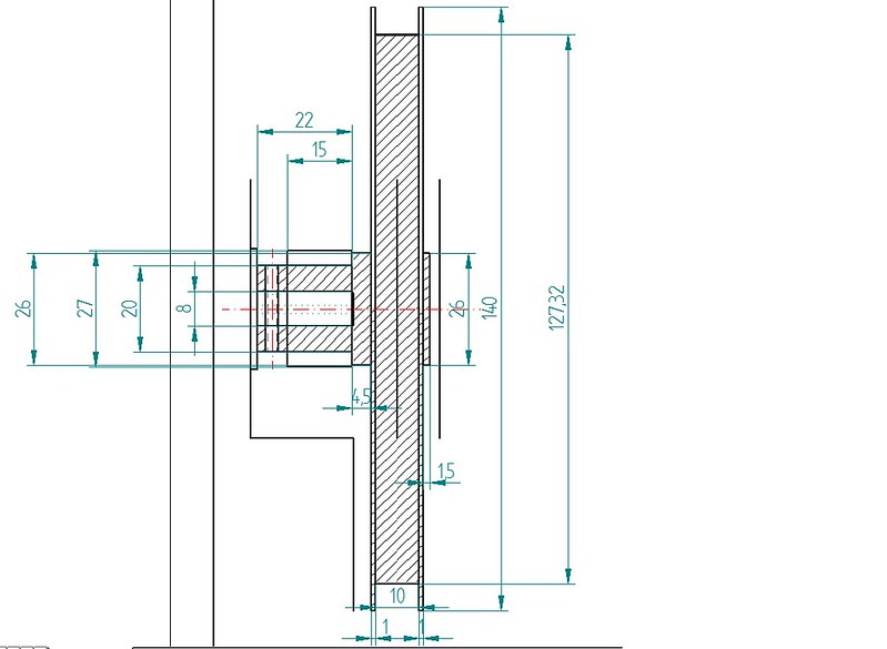
Following you can see how I started the work on the drum:
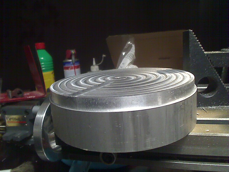
First I created a reference surface by milling one side of the raw aluminium block. Next I had to mill a circumference which had to be guaranteed perpendicular to the reference surface. 2 aspects are key to this. First, the guaranteed 90� angle to the reference surface ensured that further processing steps would result in parallel or perpendicular surfaces in relationship to the reference service. The second aspect is the need to ensure the center of the circle that represents the circumference will always be the same when i mount the drum while milling it. My milling machine has a digital indicator of the position of the coordinate table on which I mount the rotating table and on which I mount the aluminium block.
04-08-2015, 12:03 AM
#9
Junior Member
Thread Starter
Join Date: Apr 2015
Posts: 11
Likes: 0
Received 0 Likes
on
0 Posts
By storing the center position with the values (0,0) and only moving along one axis, the X-Axis to mill the circumference shown I had the guarantee that the location (0,0) was the actual center of the circumference and keeping the milling machine switched on and the rotary table at its position while I milled that circumference I could continue milling concentric circles around that center.
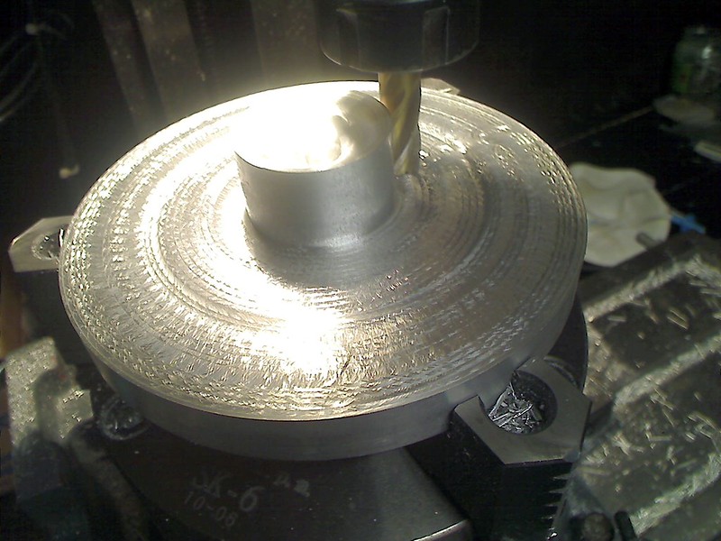
Here you can see the progress during those milling operations! Here I did an error that I have not yet fixed! Aluminium is a relatively soft metal and so a cylinder had to be applied that would be more robust. First I had planned to use ball bearings that I would mount on a cylinder made out of gunmetal. Than taking into account the required tolerances to have this drum later be mounted within an aluminium case y decided to switch from a ball-bearing to plain bearings and I learned that gunmetal had good gliding behaviour. So I decided to mount a cylinder made of gunmetal onto the aluminium shaft of the drum:
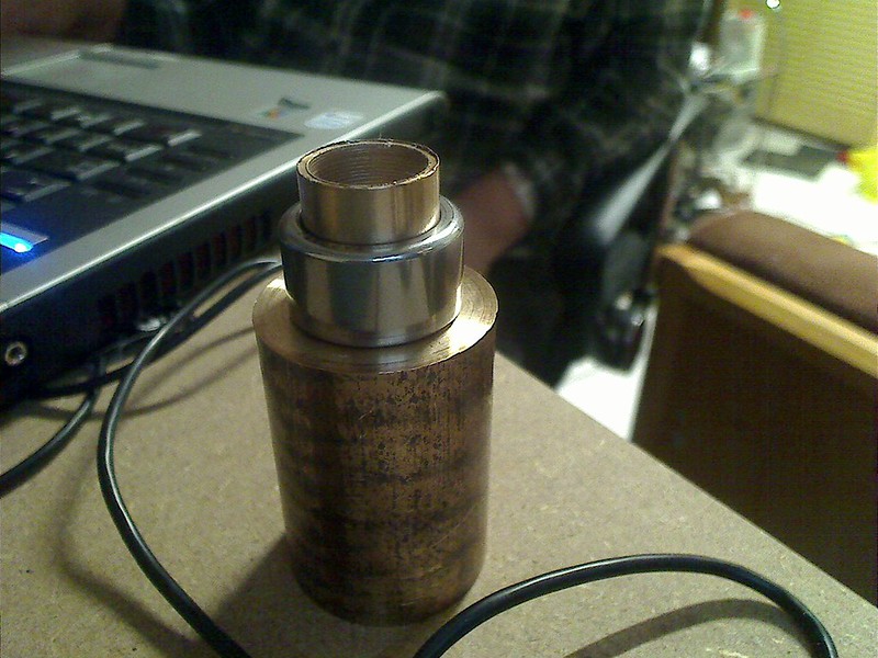

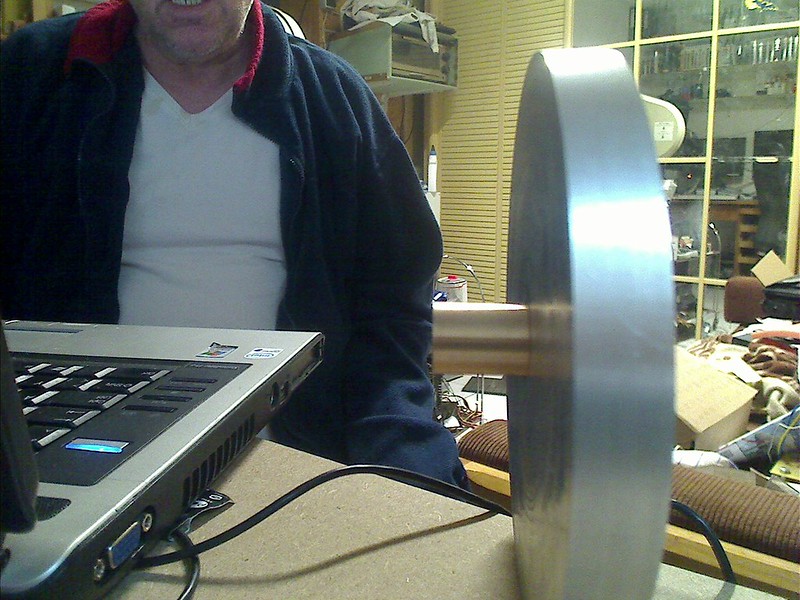
My mistake was and is, that in a sliding bearing the inner part of it has to be of a material harder that that of the outer sliding ring! Here I found that neither my lathe nor my milling machine were able to make a cylinder out of steel. So I will have to have this cylinder made by somebody else!
The next side effects of my decision to implement a sheet control system based on the use of a stepper motor resulted from my first analysis of the power consumption of a stepper motor. It happens to be that the largest amount of current flows through the coils of the motor when it keeps its position! One effect of this is, that in this moment the stepper motor has the highest torque, but the negative side is that in this state the stepper motor consumes the highest amounts of current! Thinking about the sail control while navigating I came to the conclusion that probably the sheet is kept at a constant length over the largest share of time. This is the case when the sailboat moves along a track and keeps the sail in a fixed position! My concern was that what ever solution I would end up with I should be able to navigate my sailboat at least during one full day, maybe reloading the batteries a bit during lunch break! So without any data about the real power consumption and knowing I would need stepper motors with at least 5 Nm torque, I decided to have batteries in my hull of the largest capacity that I could make to fit. Further in those early days I decided to use a mechanical break to keep the motor in a position while being able to disconnect the power supply of to reduce the power supply to the stepper motor to the lowest possible level. Those mechanical breaks release when a tension of 24 VDC is applied, while not consuming any energy while holding the shaft of the stepper motor in its actual position! Under the perspective of what was available then and to my knowledge then those mechanical breaks were the ideal complement to my stepper motors as it would eliminate the power consumption of them while holding! For the electronics the releasing of the breaks by applying those 24 VDC was a no brainer! But one of the consequences to my battery pack on board of the sailboat was that even when the batteries were reaching the point were they had to be reloaded, they had to be able to supply 24 VDC required to change the position of the sails! This resulted in having to have 12 cells connected in series, as each empty cell would still supply a bit more than 2 VDC, 12 * 2 VDc = 24 VDC, the required tension for the breaks! This combined with the fact that to be sure my sailboat would be able to operate at least a full day resulted in my choice to use headway cells, each with 16 Ah capacity! From today's perspective, knowledge and advances in the technology of stepper motor control ICs makes the size of the battery pack in my sailboat exaggeratedly big! But as my design has progressed so far that the weight of those battery cells add to the goal of getting the lowest possible center of gravity of my sailboat and besides being exaggeratedly big and offer an unlimited seeming capacity I am sticking with them!
So the first result of the above was, that to use a drum with the highest possible diameter, see sketch above, the stepper motor could no be placed at the bottom of the hull, but high enough for the drum and its future case to fits in the hull and below the deck. Linked to this was the fact that the drum would be mounted in such a way that its orientation would be perpendicular to the middle axis of the hull! Later I found out that chosen diameter for the drum resulted in a case that just fitted below the deck.
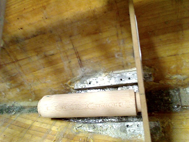
I also found that the resulting center of gravity achievable would be lower if I split the battery cell compartment in half, just 6 of them per compartment and that the stepper motor could be mounted on the top wall of such battery compartments. As a result nothing spoke against using separate stepper motors, one for the main sail, one for the fock sail and that both stepper motors could be controlled in the same manner if the fock sail also had a boom that was fixed on the deck and rotating around a vertical axis there!
This early sketch shows the comparison of the use of only one battery compartment versus two! it also shows why to add a second stepper motor became evident, as it even helped to keep the balance from front to back of the hull! Combining this with the tests by placing the battery cells fakes in the hull proved the viability of the concept.
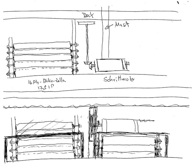
Here an early drawing of the hull and its case:
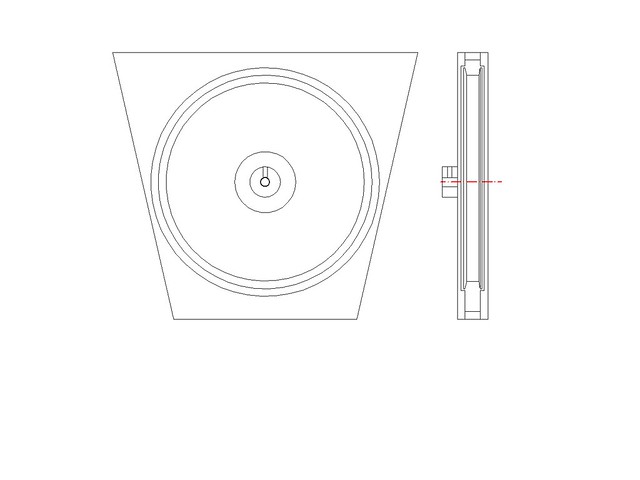
As you might remember I love to use wooden fakes as a tool to prove that concepts do actually work and fit as planned. Here you see how I was building a fake of the cases of the drums. As I owned aluminium plates, each 10 mm thick, approx. 0.4 inches I have planned to make the case for each of the drums by screwing together 2 10 mm tick halfs. The room for the drums within that cases would be milled, similar to the way I made the drum. Also I do plan to mount inserted into those walls an angular sensor, but more about the angular sensors later.
Next what I did was to make fake walls of the battery cell compartments so that combining with the fake battery cells made and presented earlier in this thread with those walls and the 2 fake drum cases I could see how well my concepts fitted into the hull:
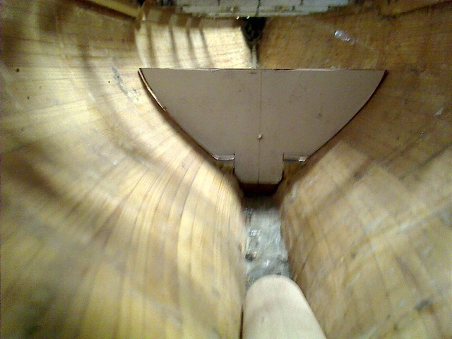
As you can see from a picture from the bottom of the hull in which I placed a fake battery cell, in the hull there was still the lead and basement I had planned for mounting the stepper motor as originally thought of. That gave me a precise reference point within the hull and I started building the corresponding wall of one of the battery compartments. As you can see it is not an easy task to make a wall that fits perfectly to the inner wall of the hull. So by using this wooden fakes I would have a starting point! It took a certain number of iterations until I got an acceptable quality wooden wall for the compartments.
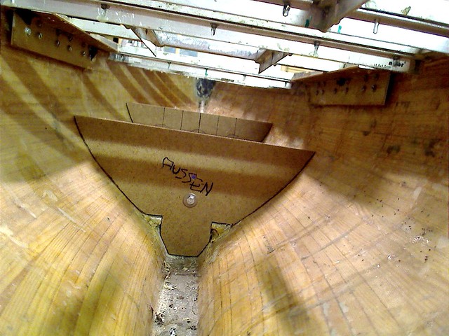
As you can see in this picture the quality of the wooden fake has improved quite a bit and you can see another wall at the rear, together they make the front battery cell compartment. But you can also see more. The upper limit of this wall has to be as low as possible, so that with the top wall of the compartment the stepper motor mounted on top does fit below the deck into the hull!
I will now continue around the topic of the battery compartments.
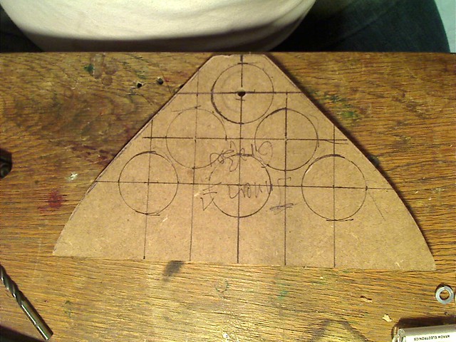
Remember that being the model a longkeeler and the sails of my model being pretty big, I have to take care not to leave any space within the hull empty, this being the more important the lower that potential free space is. The hull having the shape it has gets narrower the more you move to the front or back of it. The consequence is that a battery cell has to be placed as low and as close the others as possible being the limiting factor the wall on the narrower part of the hull. The circles drawn onto the wooden fake wall show how the battery cells are located to that wall. You can see that between the hull and the battery cells there is empty room and also between the two other battery cell levels. My plan is to place a steel sheet in such a way around the outer battery cells so that those rest on it when screwed into their positions. Between this steel sheet an the wooden walls of the hull I will use wax to get a mold that fills those empty spaces and make a form that allows me to make a leaded body of exactly the shape of those wax forms. Those will the be glued onto the walls of the hull. This has a couple of advantages. One is that it is literally impossible for water to penetrate the hull at those areas were the 2 battery cell compartments are, as the hull and the glued lead form a robust body. The same technique called "lost wax" will be used to form bodies out of lead to fill the gap between the 4 inner cells and the space between the top 3 battery cells. The final height of the wall shown will just be above the upper three battery cells so that the top cover fits on top!
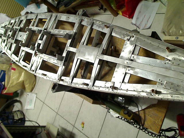
At the front part of deck shown in the above picture there is an horizontal aluminium plate with a through hole for the mast! I have placed this plate in such a way that it is 100% horizontal, parallel to the floating level of the hull, so that i.e. the mast will leave the hull through the deck perpendicular. So by making sure that plate is 100% horizontal I know I can use a spirit level to verify the cover of the battery compartments is 100% horizontal and so ensure the traversal walls have a top edge that is horizontal too!

This picture shows the 2 battery compartments, the traversal walls not yet fully adapted to the inner form of the hull. This is a real challenge as I will demonstrate later! Here two pictures I missed to show earlier:

This picture shows the raw parts I purchased to make the drums.
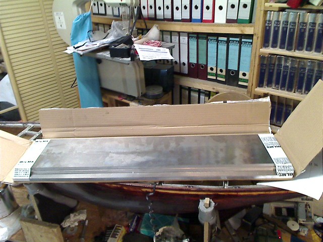
This picture shows the plates I purchased and I am using to build the battery compartments in the hull and the two cases in which the drums will be housed. So you may expect that once I have shaped the walls of the two battery compartments to perfectly match the profile of the hull internally at the exact location they belong and once i am sure that what I need to build into those walls fits as desired, then and only then can I make all 4 traversal walls of the two battery compartments and the two cased for the drums. As I have a first reference position for the rear wall of the front battery compartment, the structure existing in the bottom of the hull were I had originally planned to have the stepper motor placed, I can start constructing that wall in aluminium!
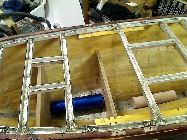
In this picture you see how I did find the exact location of the front wall of the front battery compartment. The rear wall is placed at the reference location and by the length of the battery cell the exact location of the front wall of this battery compartment can be found. It is to this location were the wall has to be perfectly adapted to the profile of the hull at that location.

This picture shows the cases for the two drums with an adapted shape placed at their final location just next to the wall that is placed at the reference location! here you see how sometimes you need the help from GOD to get that little piece of luck that is required! The 2 cases placed at their final location, position defined by the position of the wall at the reference point do exactly fit to the traversal of the labyrinth sealing! You can see, that just millimeters more to the fron of to the back would have made impossible to place the cases for the drums at their location. Such as the cases are, they are perfectly perpendicular in their positions, so that the drums that will be turning inside the final cases that are made using the aluminium plates shown, can be mounted on the stepper motors respective shafts. You can also see by looking at the shadow between the rear case and the front wall of the rear battery compartment. It is not perfectly positioned yet! There has not to be any empty space between the case and the wall! So getting the wooden fake wall there into its perfect shape will require to have the front battery compartment placed definitely into the hull and the cases to be available in aluminium!
But there are even more details that confirmed my planning! What you see in this picture are not just the 2 cases for the drums placed were they will be installed and I can you that the placement of the center hole for the shaft of the stepper motor in the case will be matched 100% with the placement of the real stepper motor shaft! Just when this construction has confirmed the location of the centerpoint of the shaft of the stepper motor I have the information to mill the hole in the cases walls so that the drums do perfectly fit!
But even more is given here! To remove one of the cases from the shaft of the corresponding stepper motor need to be able to move the case so that the shaft of the stepper motor leaves the case and I can extract the case upward! For this I have build a shape identical to the cases of the stepper motor, also 2 centimeters thick, 0.79". This shape that will be filled partly with lead can be removed upward leaving those 2 centimeters space to remove the case from the shaft of a stepper motor and so to make it possible to remove the case with the drum without removing the stepper motor! What still needs to be solved is a way to disconnect the sheet that extends through tubes within the hull below the deck in a way it does not interfere with removing or placing the drum.
As my milling machines shows problems with its shaft not being in line with the shaft of the motor and so moving a conic trayectory I have not been able to continue the work on it.
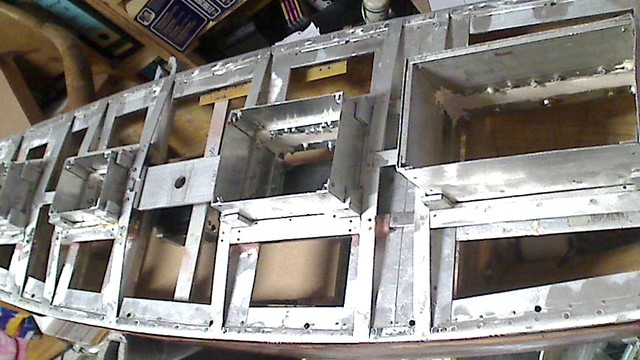
lets go step by step! In the last picture of this contribution you can kind of see the 2 stepper motors placed on top of the fake covers of both battery compartments. Its amazing, but the rear stepper motor just fits below the detachable cabin.
Here you can see the progress during those milling operations! Here I did an error that I have not yet fixed! Aluminium is a relatively soft metal and so a cylinder had to be applied that would be more robust. First I had planned to use ball bearings that I would mount on a cylinder made out of gunmetal. Than taking into account the required tolerances to have this drum later be mounted within an aluminium case y decided to switch from a ball-bearing to plain bearings and I learned that gunmetal had good gliding behaviour. So I decided to mount a cylinder made of gunmetal onto the aluminium shaft of the drum:
My mistake was and is, that in a sliding bearing the inner part of it has to be of a material harder that that of the outer sliding ring! Here I found that neither my lathe nor my milling machine were able to make a cylinder out of steel. So I will have to have this cylinder made by somebody else!
The next side effects of my decision to implement a sheet control system based on the use of a stepper motor resulted from my first analysis of the power consumption of a stepper motor. It happens to be that the largest amount of current flows through the coils of the motor when it keeps its position! One effect of this is, that in this moment the stepper motor has the highest torque, but the negative side is that in this state the stepper motor consumes the highest amounts of current! Thinking about the sail control while navigating I came to the conclusion that probably the sheet is kept at a constant length over the largest share of time. This is the case when the sailboat moves along a track and keeps the sail in a fixed position! My concern was that what ever solution I would end up with I should be able to navigate my sailboat at least during one full day, maybe reloading the batteries a bit during lunch break! So without any data about the real power consumption and knowing I would need stepper motors with at least 5 Nm torque, I decided to have batteries in my hull of the largest capacity that I could make to fit. Further in those early days I decided to use a mechanical break to keep the motor in a position while being able to disconnect the power supply of to reduce the power supply to the stepper motor to the lowest possible level. Those mechanical breaks release when a tension of 24 VDC is applied, while not consuming any energy while holding the shaft of the stepper motor in its actual position! Under the perspective of what was available then and to my knowledge then those mechanical breaks were the ideal complement to my stepper motors as it would eliminate the power consumption of them while holding! For the electronics the releasing of the breaks by applying those 24 VDC was a no brainer! But one of the consequences to my battery pack on board of the sailboat was that even when the batteries were reaching the point were they had to be reloaded, they had to be able to supply 24 VDC required to change the position of the sails! This resulted in having to have 12 cells connected in series, as each empty cell would still supply a bit more than 2 VDC, 12 * 2 VDc = 24 VDC, the required tension for the breaks! This combined with the fact that to be sure my sailboat would be able to operate at least a full day resulted in my choice to use headway cells, each with 16 Ah capacity! From today's perspective, knowledge and advances in the technology of stepper motor control ICs makes the size of the battery pack in my sailboat exaggeratedly big! But as my design has progressed so far that the weight of those battery cells add to the goal of getting the lowest possible center of gravity of my sailboat and besides being exaggeratedly big and offer an unlimited seeming capacity I am sticking with them!
So the first result of the above was, that to use a drum with the highest possible diameter, see sketch above, the stepper motor could no be placed at the bottom of the hull, but high enough for the drum and its future case to fits in the hull and below the deck. Linked to this was the fact that the drum would be mounted in such a way that its orientation would be perpendicular to the middle axis of the hull! Later I found out that chosen diameter for the drum resulted in a case that just fitted below the deck.
I also found that the resulting center of gravity achievable would be lower if I split the battery cell compartment in half, just 6 of them per compartment and that the stepper motor could be mounted on the top wall of such battery compartments. As a result nothing spoke against using separate stepper motors, one for the main sail, one for the fock sail and that both stepper motors could be controlled in the same manner if the fock sail also had a boom that was fixed on the deck and rotating around a vertical axis there!
This early sketch shows the comparison of the use of only one battery compartment versus two! it also shows why to add a second stepper motor became evident, as it even helped to keep the balance from front to back of the hull! Combining this with the tests by placing the battery cells fakes in the hull proved the viability of the concept.
Here an early drawing of the hull and its case:
As you might remember I love to use wooden fakes as a tool to prove that concepts do actually work and fit as planned. Here you see how I was building a fake of the cases of the drums. As I owned aluminium plates, each 10 mm thick, approx. 0.4 inches I have planned to make the case for each of the drums by screwing together 2 10 mm tick halfs. The room for the drums within that cases would be milled, similar to the way I made the drum. Also I do plan to mount inserted into those walls an angular sensor, but more about the angular sensors later.
Next what I did was to make fake walls of the battery cell compartments so that combining with the fake battery cells made and presented earlier in this thread with those walls and the 2 fake drum cases I could see how well my concepts fitted into the hull:
As you can see from a picture from the bottom of the hull in which I placed a fake battery cell, in the hull there was still the lead and basement I had planned for mounting the stepper motor as originally thought of. That gave me a precise reference point within the hull and I started building the corresponding wall of one of the battery compartments. As you can see it is not an easy task to make a wall that fits perfectly to the inner wall of the hull. So by using this wooden fakes I would have a starting point! It took a certain number of iterations until I got an acceptable quality wooden wall for the compartments.
As you can see in this picture the quality of the wooden fake has improved quite a bit and you can see another wall at the rear, together they make the front battery cell compartment. But you can also see more. The upper limit of this wall has to be as low as possible, so that with the top wall of the compartment the stepper motor mounted on top does fit below the deck into the hull!
I will now continue around the topic of the battery compartments.
Remember that being the model a longkeeler and the sails of my model being pretty big, I have to take care not to leave any space within the hull empty, this being the more important the lower that potential free space is. The hull having the shape it has gets narrower the more you move to the front or back of it. The consequence is that a battery cell has to be placed as low and as close the others as possible being the limiting factor the wall on the narrower part of the hull. The circles drawn onto the wooden fake wall show how the battery cells are located to that wall. You can see that between the hull and the battery cells there is empty room and also between the two other battery cell levels. My plan is to place a steel sheet in such a way around the outer battery cells so that those rest on it when screwed into their positions. Between this steel sheet an the wooden walls of the hull I will use wax to get a mold that fills those empty spaces and make a form that allows me to make a leaded body of exactly the shape of those wax forms. Those will the be glued onto the walls of the hull. This has a couple of advantages. One is that it is literally impossible for water to penetrate the hull at those areas were the 2 battery cell compartments are, as the hull and the glued lead form a robust body. The same technique called "lost wax" will be used to form bodies out of lead to fill the gap between the 4 inner cells and the space between the top 3 battery cells. The final height of the wall shown will just be above the upper three battery cells so that the top cover fits on top!
At the front part of deck shown in the above picture there is an horizontal aluminium plate with a through hole for the mast! I have placed this plate in such a way that it is 100% horizontal, parallel to the floating level of the hull, so that i.e. the mast will leave the hull through the deck perpendicular. So by making sure that plate is 100% horizontal I know I can use a spirit level to verify the cover of the battery compartments is 100% horizontal and so ensure the traversal walls have a top edge that is horizontal too!
This picture shows the 2 battery compartments, the traversal walls not yet fully adapted to the inner form of the hull. This is a real challenge as I will demonstrate later! Here two pictures I missed to show earlier:
This picture shows the raw parts I purchased to make the drums.
This picture shows the plates I purchased and I am using to build the battery compartments in the hull and the two cases in which the drums will be housed. So you may expect that once I have shaped the walls of the two battery compartments to perfectly match the profile of the hull internally at the exact location they belong and once i am sure that what I need to build into those walls fits as desired, then and only then can I make all 4 traversal walls of the two battery compartments and the two cased for the drums. As I have a first reference position for the rear wall of the front battery compartment, the structure existing in the bottom of the hull were I had originally planned to have the stepper motor placed, I can start constructing that wall in aluminium!
In this picture you see how I did find the exact location of the front wall of the front battery compartment. The rear wall is placed at the reference location and by the length of the battery cell the exact location of the front wall of this battery compartment can be found. It is to this location were the wall has to be perfectly adapted to the profile of the hull at that location.
This picture shows the cases for the two drums with an adapted shape placed at their final location just next to the wall that is placed at the reference location! here you see how sometimes you need the help from GOD to get that little piece of luck that is required! The 2 cases placed at their final location, position defined by the position of the wall at the reference point do exactly fit to the traversal of the labyrinth sealing! You can see, that just millimeters more to the fron of to the back would have made impossible to place the cases for the drums at their location. Such as the cases are, they are perfectly perpendicular in their positions, so that the drums that will be turning inside the final cases that are made using the aluminium plates shown, can be mounted on the stepper motors respective shafts. You can also see by looking at the shadow between the rear case and the front wall of the rear battery compartment. It is not perfectly positioned yet! There has not to be any empty space between the case and the wall! So getting the wooden fake wall there into its perfect shape will require to have the front battery compartment placed definitely into the hull and the cases to be available in aluminium!
But there are even more details that confirmed my planning! What you see in this picture are not just the 2 cases for the drums placed were they will be installed and I can you that the placement of the center hole for the shaft of the stepper motor in the case will be matched 100% with the placement of the real stepper motor shaft! Just when this construction has confirmed the location of the centerpoint of the shaft of the stepper motor I have the information to mill the hole in the cases walls so that the drums do perfectly fit!
But even more is given here! To remove one of the cases from the shaft of the corresponding stepper motor need to be able to move the case so that the shaft of the stepper motor leaves the case and I can extract the case upward! For this I have build a shape identical to the cases of the stepper motor, also 2 centimeters thick, 0.79". This shape that will be filled partly with lead can be removed upward leaving those 2 centimeters space to remove the case from the shaft of a stepper motor and so to make it possible to remove the case with the drum without removing the stepper motor! What still needs to be solved is a way to disconnect the sheet that extends through tubes within the hull below the deck in a way it does not interfere with removing or placing the drum.
As my milling machines shows problems with its shaft not being in line with the shaft of the motor and so moving a conic trayectory I have not been able to continue the work on it.
lets go step by step! In the last picture of this contribution you can kind of see the 2 stepper motors placed on top of the fake covers of both battery compartments. Its amazing, but the rear stepper motor just fits below the detachable cabin.
04-08-2015, 12:06 AM
#10
Junior Member
Thread Starter
Join Date: Apr 2015
Posts: 11
Likes: 0
Received 0 Likes
on
0 Posts

As you can see from the date in the picture this work on my model has taken place already a couple of years ago! The reason I present this picture has to do with the details about the battery compartments I want to present to you. You have here next to each other a fake and a real battery cell, the fake battery cell still not with the lead encrusted in it so that the fake battery weighs exactly the same as the real battery! The poles of the battery have a screw so that the current flows via those screws to the circuit that is fed by the batteries! This means the screws are conductive and have current flowing through them and the poles of the battery cells to give access to the battery cell poles. Now I have told you that the final walls will be made out of aluminium, a conductive material. So the battery cells have to be placed in the compartments with the guarantee that they will never cause a short circuit! A short circuit means that huge amounts of current flow and in combination with the electrical resistance they meet heat will generate! The battery cells being stored in those battery compartments cannot be extracted easily and as a consequence will have to be loaded and stored in those battery compartments. Also it is not out of this world that short circuits can happen.
Now the Headway battery cell I use can supply continuously up to 160 A of current and when short circuited that current flow can reach up to 240 A! So as you can imagine here is a huge source of potential problems and so a lot of attention has to be spend to prevent any accident that would destroy a sailboat that took years if not decades to be build! lets us begin looking into how much energy is stored in those 12 cells in my model! The equation for energy is:
P = V * A
Energy means "P" equals the result of the multiplication of voltage by current.
12 battery cells * 3.3 VDC = 39,6 VDC (Batteries fully loaded
Current in case of short circuit = 240 A
P [Watt] = 39,6 VDC * 240 A = 864 Watt
This amount of energy could be flowing during up to 4 minutes to unload all the energy stored in the battery cells! You got a great heater and the ship will burn, at least!
So I started to study about the stability of the different lithium based battery chemistries and their energy density, another word for the capacity of those battery chemistries. The result was that while LIfePO$ chemistry based cells do have less energy density than other lithium based chemistries, their stability was close to that known to have NiMH batteries! For this reason I decided to chose LiFePO4 battery cells!
The next issue is the dynamic behaviour of batteries and I learned about the tendency they have to shift their voltages to higher or lower values than the default one. As old fashioned battery chargers control their charging process by monitoring the voltage and current across a whole battery pack with the consequence that some cells in a pack are always kept lees than fully loaded and others end up overloaded while loading a battery pack. The same effect and danger happens while unloading a battery, what happens when you are powering a model using such a battery pack! While some cells get overly discharged, others never make available all their capacity. The result is that chargers for battery packs based on lithium chemistries today all have a so called "balancer". This balancer measures the voltage supplied by each individual cells in a battery pack and this way the charger can ensure that when fully loading a battery pack all ells are charged to the same voltage. For this a cable has t go from the connection between cells connected in series to a connector that feeds the monitoring circuits n a balancer with the actual voltages of each cell. As the so called drift of the battery cell voltages happens relatively slow, no provision is found to monitor cell voltage levels during the discharge of a battery pack.
But there is something called "BMS", "Battery Monitoring System" that monitors the individual battery cells of a battery pack while they are being used or stored. In both cases the voltage of the battery cells drops and the BMS makes sure no cell is unloaded excessively!
I have decided to use a charger a charger from a german company that implements the balancing circuitry using the LT6802-1 with a circuitry that is the 100% replica of the application note made available by the IC component supplier Linear Technology. The pdf documents that shows the circuitry is found here!
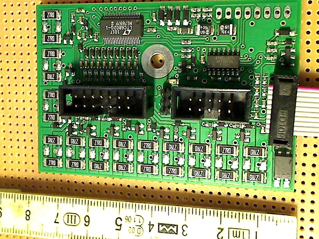
This circuit allows to monitor up to 12 cells and is used by my battery charger to balance the cells of my 12 in series connected battery cells. The same circuit and I purchased an additional one can make the function of the BMS. So I will have to ensure that my battery cells in the two battery compartments can supply the signals required by the battery chargers balancer. At the same time the second card build into my model needs to monitor the cells in the battery compartments to prevent excessive discharging while my model is being operated and while it is stored.
Finally i am spending time and effort to investigate how I can interrupt a short circuit by using fuses, or saying it in a more generic way, to prevent any heating that can set my model to burn! To design a secure system to stop negative consequences of a malfunction that includes short circuits is not a trivial problem as can be seen by reports from battery packs of smartphones exploding, or even Boeing getting in trouble with their most advanced planes!
So have this in mind while continuing reading my report, as those issues are always in my mind while dealing with these battery compartments.
On this picture you can see an improved design of where the battery in a battery compartment are being placed! You can also see that the upper edge of the wall is much closer to the battery ells of the top most 3 battery cells. printed on the piece of paper I glued onto the wooden wall are the coordinates I will move the coordinate table of my milling machine to drill the holes, i.e. the center of the circles were the screw goes through and screws into the pole of a battery cell. But you can also see 4 small circles with center holes of just 3 mm diameter! here I fix aluminium bars around which I bend the steel sheet on which the individual cells rest and as a consequence are placed correctly to take the screws in its pole!
Here you can see how screws are fixing the fake batteries in their respective positions! Just to finish another view with the two stepper motors placed roughly where they will be later!
The walls being made in their final version out of aluminium the need to make a short circuit impossible to happen is great! Next you see the technical drawing how two plastic components together make it impossible for the screw in the pole of the Battery to touch the aluminium in the wall!
next you get a picture showing the 2 parts of that function:
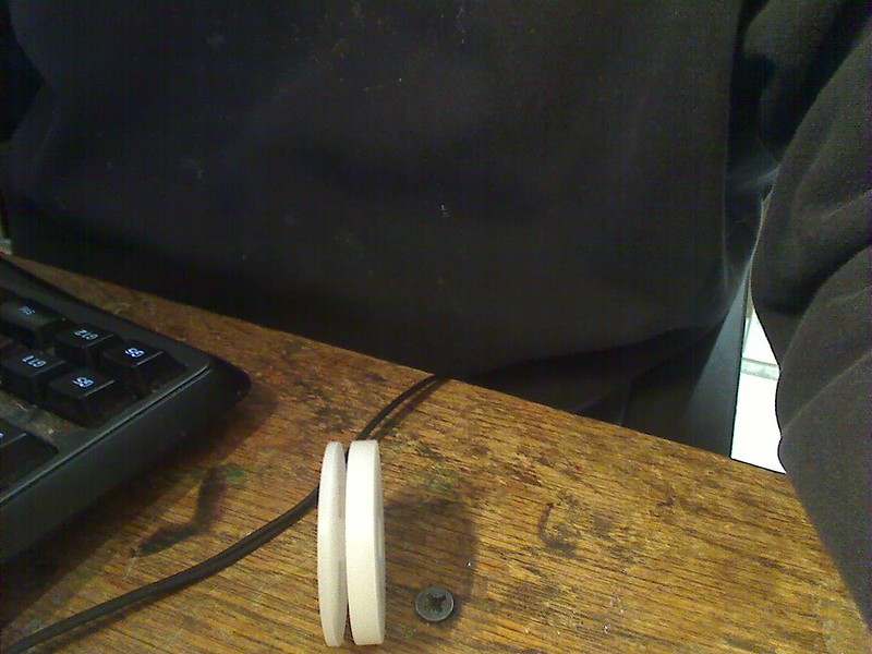
Here the two parts connected so that the screw will pass through the center hole and such be separated from the aluminium wall. The diameter of this parts is equal to the circles you have seen earlier representing the placement of the battery ells pole on the individual poles. The battery cells additionally are resting on the steel sheet that ensures physically the battery cells remain in the position defined by the through hole in the plastic parts.
Lets continue with how I milled the spaces to insert the plastic parts, first into the fake wooden wall to verify my concept. The first step was to place the rotary tables plate such that its center is directly below the milling machine axis and which corresponds to the (0,0) coordinate so that I can mill out the space to insert the plastic parts. To do so I placed the rotary table with the coordinate table of the milling machine in the center location, that is the X-coordinate and then I placed it so, that all 6 circular spaces in each wall that needed to be drilled could be reached by the axis of the milling machine, that defines were the (0,0) coordinate was in relation to the Y-axis. Than I used a plastic part I made on my lathe that has a noose with the same diameter as the holes drilled into the walls for the screws that allow to fix the battery cells in their position!
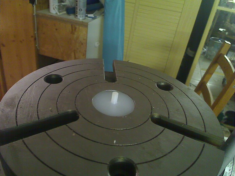
Then I placed the wall that I wanted to mill inserting the noose of the plastic part into one of the holes drilled in the centers of the circles. As the noos is lower that the 10 mm thickness of the wall all I had to do was move the coordinate table in the position were the milling and the cutter could be inserted into that hole in the wall. That location is the (0,0) coordinate of the digital display showing the coordinates for drilling.
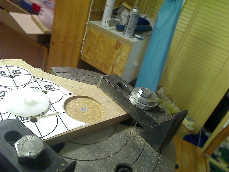
here you can see how I milled the 2 mm deep space in the wall so that the plastic part visible on the same picture fit into it and its surface was at the same altitude as the wall surface. You can also see how the plastic noose only reaches the height of the milled cavity and you can see from the images of the circles the cavities still to be milled into that fake wooden wall!

Here nearly the same picture but with the plastic part inserted into the cavity!
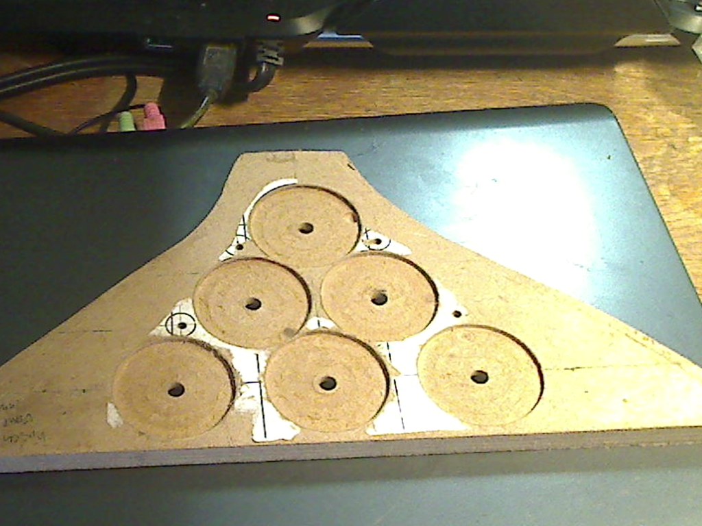
Here one of the 4 walls but with all the cavities milled!
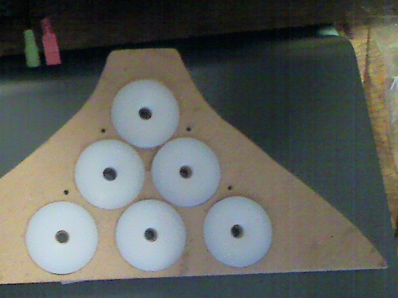
Here with the plastic parts inserted into the cavities!

This picture shows the upper of the two walls of a battery compartment with the plastic parts in the cavities of the walls, but still not with the right type of screws! You can also see that my luck of practise is responsible for not milling all cavities to the same depth. What looks like huge discrepancies actually only are fractions of a millimeter but you can see the huge impact such imperfection have visually. The next topic that became evident and the discovery of issues like that are part of the reasons to make first fake wooden parts, is the choice of the kind of screws to be selected! As you can see from the picture the heads of the screws, not to talk about the washers, my goal to have the final wall have a single flat surface, demands to use proper screws that have a head that can be fully inserted in the cavity. Also of importance is the fact of the room available for the tools to screw and unscrew the screws used to connect to the poles of the battery cells! The right screw type is one with Allen countersunk head. The tool can be adapted to only require very little space to screw and unscrew the screws. In the case of the screws for connecting the poles of the battery cells to the wall, the critical area is that in the center, were only 60 mm deep space is available. So the requirements is to be able to insert and remove the screw and to be able to fit the tool for screwing those screws on the heads of the screws in this limited space.
So lets continue showing how I fully adapted the shape of the wall at the reference location.
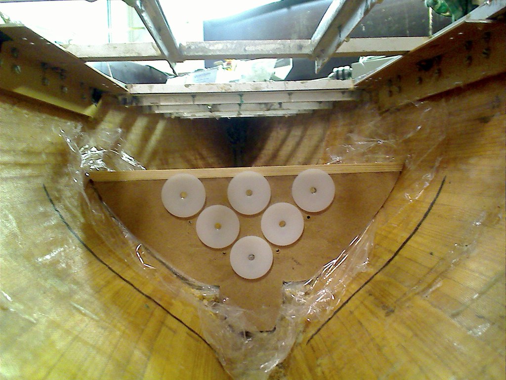
This picture is interesting in many aspects. First it shows that to achieve the perfect fit of the upper border of the wall I had to glue a wooden stick on its top. You can also see that I had to milled the cavities into the wall. The reason is, that the key objective here was to have a form that perfectly fitted into the shape of the hull at the location were this wall was to be placed. But you can see from watching the plastic parts, that their diameter which is identical to that of the real battery cells is very close below that upper border of the wall. The small distance left is the space required by the cover plate that fits on top and has milled a "step" all around it so that it is well fitting into the compartment and inserted its lower surface will be touching the upper battery cells nearly. A head conducting foam will be glued on the inner surface of the cover plate so that while the cover plate is electrically isolated from the battery cells, hear can diffuse into the cover aluminium plate. Remember that one of my goals is to ensure everything possible is done to diffuse heat that might appear in the battery cells is best possible diffused into the huge aluminium structures of the sailboat. Trying to prevent heat from being generated in case of an extreme flow of current will also show up in my design.
You can also see that i have placed a foil between the hull and the wall and that there are still gaps between the wall and the hull shape!
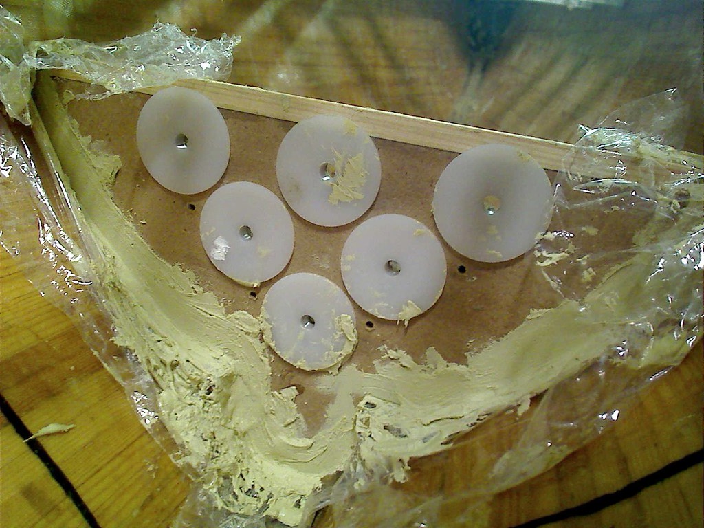
Here you can see the same wall but now all the gaps filled with filler!
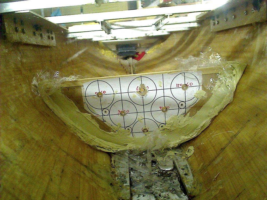
Here the same wall, but now from the other side!
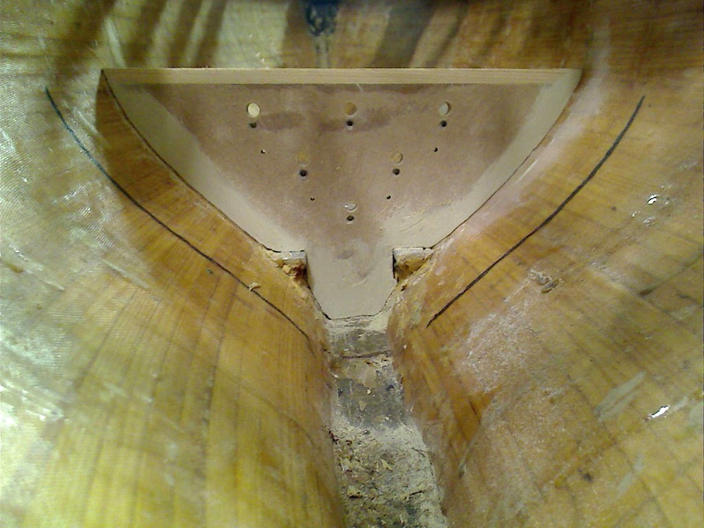
The same wall, but now showing the perfect fit to the hull. On the left side it loos like if their is a gap, but its only a shadow that lets you think so!
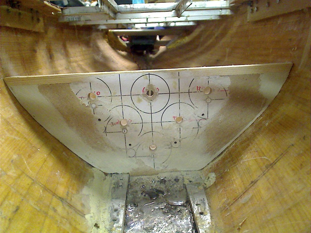
The same wall as before, but now from the other side!
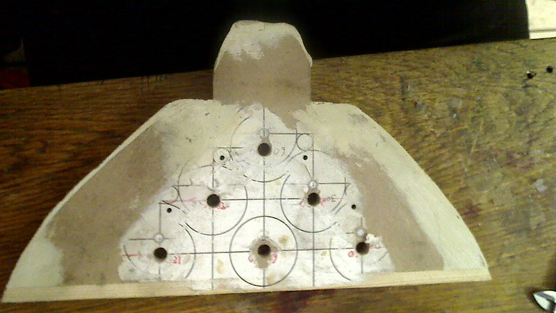
The same wall, but now finished to be used as a form to make the real aluminium version of it!
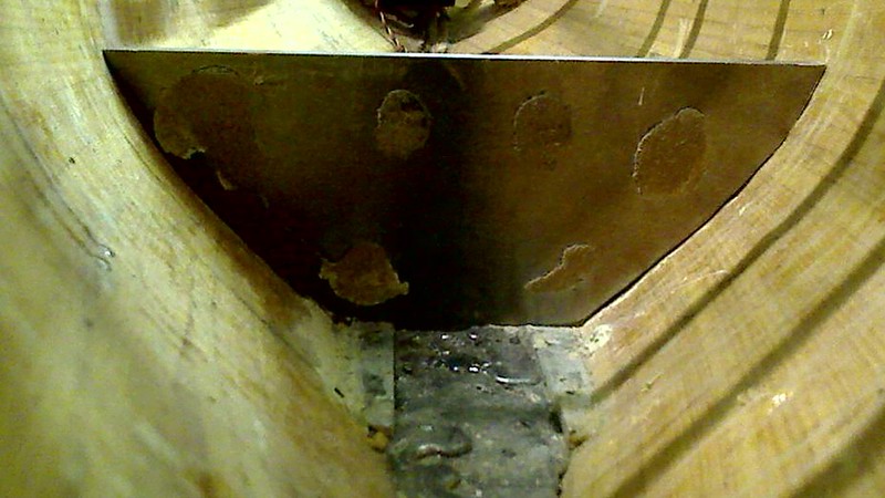
Here you see for the first time the aluminium version of the wall, still with leftovers from having glued the fale wooden wall onto the aluminium plate.
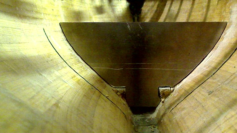
The same aluminium version of the wall from the other side. As you can see, at least for an untrained miller milling the aluminium shape of the wall having an wooden form glued onto the surface of the aluminium plate is far from perfect as can be seen by the gaps seen on the picture. Two main reasons exist for this! One is definitely the inability to mill the aluminium plate exactly enough to be shaped as the wooden form. The second even more important factor is the fact that the profile of a 10 mm thick aluminium wall does not have the same shape on both sides of the plate. The hull changes its shape enough over those 10 mm, so that the gaps are a result of this. It also proofs what I had expected, that I need to take extreme effort to shape the fake wooden versions of the walls at the very precise positions were they will be placed at the end! So manual work is required to adapt the shape of the aluminium wall to the hull shape in such a way that its upper border still is at its perfect place, so that the cover placed on top will be 100% parallel to the floating level of the sailboat!

The same way, starting from the wooden fake wall i made the second wall of the battery cell compartment. To ensure that the shape of the second wall was taken from the correct position were that second wall would be placed within the hull I screwed the fake wooden battery cells between the aluminium wall finished first and the wooden second wall that was going to be the form to make its aluminium version shown here. Very critical, besides defining its shape by ensuring the 100% correct final position of the second wall, I also had to make 100% sure that the shape of the form in its final position would result in the battery cells being fixed by screwing its pole between both walls were 100% horizontal, means parallel to the floating level plane, that its upper border resulted in a perfect parallel placement of the cover when placed on top of the battery cell compartment. It took a lot of effort to accomplish this, make the aluminium version of it and placing the holes drilled for the screws for the poles of the battery cells at its right positions. As you can well imagine changing from the fake wooden versions of the walls to their final aluminium counterparts made it impossible to insert the real battery cells in the battery compartment. Short circuits with all their possible consequences would be the result! So what I did the was to make the aluminium solid tubes for which you had seen the 3 mm diameter holes drilled into the wooden walls.
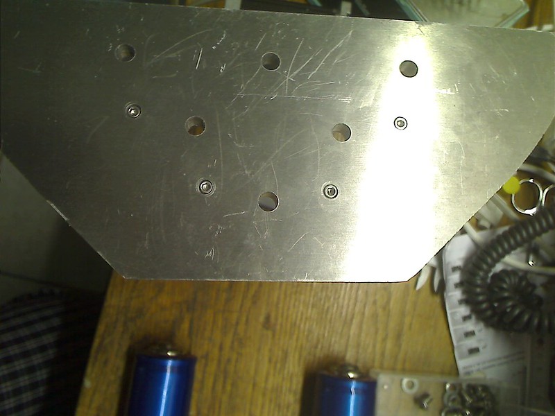
This picture shows on the second wall not just the holes drilled with the diameter of the screws for connecting to the poles of the battery cells, but also how the 3 mm diameter holes drilled for the M3 Allen cylinder head screws used to fix the aluminium bars over which the steel sheet would be bended that would form the rest for the battery cells in the compartment, at least for those hull side. as you can also see I have drilled holes with a bigger diameter so deep into the wall, that the cylinder heads fit into those cavities and lay below the surface level!
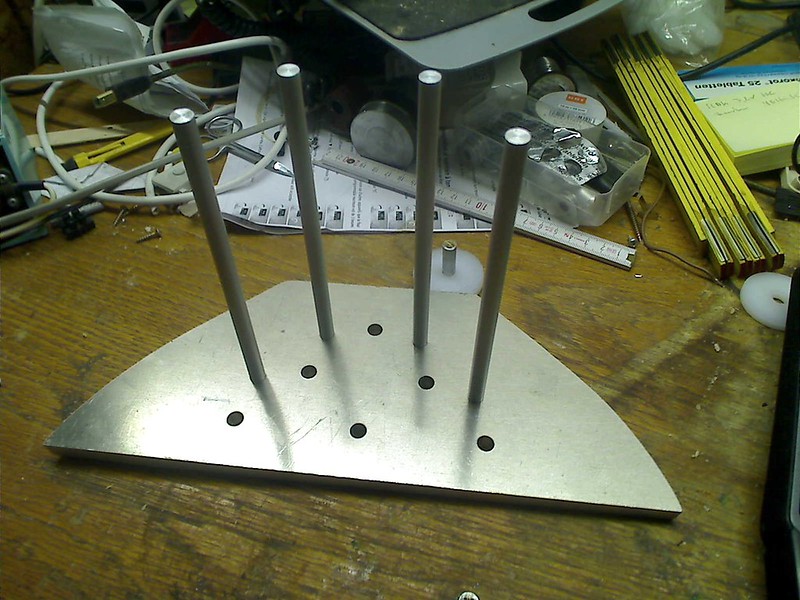 04-08-2015, 12:09 AM
#11
Junior Member
Thread Starter
Join Date: Apr 2015
Posts: 11
Likes: 0
Received 0 Likes
on
0 Posts
Here you can see the second woll with the aluminium bars screwed into their position and the cylinder heads of the screws below the surface of the wall, so that the wall can rest fully on the desktop surface!
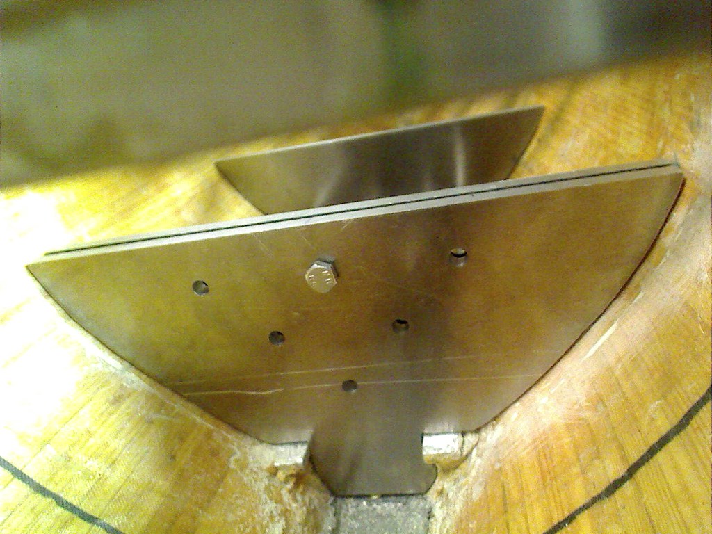
This picture of this contribution to my thread is from an earlier phase of the construction and shows both aluminium version walls, still without any holes drilled into them, but the first wall with a second wall directly fitted behind the first wall. Well, this requires some explanations and it will change some of the information supplied earlier to you! One of the objectives that I follow during my construction of the sailboat is to have most elements not glued into the hull or deck, but screwed into their positions. Well, the walls of the compartment consist of actually two plates!
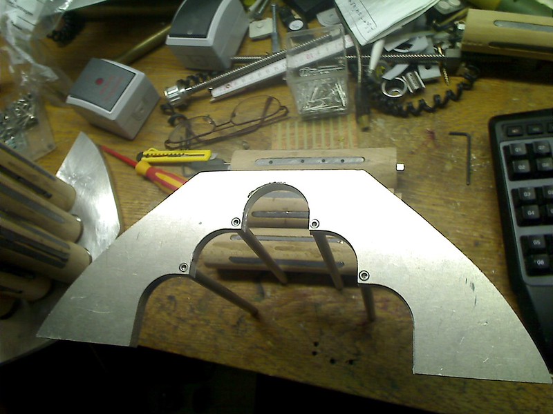
This picture shows the inner of the two plates that make up a wall of a battery compartment. You can see an aluminium structure that is perfectly shaped for the hull within the compartment next to the outer wall. Inside what has been eliminated is that part of the wall where the battery cells are and as you can see from the holes drilled for the M3 cylinder head Allen screws, the sharp corners not yet adapted to the shape of the aluminium bars screwed onto this inner wall. The steel sheet that will make the bed on which the "outer placed" battery cells rest, will rest and be screwed and glued onto this wall that will have the exact shape of the steel sheet. The aluminium bars will be screwed onto another inner wall of the same kind within the compartment and next to that second outer wall. What I still have to find out is how the length of the battery cells change when they get hot. As you well know, any material that increases its temperature changes its physical dimensions and so the compartment has to be long enough to have the battery cells fit within in case the batteries get hot, but do not yet burn! If they burn everything is over! Of course I have also already spend some thinking as to how I will make it possible for gas that might emanate from the battery cells to exit the compartment to prevent pressure from building up and eventually leading to an explosion!
I have postponed drilling the holes to screw both plates of a wall together, because for this I need to know where in the outer wall of a battery compartment I may have room to place those holes to be drilled in! Guess what, the inner structure of the outer walls of the battery cell compartment have a lot of stuff build in that I will present in my next contribution!
The picture of one of the "inner walls" of a battery cell compartment that will be glued to the hull of the model. So between the two "inner walls " of each of the two batter y cell compartments, the hull itself and the steel sheet is the room where using wax to get the exact copy of this space a number of molds made of lead will fill this pace and ensure that the center of gravity is as low as possible. The lead that fills that space will not reach to the upper level were the cover of the compartments sits, as parts of the space will be used to place electronics in it. Specially the DC/DC-converters that generate i.e. the 24 VDC supply needed for the release of the mechanical brakes and the DC/DC-converters that supply the 15 VDC I will use as the supply for the I2C-buses. This about 3x the tensi�n that bus normally has will ensure the robustness and the integrity of the data transmitted over the I2C buses. I use level converting I2C-buffers that allow to change the level from 5 VDC or 3.3 VDC used in the �controller or the temperature and humidity sensors located next to the LED lights I will be using on board. But that a completely different story I will continue and write about at the proper time! This DC/DC-converters are switching converters but still so generate heat that will be diffused into the aluminium and lead in the hull of my model!
But there is more in this story!
This graphic shows the basic circuitry required to connect the 6 battery cells in a compartment. The thick lines, black, green and red show how the 6 battery cells in a single compartment are connected in series, black being the negative pole of the resulting battery pack, red the positive pole. The thick geometry of those lines are to demonstrate that the huge amount of current will be flowing along those connections. if a short circuit happens, those thick lines will show the up to 240 A of current that might flow through those electrical links!
The fine blue lines represent those lines required to measure the actual voltage supplied by the individual battery cells. As you can see, 7 of those lines are required and have to be fed to the balancer of a charging device, but also to the BMS, Battery Monitoring System, to monitor the voltage of the individual cells during times the battery are stored, inactive, in the model and during time were power consumption takes place and those battery ells discharge! All this electrical connections have to be integrated into the wall of the battery compartment so that they do not interfere with the cases of the drums i.e.!
The two schematics show how the electrical connections are, the upper of the two schematics show the wall in the center, the lower schematic show the lines within the "outer" wall, means the front wall of the front compartment, the "rear" wall of the rear compartment. The reason for this is that I want to have the two main poles of the two battery cell compartment close to each other. Here I will place fuses that interrupt the power lines in case of a short circuit. But also here will be the large connectors for the power lines, the feeding into the DC/DC-converters placed at the sides of battery cell compartments. But also the full tension supplied by connecting both battery cell compartments in series will be fed into the two stepper motor control electronics! Additionally I am still thinking about how to realize the circuitry that intelligently routes the connections dependent on the operating status of the model! What do I mean with this?
Well, first operating mode is one were no energy is consumed within the model, ON/OFF-switch OFF, no charging takes place!
In this case the main power lines will be disconnected from the stepper motor electronics, from the DC/DC-Converters, but the BMS needs to be supplied with energy to enable it to be monitoring the battery cells and to react intelligently and adequate in case it detects i.e. the heating of a battery cell within one of the 2 battery cell compartments! An acoustic signal has to be generated by using the acoustic signal warning of my smoke detector system in my workshop that is part of my residential smoke and fire warning system! A lot of thinking will have to be invested in this at the proper time!
The next operating mode is one were the ON/OFF-switch is still OFF, but the battery cells are being loaded!
Here the main power lines have to be routed to the connectors for the charger, the BMS has to be disconnected and the sensing lines, the fine blue lines shown above have to be disconnected from the BMS and made available to the connector for the balancer in the charger.
The next operating mode is when the ON/OFF-switch is switched to ON!
I stop here describing the additional operating modes and what they mean. This will be dealt with at the proper time. Relevant is this description due to its effects on what needs to be planned, to be added and to be taken into account when deciding how to make those lines integrated into the walls of the battery cell compartments. I plan to proceed with this when I have to place the proper connecting points above the cover plates of the two compartments!
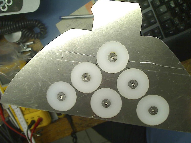
I decided to present this picture here now, as it makes it easier, so I hope to visualize what I am doing. I will present some pictures how the cavities were made for the plastic parts in the aluminium wall. As you can well imagine the screws are not holding the real battery cells in position, but the wooden fake ones! The danger of short circuiting them is to big and the battery cells in sum were quite expensive! But what you can see in this picture are the screws I will be using! This are stainless steel countersunk metric screws. They still need the diameter of the heads to be reduced a bit with my lathe, but they are already at or below the surface level of the aluminium wall! Now, I decided to use 3 mm thick copper bands to connect the poles of the batteries, or so to say to implement the "thick" connection lines in the circuitry shown above.

This picture shows in detail the stainless steel screw and the hole milled into the 3 mm thick copper band for one of the poles. The screw will be worked on in the lathe to fit into the diameter on the top of the hole to ensure it has the biggest possible electrical contact surface between the screw and the copper band. This has the effect, that the electrical resistance between the screw and the copper band is kept as low as possible and so the heat resulting from the Ohms law at his contact surface is as little as possible. Also you can see by the size of the screw and the copper band that both will have little problems to withstand even the short circuit case with a current of up to 240 A flowing through! of course I need to keep in mind the whole electrical chain, as the weakest spot will determine were maximum heat will be generated.
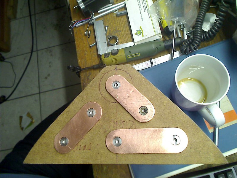
Here you can see the three copper connectors, now applied using a wooden fake wall just to get a picture of it! But what can also be seen is, that the screw heads are below the surface of the copper bands! The reason for this is related to something still open to be done for the first time. All electrical conductive materials used in the battery cell compartments will get a "Powder Coating Surface". You know the surface resulting from powder coating. Those are this plastic coatings you find on many cases. Using a gun powder is blown and loaded electrically. The object to which powder coating is applied is grounded and so the powder flies and gets deposited on those electrically grounded objects. Those objects are then placed in an owen, I have an adequate owen in my workshop and after heating it the deposited powder melts building an electrically isolating coating! So the aluminium wall, prior to integrating all the stuff I integrate into the walls will get such a powder coating as an additional protection for short circuits prevention! Same happens with these copper bands, excluding the holes were the screws need to have electrical connection.
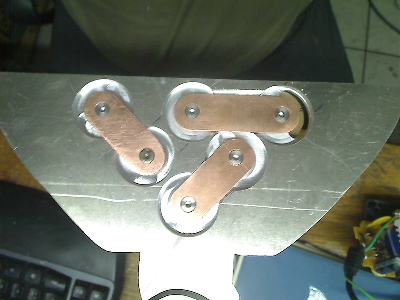
In this picture you can see, of course just using the fake battery cells, the cavities milled into the wall so that the copper bands connect the poles and are fully placed within the wall geometry! As you can well imagine and as you know that there have also to be the plastic parts inserted to prevent the copper bands to have an electric contact with the aluminium of the wall. Here my milling machines started to show that it had worn out not working as precise as I wished it did wish and needed. But you can also imagine, even if the metal parts all have a powder coating and that everything would be submerged in an epoxide bath, I had to find a textile highly resistive to high temperatures.
This picture shows the sample of such an textile I got. So between the copper bad connecting the poles of the battery cells and the aluminium of the walls I would place a piece of this textile to ensure that even when the temperature would rise to a level that attacks the epoxide, this textile would keep the copper band and the aluminium wall electrically isolated. I could not imagine to do more within the walls of the battery cell compartment to prevent by any means that the copper band and the aluminium wall could ever get electrically connected causing a catastrophic damage! The fine cables used to enable monitoring of the tension of each battery cell are much thinner and in the event of a short circuit that may have up to 240 A of current flowing through them would simply melt them away. Using teflon tubes and having those thin cables covered by heat resistant silicon isolation should prevent that short circuiting those thin cables can cause a mayor short circuit. I plan to do an experiment by melting such a fine cable applying the 160 A continuous current my battery cells can supply and ensure that the cables will melt interrupting the electrical connection! i will also further analyze the possibility to a section outside the wall were a fuse can protect the cables within the wall and the electronics of the balancer!
Due to the fact that the text length in my last contribution happen to be too long I will take the opportunity to show some more pictures!

This picture shows the copper bands placed within the aluminium wall and how there is space between the copper band and the aluminium wall. The plastic part isolating the screw and the poles of the battery cells from getting in contact with the aluminium in the walls consist of 2 parts. On is the part with the noose that surrounds the screw on its way through the wall, the second part is just a 5 mm thick plastic circular disc. As soon as my milling machine is working well again I will mill into this 5 mm thick plastic disc the cavity to receive the 3 mm thick copper band. I assume a cavity depth of 3.3 mm will be enough to deal with the powder coating thickness, the heat resistant textile and to have the copper band be at or below the surface of the powder coated aluminium wall.
What I have not yet even started to do is to mill the "channels for the cables to the balancing electronics. Besides that I only want to start doing so when the final placement of the copperbands is done, I need to decide about how to make the connection to a balancer and BMS connectors. For example those fine copper cables need to be stable enough to allow to mount and unmount the cover of the Compartment as frequently as possible. i am thinking about having a brass tube around them and have the 7 cables leave physically close to each other so that a stronger connector can ensure the mechanical stability. I am still investigating how to do this, but with low priority!
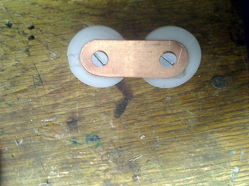
Here a picture that shows a first try in milling out the cavity of the plastic part to place the copper band in it!
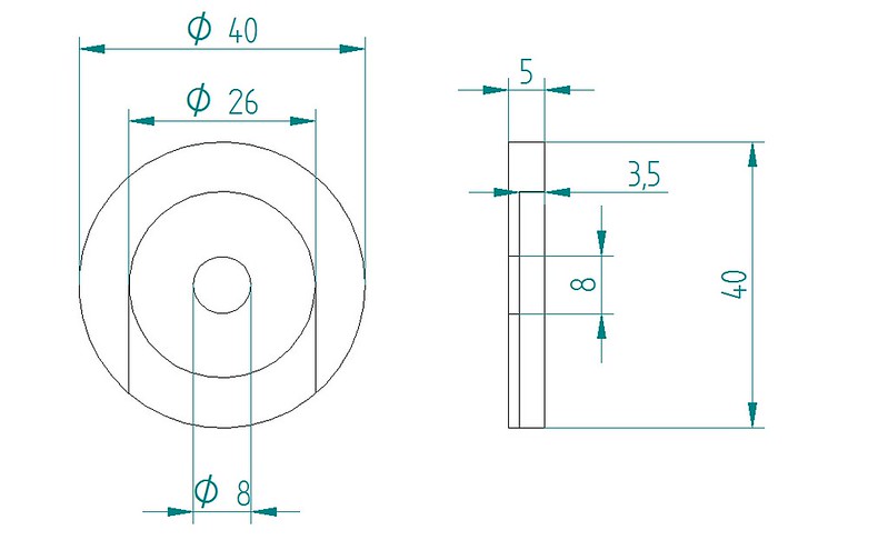
The second technical drawing shows the dimensions i plan to apply to mill the cavities for the copper bands!
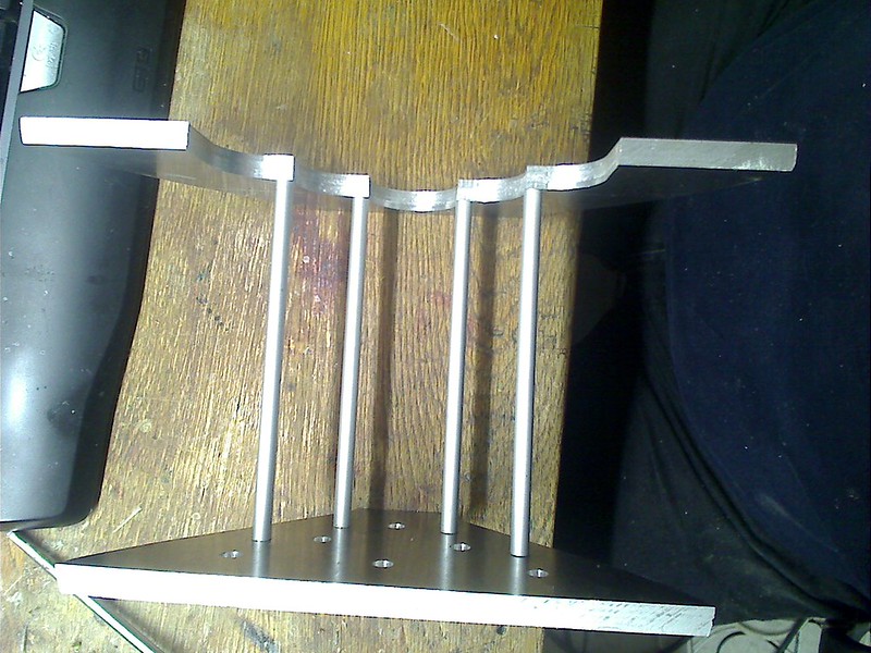
Here a picture that shows the "inner wall" that will be glued to the hull with the aluminium bars screwed into position and what will be the inner wall of the second wall in this battery cell compartment, but not yet milled as the other inner wall. As I wrote earlier, I still need to investigate what extra length I need to make available for the battery cell when it gets heated to prevent the compartment to be destroyed by the stretching battery cells! Only then I will now in to the last detail exactly the position to which this inner wall has to fit and then to be glued to the hull, as soon as I know whre the screws to mount the outer wall to the inner wall can be placed!
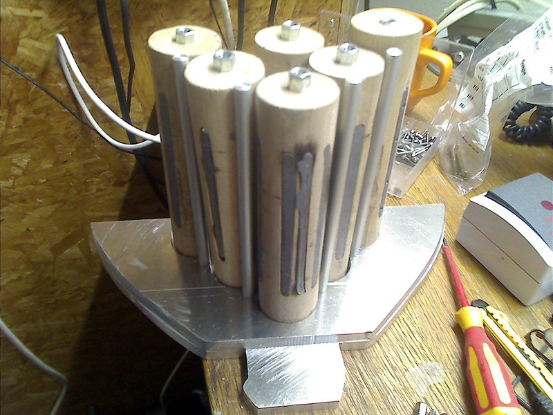
Here you can see both of the rear wall, the inner and the outer wall of the front battery cell compartment with the aluminium bars, still a bit long so that I can decide about their final length! I also think that with the fake battery cells screwed into their positions it gets evident how the steel sheet, also powder coated, will bend around the outer battery cells and the aluminium bars! You also see, as I have to confess, the shape of the outer and inner wall are quite different and that some extra work will be required. But the inner wall will be glued to the hull, so that gaps will be filled by the glue. Besides, the inner wall will be hidden from sight by the outer wall when this outer wall is screws to the inner wall!
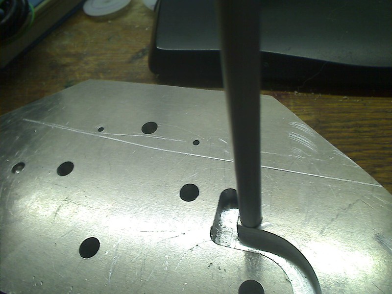
This picture allows to see how the inner wall got its inner parts removed by milling! I use the holes for the screws with the noose from the plastic part to set the (0,0) coordinate of the digital indicator of the coordinate table and can so combining the function of the rotary table and the milling machine digital indicator to track the milling as desired!
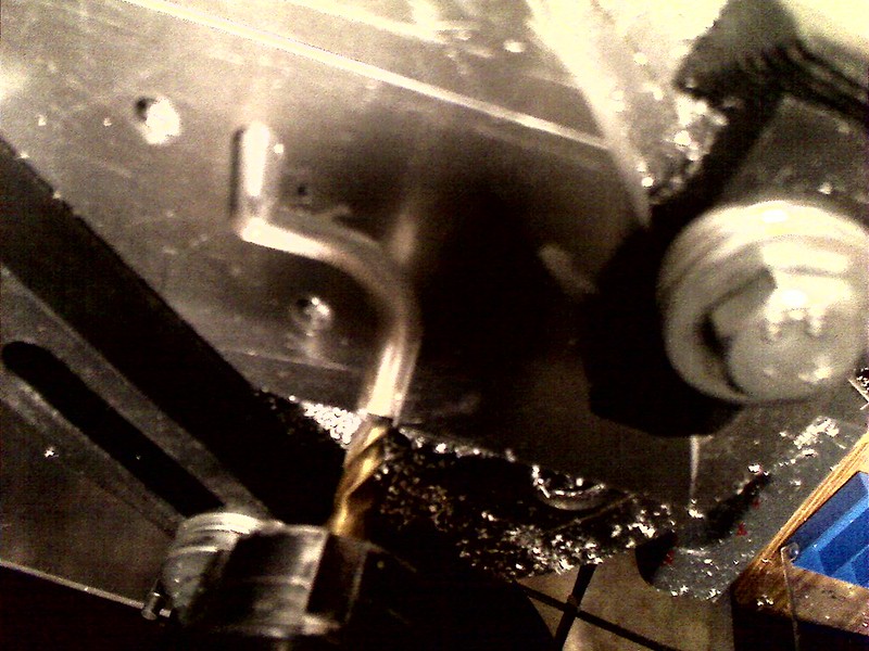
This picture of this contribution to my thread is from an earlier phase of the construction and shows both aluminium version walls, still without any holes drilled into them, but the first wall with a second wall directly fitted behind the first wall. Well, this requires some explanations and it will change some of the information supplied earlier to you! One of the objectives that I follow during my construction of the sailboat is to have most elements not glued into the hull or deck, but screwed into their positions. Well, the walls of the compartment consist of actually two plates!
This picture shows the inner of the two plates that make up a wall of a battery compartment. You can see an aluminium structure that is perfectly shaped for the hull within the compartment next to the outer wall. Inside what has been eliminated is that part of the wall where the battery cells are and as you can see from the holes drilled for the M3 cylinder head Allen screws, the sharp corners not yet adapted to the shape of the aluminium bars screwed onto this inner wall. The steel sheet that will make the bed on which the "outer placed" battery cells rest, will rest and be screwed and glued onto this wall that will have the exact shape of the steel sheet. The aluminium bars will be screwed onto another inner wall of the same kind within the compartment and next to that second outer wall. What I still have to find out is how the length of the battery cells change when they get hot. As you well know, any material that increases its temperature changes its physical dimensions and so the compartment has to be long enough to have the battery cells fit within in case the batteries get hot, but do not yet burn! If they burn everything is over! Of course I have also already spend some thinking as to how I will make it possible for gas that might emanate from the battery cells to exit the compartment to prevent pressure from building up and eventually leading to an explosion!
I have postponed drilling the holes to screw both plates of a wall together, because for this I need to know where in the outer wall of a battery compartment I may have room to place those holes to be drilled in! Guess what, the inner structure of the outer walls of the battery cell compartment have a lot of stuff build in that I will present in my next contribution!
The picture of one of the "inner walls" of a battery cell compartment that will be glued to the hull of the model. So between the two "inner walls " of each of the two batter y cell compartments, the hull itself and the steel sheet is the room where using wax to get the exact copy of this space a number of molds made of lead will fill this pace and ensure that the center of gravity is as low as possible. The lead that fills that space will not reach to the upper level were the cover of the compartments sits, as parts of the space will be used to place electronics in it. Specially the DC/DC-converters that generate i.e. the 24 VDC supply needed for the release of the mechanical brakes and the DC/DC-converters that supply the 15 VDC I will use as the supply for the I2C-buses. This about 3x the tensi�n that bus normally has will ensure the robustness and the integrity of the data transmitted over the I2C buses. I use level converting I2C-buffers that allow to change the level from 5 VDC or 3.3 VDC used in the �controller or the temperature and humidity sensors located next to the LED lights I will be using on board. But that a completely different story I will continue and write about at the proper time! This DC/DC-converters are switching converters but still so generate heat that will be diffused into the aluminium and lead in the hull of my model!
But there is more in this story!
This graphic shows the basic circuitry required to connect the 6 battery cells in a compartment. The thick lines, black, green and red show how the 6 battery cells in a single compartment are connected in series, black being the negative pole of the resulting battery pack, red the positive pole. The thick geometry of those lines are to demonstrate that the huge amount of current will be flowing along those connections. if a short circuit happens, those thick lines will show the up to 240 A of current that might flow through those electrical links!
The fine blue lines represent those lines required to measure the actual voltage supplied by the individual battery cells. As you can see, 7 of those lines are required and have to be fed to the balancer of a charging device, but also to the BMS, Battery Monitoring System, to monitor the voltage of the individual cells during times the battery are stored, inactive, in the model and during time were power consumption takes place and those battery ells discharge! All this electrical connections have to be integrated into the wall of the battery compartment so that they do not interfere with the cases of the drums i.e.!
The two schematics show how the electrical connections are, the upper of the two schematics show the wall in the center, the lower schematic show the lines within the "outer" wall, means the front wall of the front compartment, the "rear" wall of the rear compartment. The reason for this is that I want to have the two main poles of the two battery cell compartment close to each other. Here I will place fuses that interrupt the power lines in case of a short circuit. But also here will be the large connectors for the power lines, the feeding into the DC/DC-converters placed at the sides of battery cell compartments. But also the full tension supplied by connecting both battery cell compartments in series will be fed into the two stepper motor control electronics! Additionally I am still thinking about how to realize the circuitry that intelligently routes the connections dependent on the operating status of the model! What do I mean with this?
Well, first operating mode is one were no energy is consumed within the model, ON/OFF-switch OFF, no charging takes place!
In this case the main power lines will be disconnected from the stepper motor electronics, from the DC/DC-Converters, but the BMS needs to be supplied with energy to enable it to be monitoring the battery cells and to react intelligently and adequate in case it detects i.e. the heating of a battery cell within one of the 2 battery cell compartments! An acoustic signal has to be generated by using the acoustic signal warning of my smoke detector system in my workshop that is part of my residential smoke and fire warning system! A lot of thinking will have to be invested in this at the proper time!
The next operating mode is one were the ON/OFF-switch is still OFF, but the battery cells are being loaded!
Here the main power lines have to be routed to the connectors for the charger, the BMS has to be disconnected and the sensing lines, the fine blue lines shown above have to be disconnected from the BMS and made available to the connector for the balancer in the charger.
The next operating mode is when the ON/OFF-switch is switched to ON!
I stop here describing the additional operating modes and what they mean. This will be dealt with at the proper time. Relevant is this description due to its effects on what needs to be planned, to be added and to be taken into account when deciding how to make those lines integrated into the walls of the battery cell compartments. I plan to proceed with this when I have to place the proper connecting points above the cover plates of the two compartments!
I decided to present this picture here now, as it makes it easier, so I hope to visualize what I am doing. I will present some pictures how the cavities were made for the plastic parts in the aluminium wall. As you can well imagine the screws are not holding the real battery cells in position, but the wooden fake ones! The danger of short circuiting them is to big and the battery cells in sum were quite expensive! But what you can see in this picture are the screws I will be using! This are stainless steel countersunk metric screws. They still need the diameter of the heads to be reduced a bit with my lathe, but they are already at or below the surface level of the aluminium wall! Now, I decided to use 3 mm thick copper bands to connect the poles of the batteries, or so to say to implement the "thick" connection lines in the circuitry shown above.
This picture shows in detail the stainless steel screw and the hole milled into the 3 mm thick copper band for one of the poles. The screw will be worked on in the lathe to fit into the diameter on the top of the hole to ensure it has the biggest possible electrical contact surface between the screw and the copper band. This has the effect, that the electrical resistance between the screw and the copper band is kept as low as possible and so the heat resulting from the Ohms law at his contact surface is as little as possible. Also you can see by the size of the screw and the copper band that both will have little problems to withstand even the short circuit case with a current of up to 240 A flowing through! of course I need to keep in mind the whole electrical chain, as the weakest spot will determine were maximum heat will be generated.
Here you can see the three copper connectors, now applied using a wooden fake wall just to get a picture of it! But what can also be seen is, that the screw heads are below the surface of the copper bands! The reason for this is related to something still open to be done for the first time. All electrical conductive materials used in the battery cell compartments will get a "Powder Coating Surface". You know the surface resulting from powder coating. Those are this plastic coatings you find on many cases. Using a gun powder is blown and loaded electrically. The object to which powder coating is applied is grounded and so the powder flies and gets deposited on those electrically grounded objects. Those objects are then placed in an owen, I have an adequate owen in my workshop and after heating it the deposited powder melts building an electrically isolating coating! So the aluminium wall, prior to integrating all the stuff I integrate into the walls will get such a powder coating as an additional protection for short circuits prevention! Same happens with these copper bands, excluding the holes were the screws need to have electrical connection.
In this picture you can see, of course just using the fake battery cells, the cavities milled into the wall so that the copper bands connect the poles and are fully placed within the wall geometry! As you can well imagine and as you know that there have also to be the plastic parts inserted to prevent the copper bands to have an electric contact with the aluminium of the wall. Here my milling machines started to show that it had worn out not working as precise as I wished it did wish and needed. But you can also imagine, even if the metal parts all have a powder coating and that everything would be submerged in an epoxide bath, I had to find a textile highly resistive to high temperatures.
This picture shows the sample of such an textile I got. So between the copper bad connecting the poles of the battery cells and the aluminium of the walls I would place a piece of this textile to ensure that even when the temperature would rise to a level that attacks the epoxide, this textile would keep the copper band and the aluminium wall electrically isolated. I could not imagine to do more within the walls of the battery cell compartment to prevent by any means that the copper band and the aluminium wall could ever get electrically connected causing a catastrophic damage! The fine cables used to enable monitoring of the tension of each battery cell are much thinner and in the event of a short circuit that may have up to 240 A of current flowing through them would simply melt them away. Using teflon tubes and having those thin cables covered by heat resistant silicon isolation should prevent that short circuiting those thin cables can cause a mayor short circuit. I plan to do an experiment by melting such a fine cable applying the 160 A continuous current my battery cells can supply and ensure that the cables will melt interrupting the electrical connection! i will also further analyze the possibility to a section outside the wall were a fuse can protect the cables within the wall and the electronics of the balancer!
Due to the fact that the text length in my last contribution happen to be too long I will take the opportunity to show some more pictures!
This picture shows the copper bands placed within the aluminium wall and how there is space between the copper band and the aluminium wall. The plastic part isolating the screw and the poles of the battery cells from getting in contact with the aluminium in the walls consist of 2 parts. On is the part with the noose that surrounds the screw on its way through the wall, the second part is just a 5 mm thick plastic circular disc. As soon as my milling machine is working well again I will mill into this 5 mm thick plastic disc the cavity to receive the 3 mm thick copper band. I assume a cavity depth of 3.3 mm will be enough to deal with the powder coating thickness, the heat resistant textile and to have the copper band be at or below the surface of the powder coated aluminium wall.
What I have not yet even started to do is to mill the "channels for the cables to the balancing electronics. Besides that I only want to start doing so when the final placement of the copperbands is done, I need to decide about how to make the connection to a balancer and BMS connectors. For example those fine copper cables need to be stable enough to allow to mount and unmount the cover of the Compartment as frequently as possible. i am thinking about having a brass tube around them and have the 7 cables leave physically close to each other so that a stronger connector can ensure the mechanical stability. I am still investigating how to do this, but with low priority!
Here a picture that shows a first try in milling out the cavity of the plastic part to place the copper band in it!
The second technical drawing shows the dimensions i plan to apply to mill the cavities for the copper bands!
Here a picture that shows the "inner wall" that will be glued to the hull with the aluminium bars screwed into position and what will be the inner wall of the second wall in this battery cell compartment, but not yet milled as the other inner wall. As I wrote earlier, I still need to investigate what extra length I need to make available for the battery cell when it gets heated to prevent the compartment to be destroyed by the stretching battery cells! Only then I will now in to the last detail exactly the position to which this inner wall has to fit and then to be glued to the hull, as soon as I know whre the screws to mount the outer wall to the inner wall can be placed!
Here you can see both of the rear wall, the inner and the outer wall of the front battery cell compartment with the aluminium bars, still a bit long so that I can decide about their final length! I also think that with the fake battery cells screwed into their positions it gets evident how the steel sheet, also powder coated, will bend around the outer battery cells and the aluminium bars! You also see, as I have to confess, the shape of the outer and inner wall are quite different and that some extra work will be required. But the inner wall will be glued to the hull, so that gaps will be filled by the glue. Besides, the inner wall will be hidden from sight by the outer wall when this outer wall is screws to the inner wall!
This picture allows to see how the inner wall got its inner parts removed by milling! I use the holes for the screws with the noose from the plastic part to set the (0,0) coordinate of the digital indicator of the coordinate table and can so combining the function of the rotary table and the milling machine digital indicator to track the milling as desired!
