


Karelian Sculptor + Russian Colossus = U-19!
 01-30-2021, 09:26 AM
#1

Thread Starter
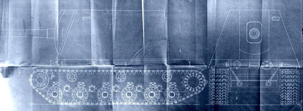
In April 1942, deputy commissar of the Soviet tank Industry, Kotin, commissioned development of a heavy assault gun, factory index U-19, with installation of a 203-mm howitzer on a KV chassis. The howitzer was installed in a casemate with 75 mm frontal armor and 60 mm sides with a removable 30 mm thick roof. For the convenience of loading the howitzer , special equipment was designed, which resembled a similar system used in "Sturmtiger" .
According to the design , the combat weight of the U-19 reached 66 tons, and the height was 3505 mm, which is 5 mm higher than the Maus. The U-19 project entered the Artkom GAU in September 1942 and for a number of reasons was rejected.
At the beginning of 1942, it became clear that one could forget about mastering the production of the KV-3 heavy tank in Chelyabinsk. The plans for the manufacture of heavy assault self-propelled guns "212A" on the basis of the KV-3 were finally given up in April 1942, although the designers did not abandon the idea of a heavy assault self-propelled gun. The KV-7 assault tank was chosen as the base for the new vehicle, the internal space of the wheelhouse of which made it possible to place the 152-mm ML-20 howitzer-gun. The project of a 152-mm self-propelled unit based on the KV-7, indexed U-18, was developed in April 1942 by the UZTM Design Bureau.
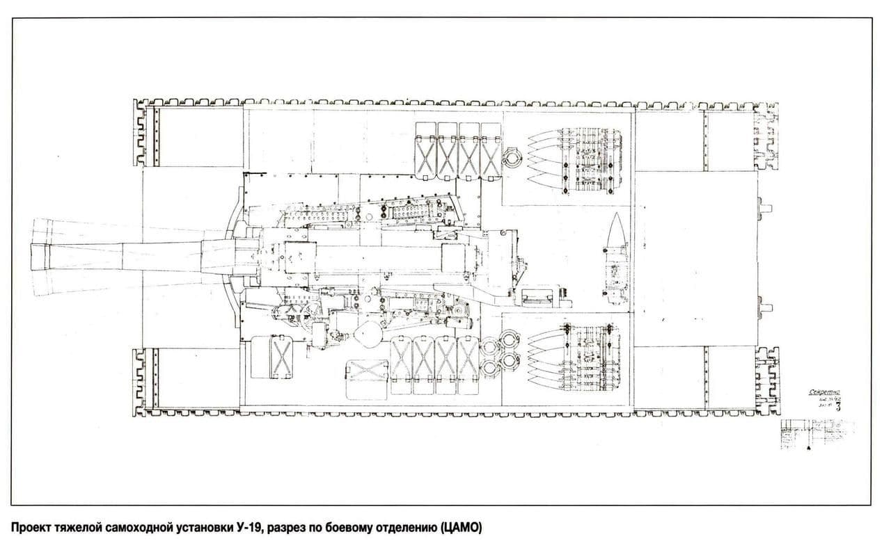
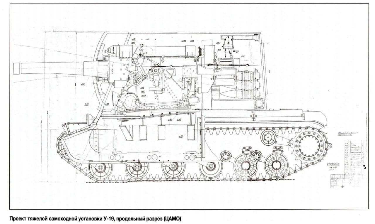
The U-19, unlike the U-18, was not reported at all during reports on the experimental work of the UZTM. It seems that the project was in a lower priority and performed rather as a safety net. Despite this, the team completed the development of the preliminary design of the U-19 earlier than the U-18. The general description of the installation was completed in May, and the drawings in June 1942. The preliminary design of the U-19 went to the GAU and GABTU on August 12, 1942 - 3 weeks earlier than the U-18. The main task of the U-19 developed by the UZTM Design Bureau was the destruction of fortified structures, which were too tough for less powerful systems. Like the KV-7, the base of the KV-1 tank underwent minimal alterations: the turret plate was removed, the engine partition was made removable, the fuel tanks and air intakes were changed. According to the project, the swinging part of the installed 203-mm howitzer B-4, as well as the upper machine, were taken without modification in order to minimize the cost of alteration. A massive casemate was put in place of the turret, completely covering the gun installed in the fighting compartment. At the same time, the casemate partially covered the roof of the engine compartment, which could potentially create difficulties with engine maintenance.
The ambiguous design of the U-19 led to a natural result. On September 9, 1942, the chief engineer of UZTM received a letter signed by the head of the BTU GABTU KA outlining that it would be going no further. It was too heavy, was killing the KV-1 gearbox and was entirely victim to mush of the problems of the KV-2.
The project went to the archive, and only mentions of its existence remained. As a result, this played a cruel joke with the U-19: since all information about the project was limited to the B-4 based on the KV-1, a completely different vehicle was mistakenly recognized for it. In a number of publications, including encyclopedias, as an illustration of the U-19, a project for the installation of a 203-mm U-3 case howitzer in the SU-152 is given. This project has nothing to do with the U-19 at all, even its developer is different - the design bureau of plant No. 9, headed by FF Petrov.
The U-19 really is a Soviet fever-dream. Seriously ugly, totally impracticable and brutally simple. So this is my next project.
Apart from the above pictures, there are very few reference points.
You can find some shots of a very nice 1:35 kitbashed U-19 on : https://maschinenkrueger.com/joomla/...gress&Itemid=6
And there was a very cool 1:35 kitbashed with full interior on https://artmodels.forum2x2.ru/t164-topic.
Otherwise, its thin on the ground.
Mine will be 1:16, no interior, kit bashed, in 100% metal.
My starting point is a Taigen metal lower hull from a KV-1. Because Im am tired of running gears and trying to source bar stock of correct diameters and so on and so forth. So Im going to take all of the Taigen hull, strip it of the plastic bits, replace them with 2 mm steel and reassemble it.
Then buuild the casemate on the top. I think the gearboxes will need some work too given the weight.
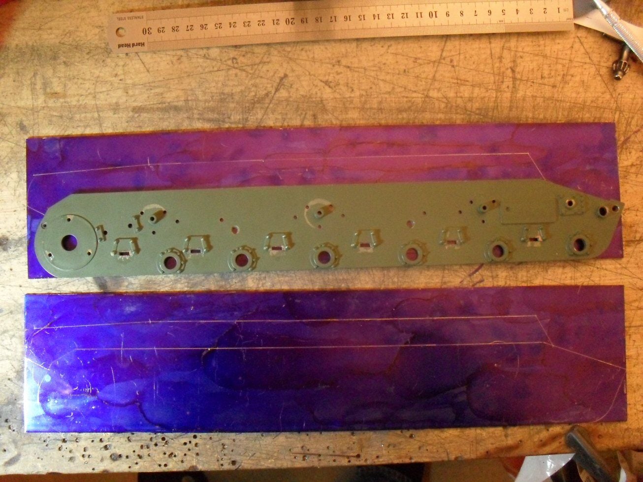
So far I have gotten the hull and taken all the plastic bits off. These being the two side panels. These then serve as templates for creation of the new 2 mm side panels.
These will be a bit different as they are going to stretch up to the engine deck as oposed to ending in the armpits under the fenders.
The templates shoudl let me drill all the holes in the correct places to allow me to reattach all the metal bits to the new sidewalls.
Here is where I am.
Hopefully I can crack on with this fairly quickly. Th ebig problem of course will be the cast gun housing. But I have an idea for that.
P
According to the design , the combat weight of the U-19 reached 66 tons, and the height was 3505 mm, which is 5 mm higher than the Maus. The U-19 project entered the Artkom GAU in September 1942 and for a number of reasons was rejected.
At the beginning of 1942, it became clear that one could forget about mastering the production of the KV-3 heavy tank in Chelyabinsk. The plans for the manufacture of heavy assault self-propelled guns "212A" on the basis of the KV-3 were finally given up in April 1942, although the designers did not abandon the idea of a heavy assault self-propelled gun. The KV-7 assault tank was chosen as the base for the new vehicle, the internal space of the wheelhouse of which made it possible to place the 152-mm ML-20 howitzer-gun. The project of a 152-mm self-propelled unit based on the KV-7, indexed U-18, was developed in April 1942 by the UZTM Design Bureau.
The U-19, unlike the U-18, was not reported at all during reports on the experimental work of the UZTM. It seems that the project was in a lower priority and performed rather as a safety net. Despite this, the team completed the development of the preliminary design of the U-19 earlier than the U-18. The general description of the installation was completed in May, and the drawings in June 1942. The preliminary design of the U-19 went to the GAU and GABTU on August 12, 1942 - 3 weeks earlier than the U-18. The main task of the U-19 developed by the UZTM Design Bureau was the destruction of fortified structures, which were too tough for less powerful systems. Like the KV-7, the base of the KV-1 tank underwent minimal alterations: the turret plate was removed, the engine partition was made removable, the fuel tanks and air intakes were changed. According to the project, the swinging part of the installed 203-mm howitzer B-4, as well as the upper machine, were taken without modification in order to minimize the cost of alteration. A massive casemate was put in place of the turret, completely covering the gun installed in the fighting compartment. At the same time, the casemate partially covered the roof of the engine compartment, which could potentially create difficulties with engine maintenance.
The ambiguous design of the U-19 led to a natural result. On September 9, 1942, the chief engineer of UZTM received a letter signed by the head of the BTU GABTU KA outlining that it would be going no further. It was too heavy, was killing the KV-1 gearbox and was entirely victim to mush of the problems of the KV-2.
The project went to the archive, and only mentions of its existence remained. As a result, this played a cruel joke with the U-19: since all information about the project was limited to the B-4 based on the KV-1, a completely different vehicle was mistakenly recognized for it. In a number of publications, including encyclopedias, as an illustration of the U-19, a project for the installation of a 203-mm U-3 case howitzer in the SU-152 is given. This project has nothing to do with the U-19 at all, even its developer is different - the design bureau of plant No. 9, headed by FF Petrov.
The U-19 really is a Soviet fever-dream. Seriously ugly, totally impracticable and brutally simple. So this is my next project.
Apart from the above pictures, there are very few reference points.
You can find some shots of a very nice 1:35 kitbashed U-19 on : https://maschinenkrueger.com/joomla/...gress&Itemid=6
And there was a very cool 1:35 kitbashed with full interior on https://artmodels.forum2x2.ru/t164-topic.
Otherwise, its thin on the ground.
Mine will be 1:16, no interior, kit bashed, in 100% metal.
My starting point is a Taigen metal lower hull from a KV-1. Because Im am tired of running gears and trying to source bar stock of correct diameters and so on and so forth. So Im going to take all of the Taigen hull, strip it of the plastic bits, replace them with 2 mm steel and reassemble it.
Then buuild the casemate on the top. I think the gearboxes will need some work too given the weight.
So far I have gotten the hull and taken all the plastic bits off. These being the two side panels. These then serve as templates for creation of the new 2 mm side panels.
These will be a bit different as they are going to stretch up to the engine deck as oposed to ending in the armpits under the fenders.
The templates shoudl let me drill all the holes in the correct places to allow me to reattach all the metal bits to the new sidewalls.
Here is where I am.
Hopefully I can crack on with this fairly quickly. Th ebig problem of course will be the cast gun housing. But I have an idea for that.
P

The following users liked this post:
Panther F (02-05-2021)
 01-31-2021, 05:50 PM
#3

Whoa! Will be following this one. 
02-02-2021, 02:57 PM
#4
Wow, nice conversion!!! Will be Hugh!!!
02-05-2021, 04:32 AM
#5
Thread Starter
hello
So I started work on this in earnest and its been a bit up and down.
As siad earlier, I wanted to avoid having to make running gear so I got hold of a metal hull with torsion bars as the base. The plan being to beef it up.
here is the start point.
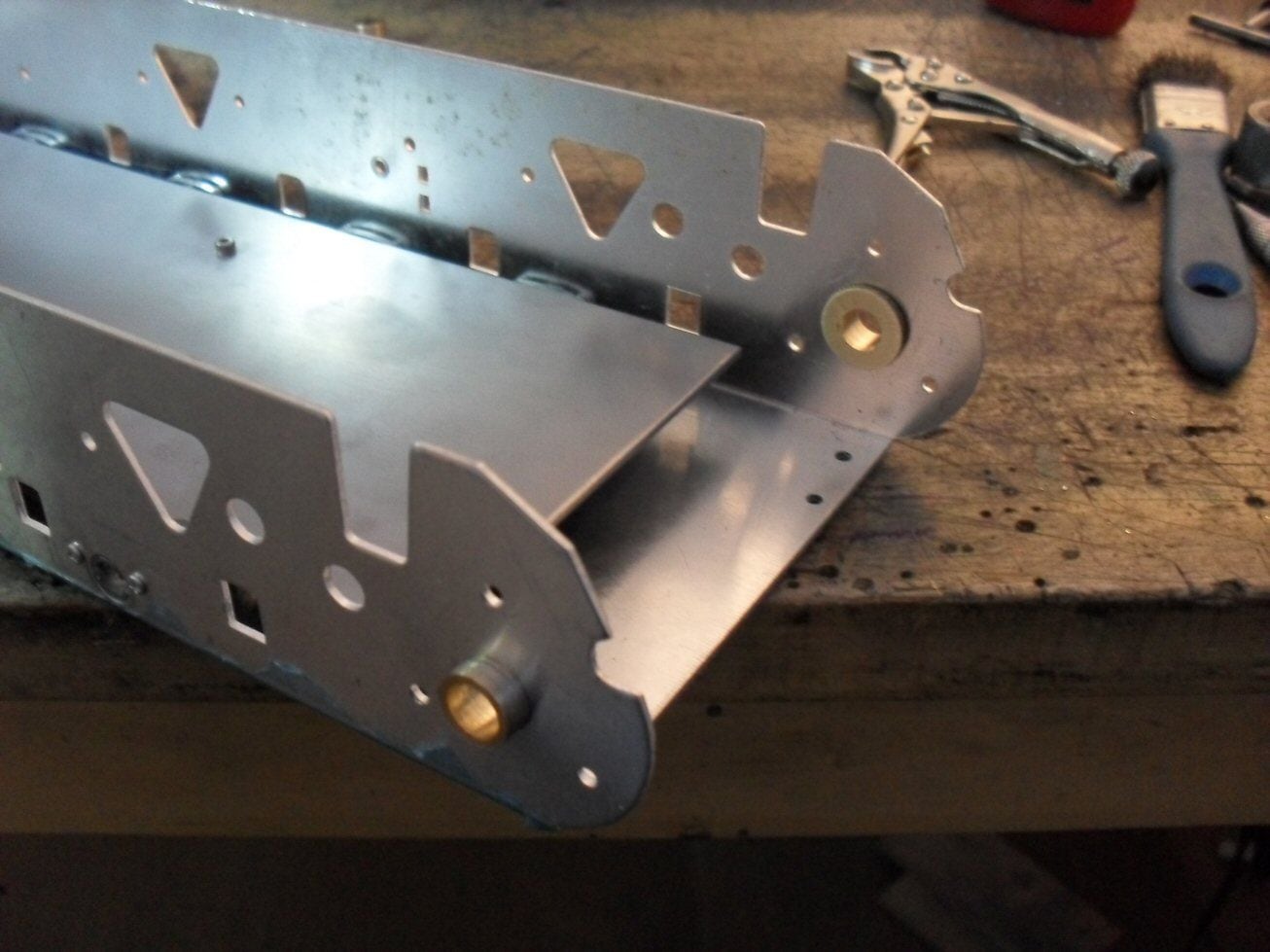
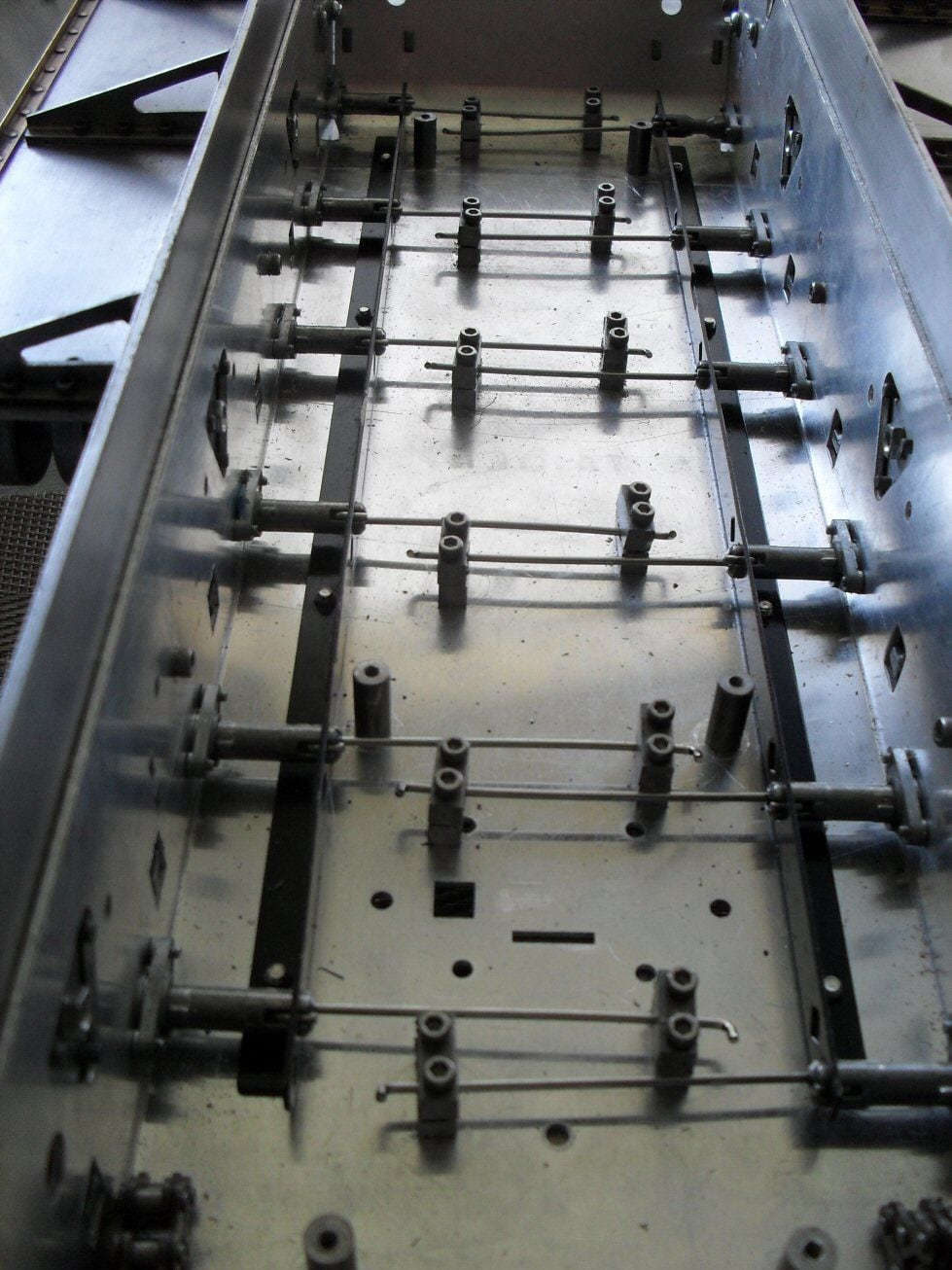
I am not familiar with these things at all. First off I took out everything. It looks like it has taken a smack or two as there are some bends here and there and the front angle iron (that covers the front glacis and lower glacis join) was broken. But RCtank had included a spare so I guess he had spotted that.
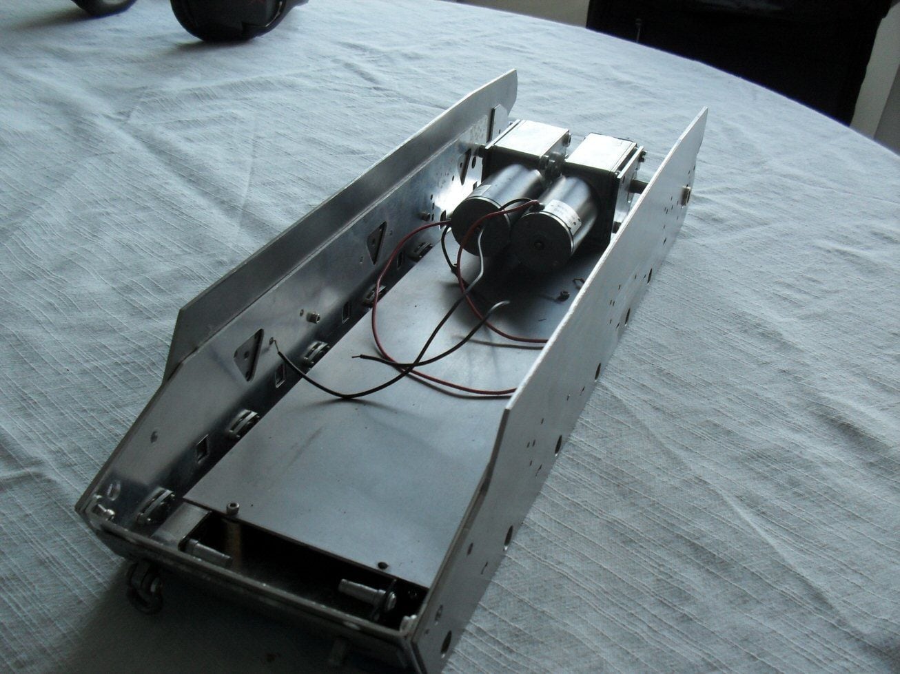
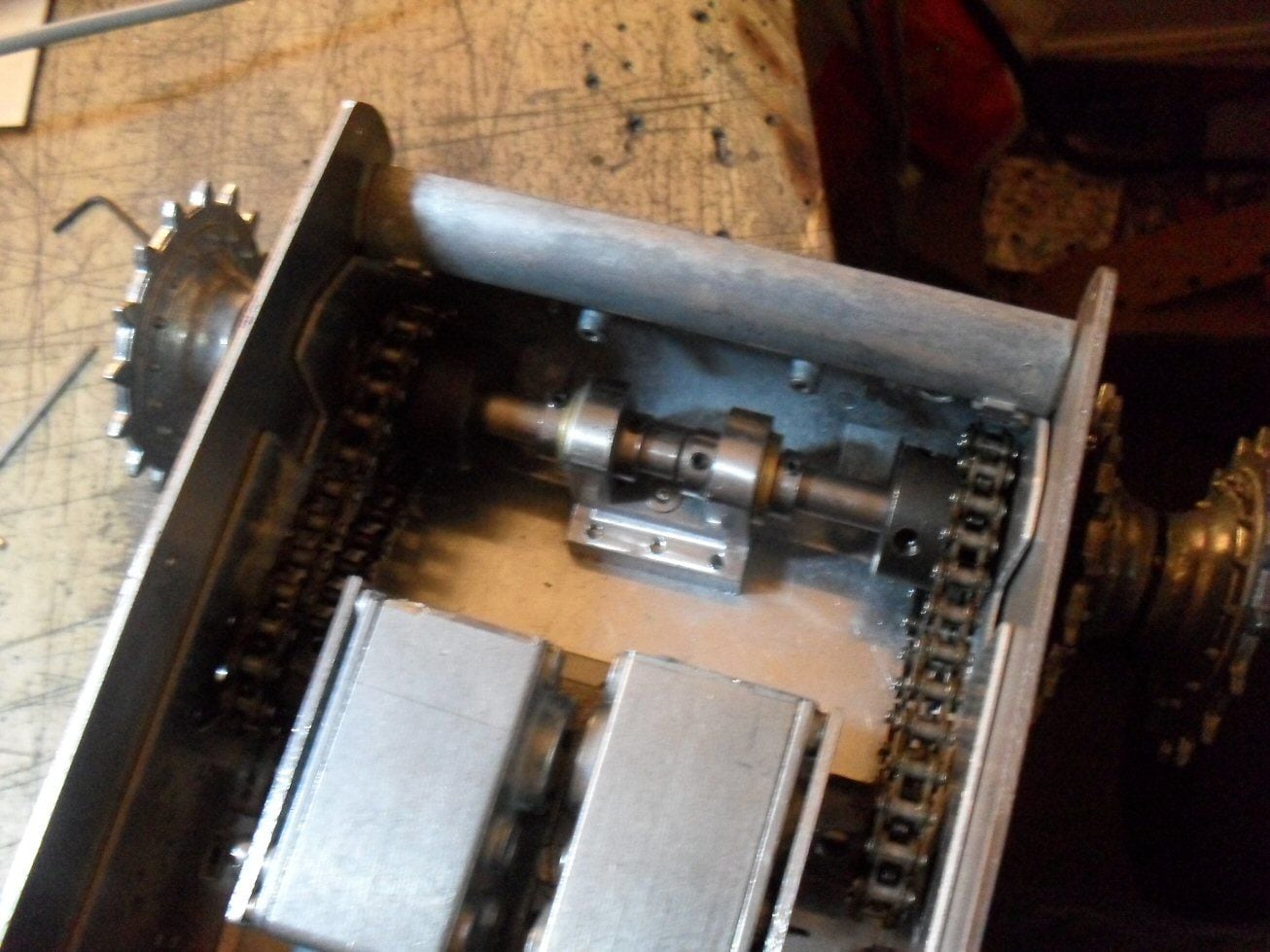
The flimsy mounting deck on teh internal had to go. It was terrible. So I replaced it with a nice piecce of 2mm steel along teh entire hull. Then I stuck in two hefty brass bushings for the rear axle.
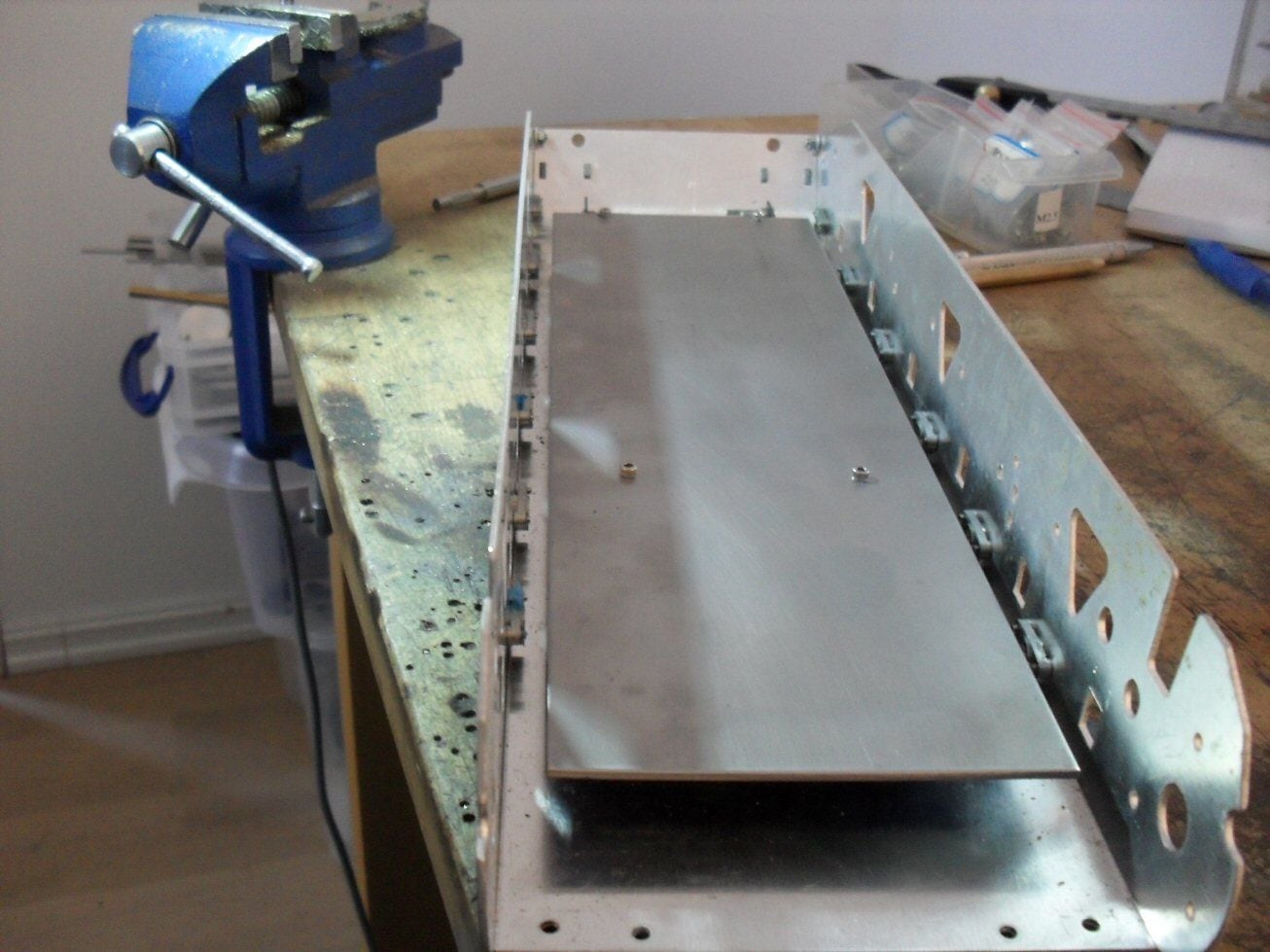
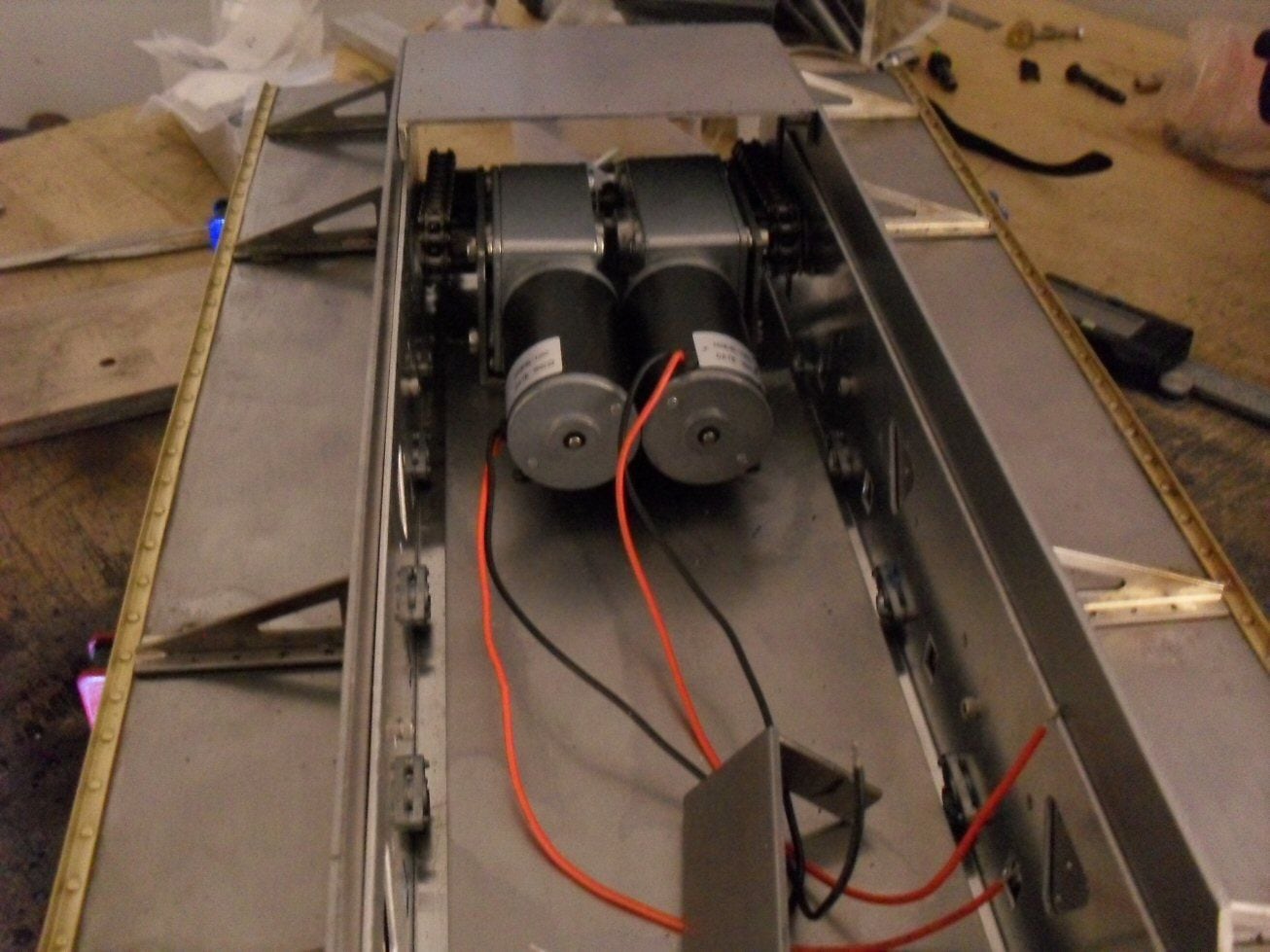
Then I needed a motor mount. Im not using stock gerarboxes although I am doing my best to retain that option by not destroying things that are needed to mount them.
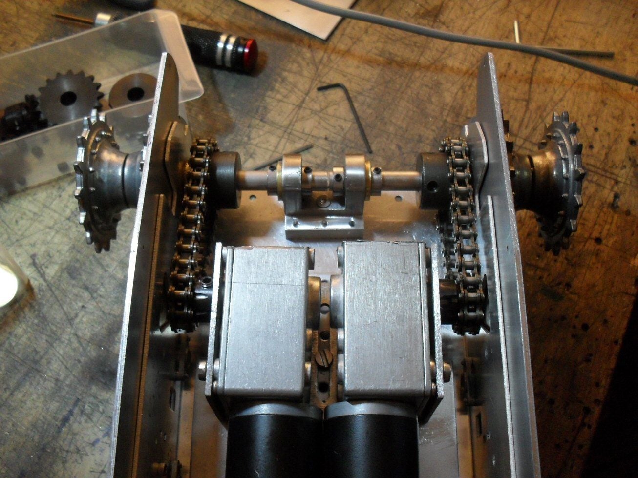
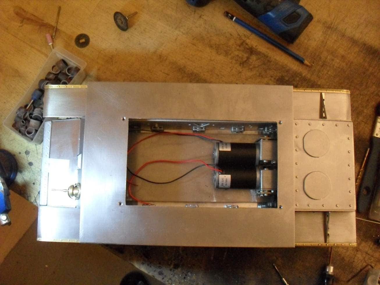
Motor mounts shoudl be machined but thats not an option. The Chinese motiors and gears I bought (Hi torque, low speed!) had drawings so I marked the fixing points on 2 mm steel and fashioned the plates. The housing of the gears needed trimming down for size. Then I brazed the bits together with a brass rod to make the mount.
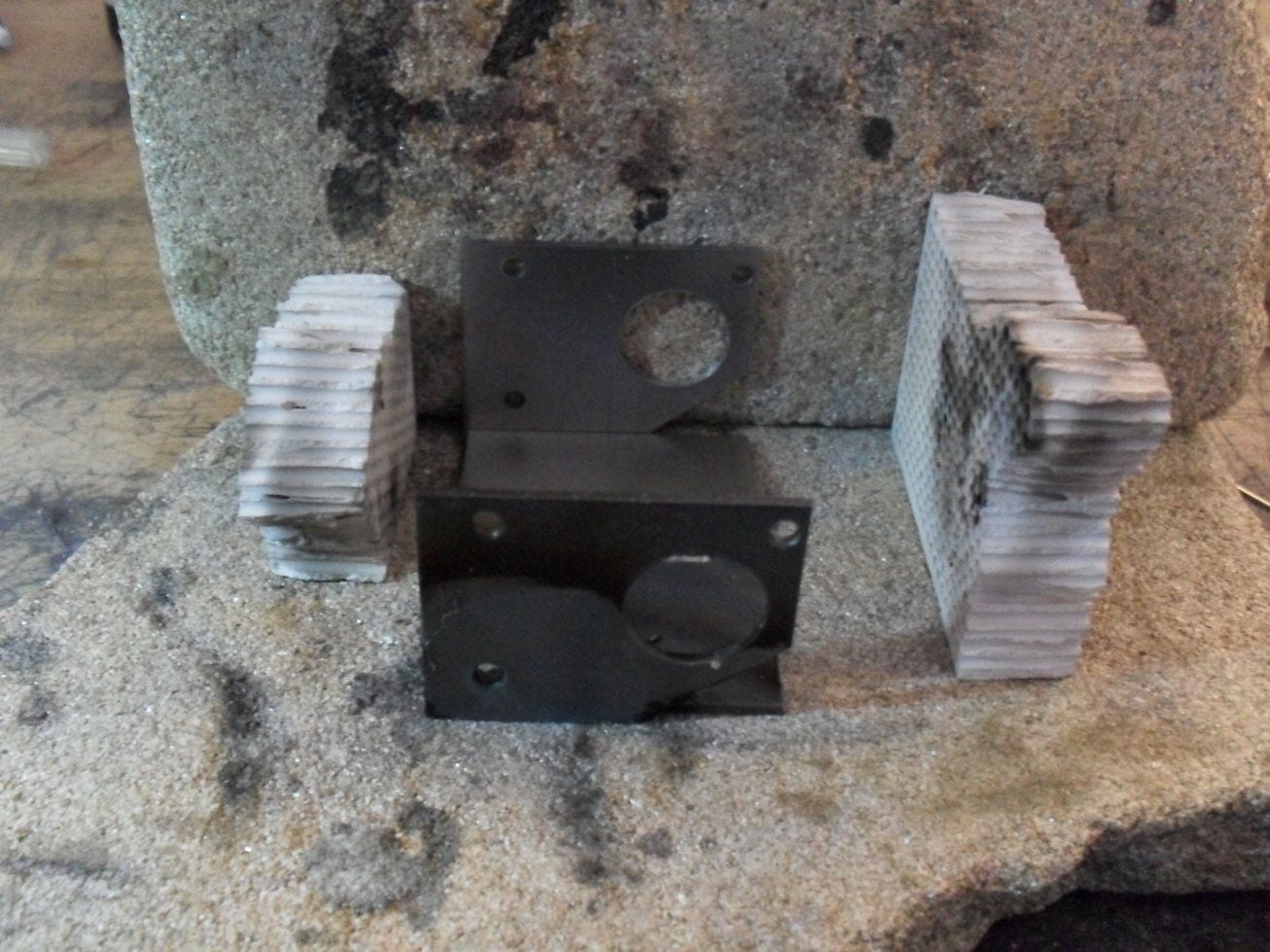
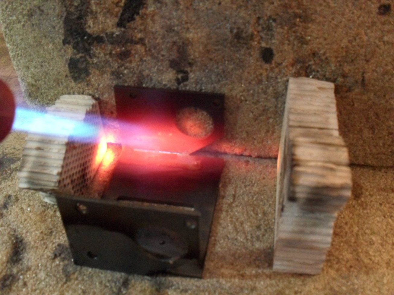
This actually worked out OK and they dont look so bad. Here is a mock up of them in the chassis.
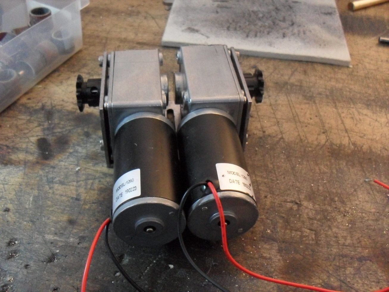
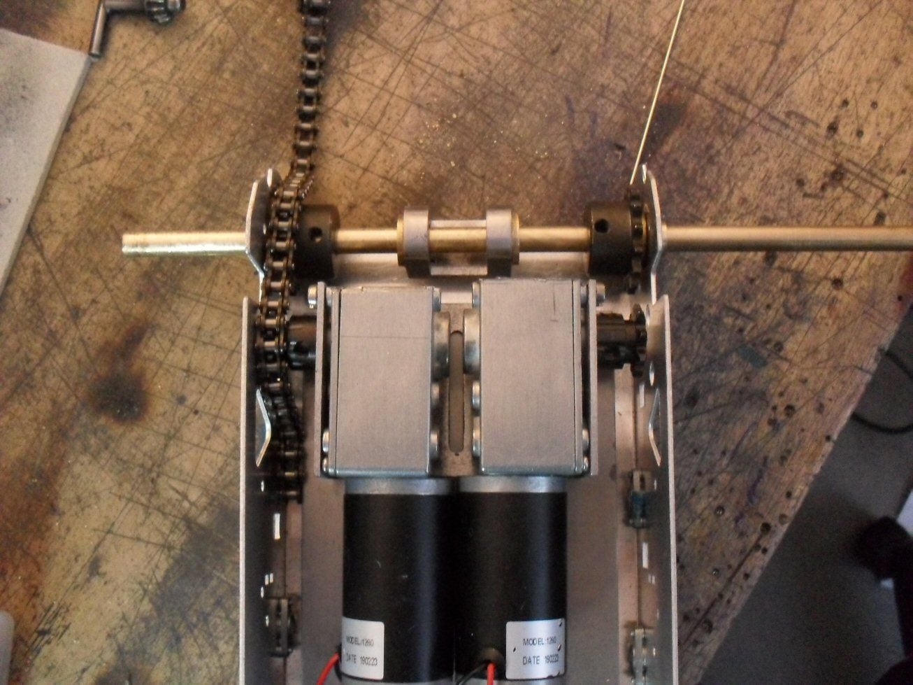
A simple 1/4" pirch chain will go from the gears box to the drive shaft. The axle cog is twice the drive cog so its another step down to reduce speed even more. This tank could not have managed more than about 10 km/hr and I need as much torque as I can to drag its fat ass around as its going to weight a whole lot.
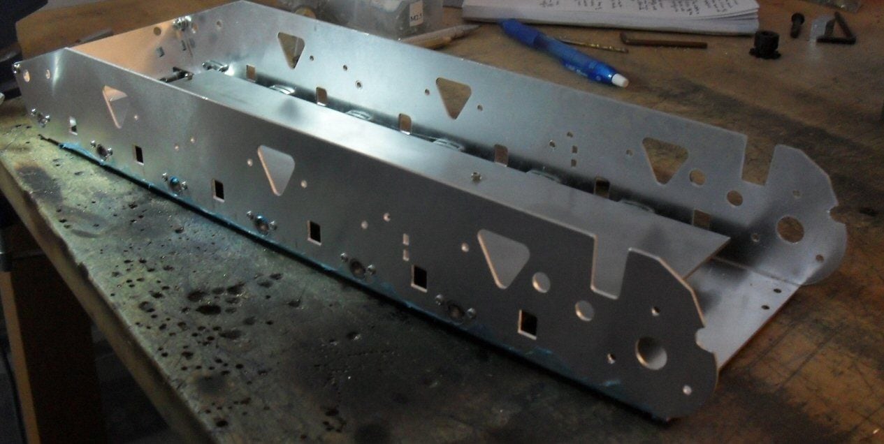
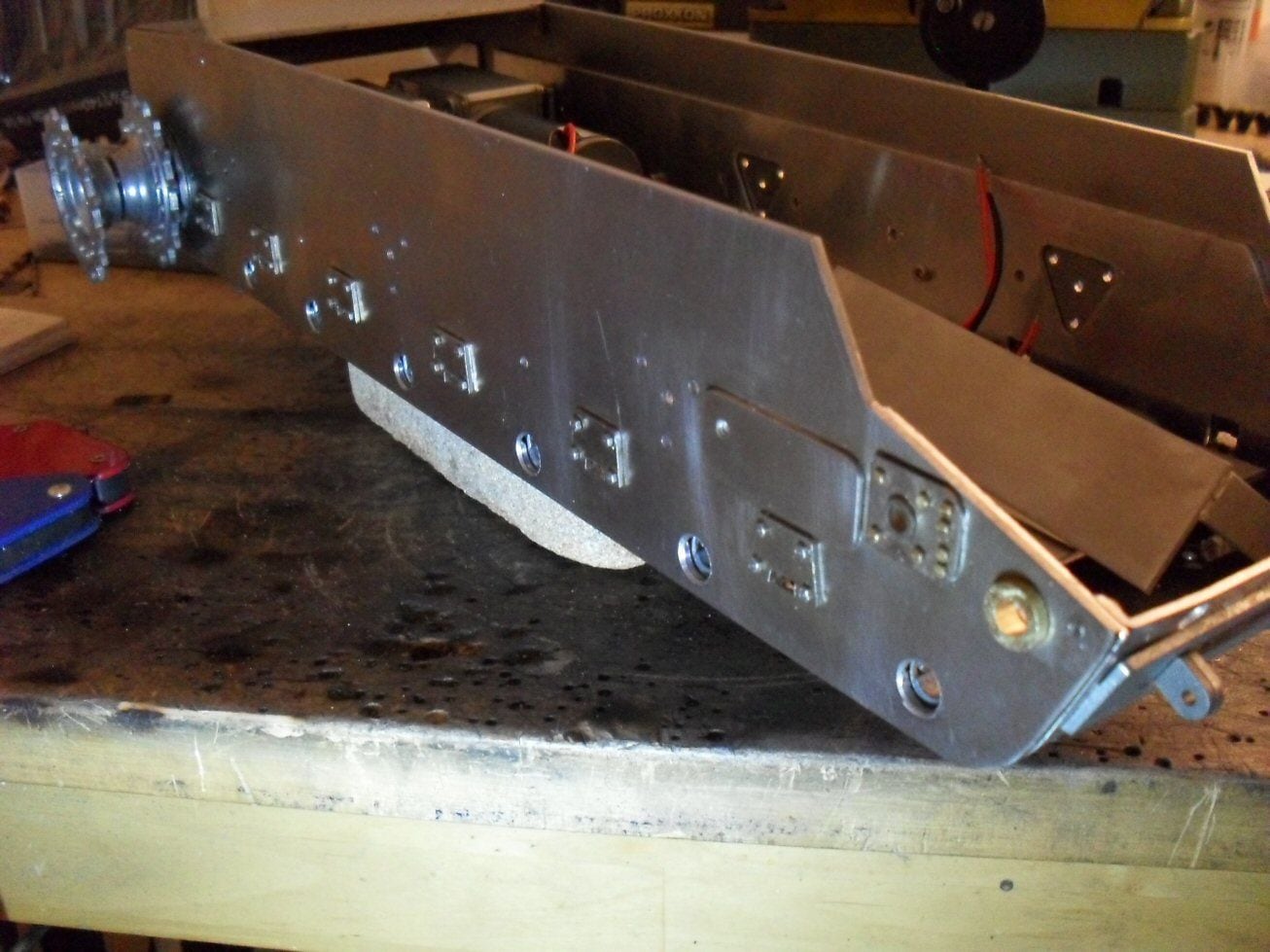
I then took the plastic side bits and used them as templates to drill all the holes required for all the doodah's in the two new side plates.
I dont mind admitting, this fought me all the way.Its like using a banana skin as a template as the plastic is so floppy and weak.
Its not a major problem though as the holes are cosmetic - the moving parts are actually fastened to the aluminium tub so I didnt have to be too exact. But its still a pain in the ass. They sort of line up but a lot of work is needed. And Im going to have try and firm up the aluminium walls (which are now bearing a lot of weight) in relation the aluminium floor or the walls are going to cave in.
I dont know what the mystery metal is that forms the back piece of the tank (its like the stuff duiecast cars are made of) but I have a feeling that drilling it and tapping it is out of the question so thats a problem for the future.
There are also issues like this :
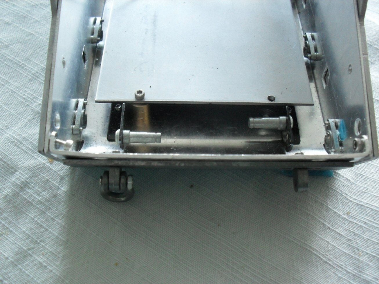
You can see how messed up the front is - its bent I guess. I could possibly put a steel plate in there instead but that means taking a hacksaw to the aluminium tub and it leads to a host of problems down the road.
And the front aluminium panel is really horrible. I could slap a load of JB Weld on it to cover up holes but thats really no great solution.
P
So I started work on this in earnest and its been a bit up and down.
As siad earlier, I wanted to avoid having to make running gear so I got hold of a metal hull with torsion bars as the base. The plan being to beef it up.
here is the start point.
I am not familiar with these things at all. First off I took out everything. It looks like it has taken a smack or two as there are some bends here and there and the front angle iron (that covers the front glacis and lower glacis join) was broken. But RCtank had included a spare so I guess he had spotted that.
The flimsy mounting deck on teh internal had to go. It was terrible. So I replaced it with a nice piecce of 2mm steel along teh entire hull. Then I stuck in two hefty brass bushings for the rear axle.
Then I needed a motor mount. Im not using stock gerarboxes although I am doing my best to retain that option by not destroying things that are needed to mount them.
Motor mounts shoudl be machined but thats not an option. The Chinese motiors and gears I bought (Hi torque, low speed!) had drawings so I marked the fixing points on 2 mm steel and fashioned the plates. The housing of the gears needed trimming down for size. Then I brazed the bits together with a brass rod to make the mount.
This actually worked out OK and they dont look so bad. Here is a mock up of them in the chassis.
A simple 1/4" pirch chain will go from the gears box to the drive shaft. The axle cog is twice the drive cog so its another step down to reduce speed even more. This tank could not have managed more than about 10 km/hr and I need as much torque as I can to drag its fat ass around as its going to weight a whole lot.
I then took the plastic side bits and used them as templates to drill all the holes required for all the doodah's in the two new side plates.
I dont mind admitting, this fought me all the way.Its like using a banana skin as a template as the plastic is so floppy and weak.
Its not a major problem though as the holes are cosmetic - the moving parts are actually fastened to the aluminium tub so I didnt have to be too exact. But its still a pain in the ass. They sort of line up but a lot of work is needed. And Im going to have try and firm up the aluminium walls (which are now bearing a lot of weight) in relation the aluminium floor or the walls are going to cave in.
I dont know what the mystery metal is that forms the back piece of the tank (its like the stuff duiecast cars are made of) but I have a feeling that drilling it and tapping it is out of the question so thats a problem for the future.
There are also issues like this :
You can see how messed up the front is - its bent I guess. I could possibly put a steel plate in there instead but that means taking a hacksaw to the aluminium tub and it leads to a host of problems down the road.
And the front aluminium panel is really horrible. I could slap a load of JB Weld on it to cover up holes but thats really no great solution.
P
The following users liked this post:
herrmill (02-25-2021)
02-05-2021, 05:50 AM
#6
Wow and WOW! Really excited about this one!
(I'm an official member of the 'Fugly Tank Club')
(I'm an official member of the 'Fugly Tank Club')
02-05-2021, 09:10 AM
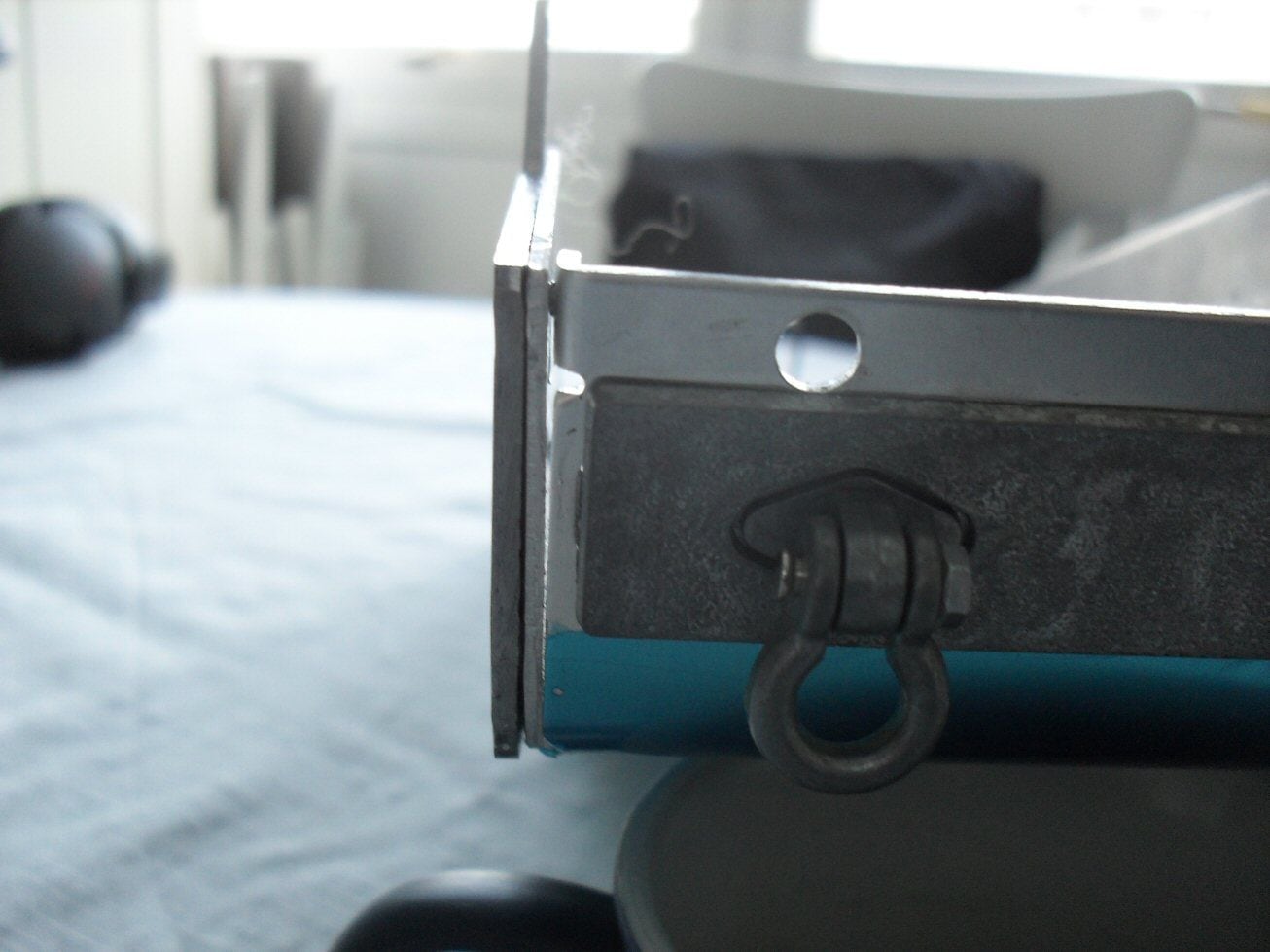
#7
The metal is soft and it can be drilled and tapped, but you have to be really careful with torque of the screws. That add-on armor plate on the front can be removed as I did remove it on my SU-152 build in a Taigen chassis. The front tow hook mounts need to come out for that to happen though. I believe mine were press fit in. After removing them I didn't think glue would be strong enough to hold them. They were loose when I tried to reinstall them so I pinned them in place with some roll pins I had laying around on the inside. I built my 1/6th KV-2 the way you did using the hull sides going all the way up (as it was really built) and added the track side skirts to them.
02-05-2021, 10:02 AM
#8
Thread Starter
The metal is soft and it can be drilled and tapped, but you have to be really careful with torque of the screws. That add-on armor plate on the front can be removed as I did remove it on my SU-152 build in a Taigen chassis. The front tow hook mounts need to come out for that to happen though. I believe mine were press fit in. After removing them I didn't think glue would be strong enough to hold them. They were loose when I tried to reinstall them so I pinned them in place with some roll pins I had laying around on the inside. I built my 1/6th KV-2 the way you did using the hull sides going all the way up (as it was really built) and added the track side skirts to them.
That material is freaking me out and I doubt its easy to get replacements (at least Ive never seen them).
Are the Mato metal tanks made of teh same stuff?
I always thought they looked really sweet but if they are made of this stuff I think I won't bother.
Plastic would be better. More robust at least.
P
02-25-2021, 10:32 AM
#9
Thread Starter
Felt a bit guilty so I am updating this build.
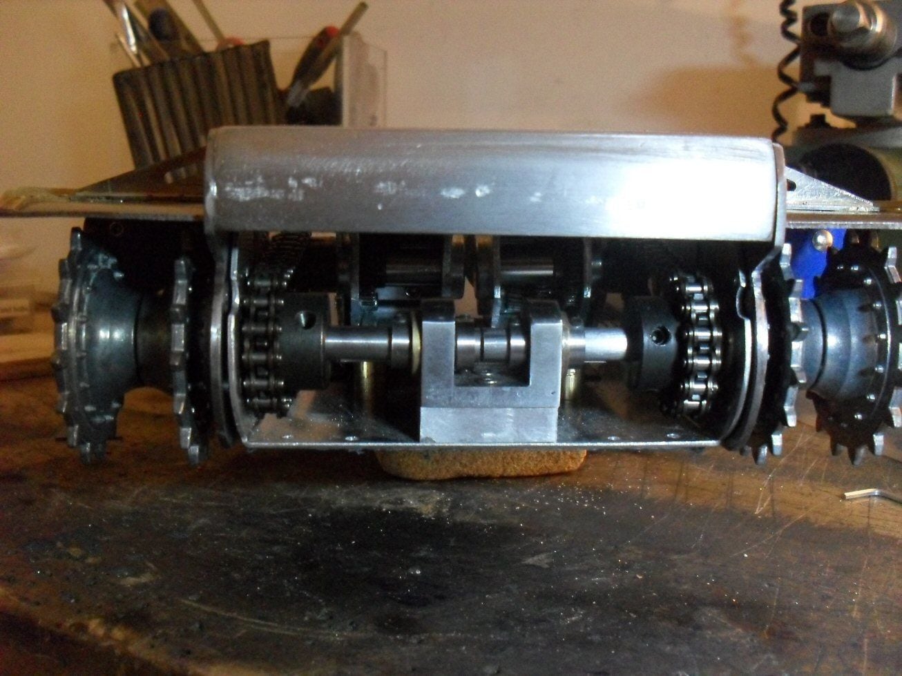
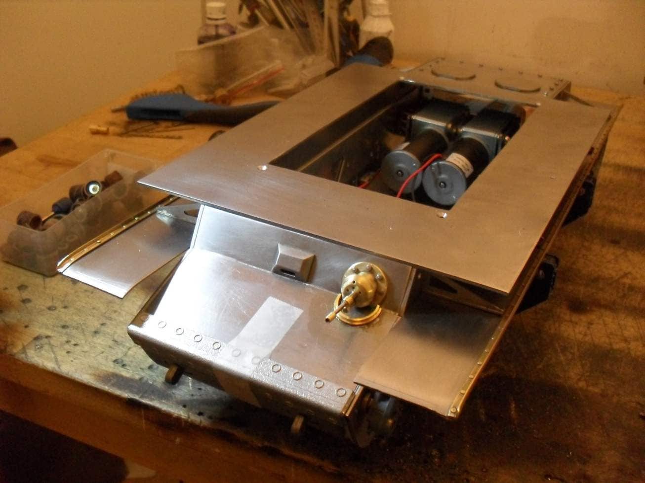
Im 90% finished with the drive system. The drive shafts need some flats and the lengths need adjusting but the motors and drives are done. Fits nicely with the curved bit I am salvaging from the Taigan. Bit of grinding here and there and it will fine.
The rear engine deck is structurally done and works nicely. The main bits of the front glacis are done andjust need fitting.
All the stupid bits down the side of teh hull for the bump stops, the track tensioners etc etc are done. Except the covers around the wheel axles. Im waiting for some steel washers to do those.
The mudguards are 80 % done. I need to bore and tap all the little bolts holding the brackets to the guards but I am going for the version where the brackets are welded to the hull to save some pain.
Once I get the lower hull finished, I can get on to the interesting bit which is the casemate!
Onwards and upwards....
P
The following users liked this post:
herrmill (02-25-2021)
03-11-2021, 09:57 AM
#10
Thread Starter
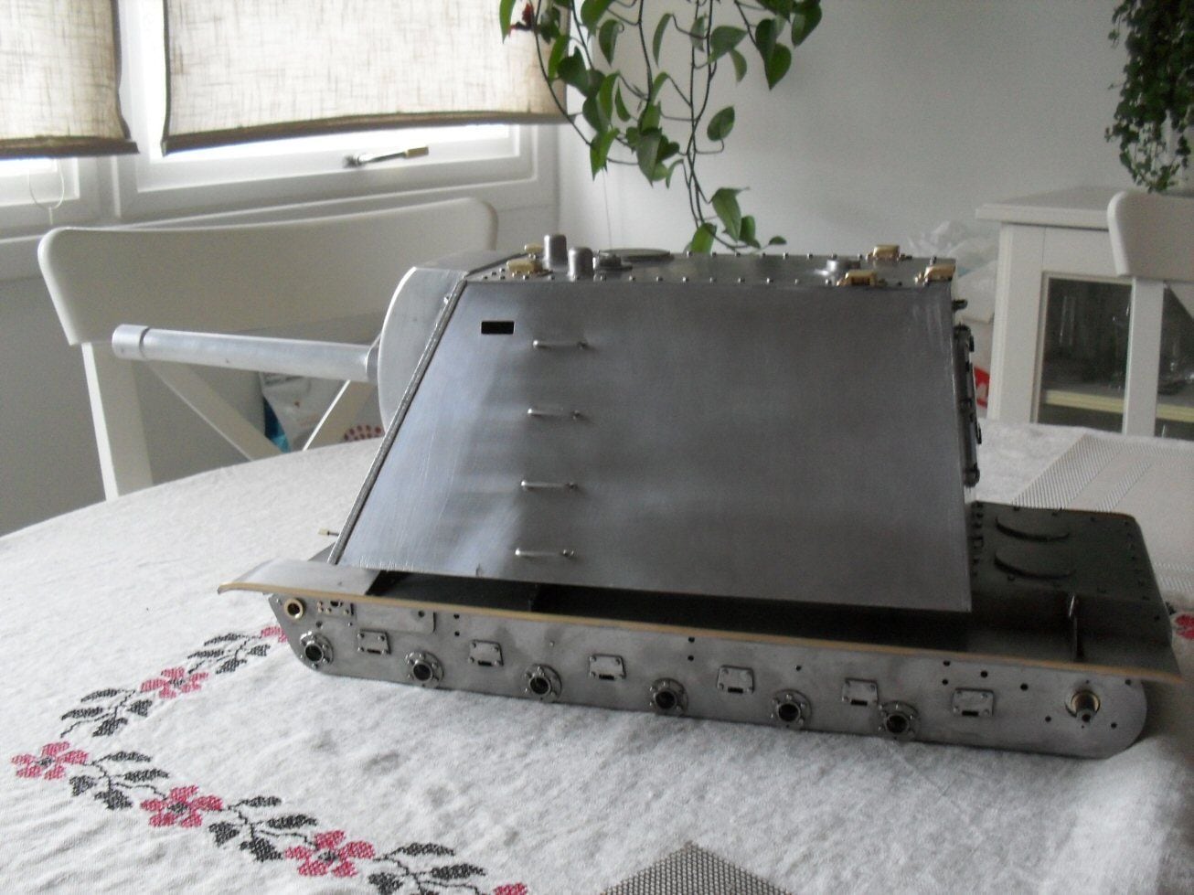
Ive finally started moving from the lower hull to considering the upper part. This stands about 114 mm proud of the engine deck on the lower hull and stretched from teh front glacis to the start of the last section of the engine deck and out over both mudguards.
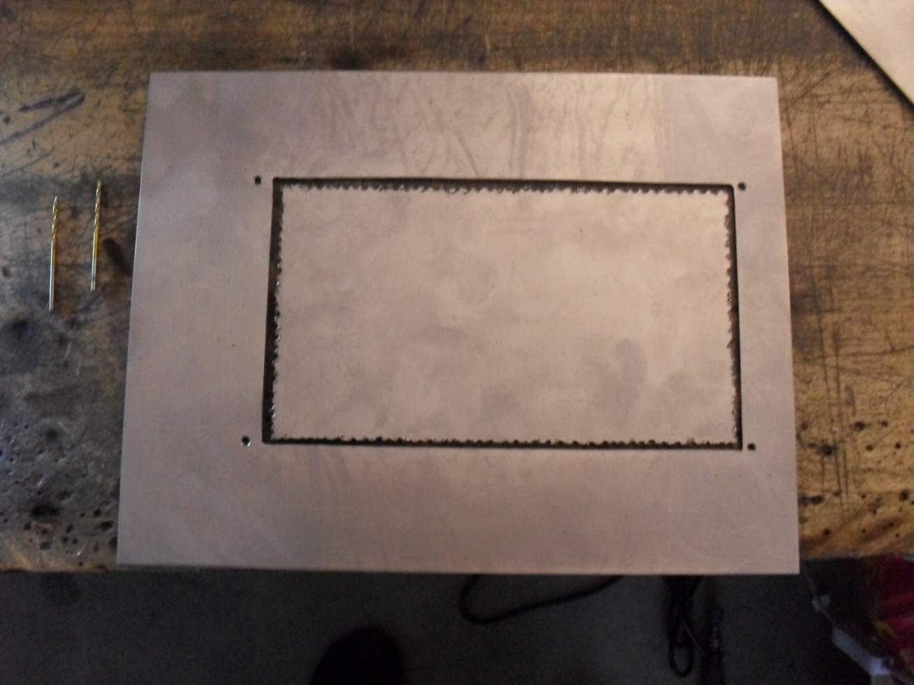
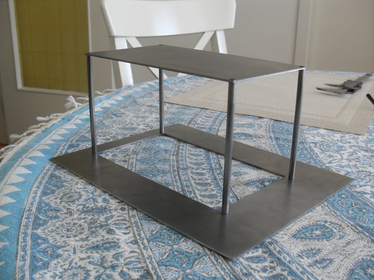
I cut the base plate for teh casemate out of 2 mm steel and got it into shape. Then I chain drilled out the middle bit in a desperate attempt to reduce the weight somewhat. The top piece of the casemate is some 200 mm long and 120 wide and is, repeating myself, 114 mm over the bottom. This will stand on 4, 6 mm silver steel rods (you can see the drill holes for these). Then I will be able to use that structure to hopefully be able to get the measurements I need for the polygonal sides which are all mounted at angles.
I pretty much had to do it this way as the onl;y two measurements I could get off the blueprints with any degree of certainty were the dimensions of the top and bottom plates an dtheir relative positions.
That casemate is probably a similar footprint and volume to a Pz III....all sitting on top of a standard KV-1 chassis. Totally bonkers in a Soviet way.......
Looking at the lower hull, I definitely need to do something with the idler mounts. They will never take the weight. The holes in the hull are brass lined and substantial but the structure of the idler mount itself will not be sufficient. I have to deal with this.
I also need to deal with the springs - they will never take the weight (Im a bit worried about the diecast metal of the swing arms as well and the actual mounts they slide into).
I ordered stronger springs from RCTank and we will see if they are enough.
P
The following users liked this post:
herrmill (04-28-2021)
03-11-2021, 03:32 PM
#11
Wow, great conversion so far!!!
 03-15-2021, 09:56 AM
#14
Thread Starter
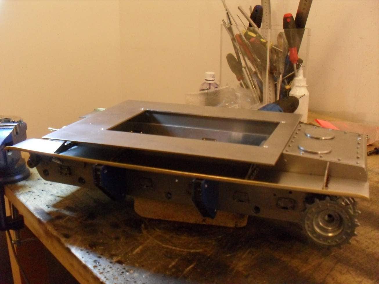
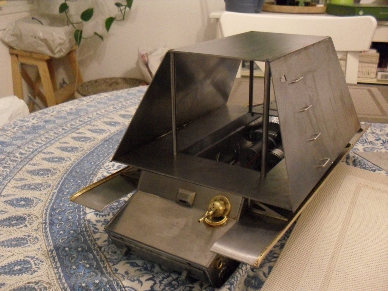
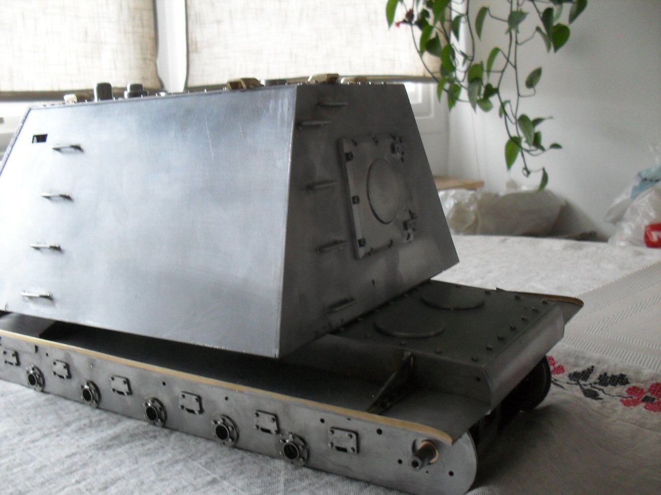
Got my super-structure support for the casemate finished. Pleased with it as it all seems to be straight and true.
Next thing is to clad it with the first three sides - the front armor will have to wait.
Placed on the nearly finished hull (on which I have noticed some nasty mistakes!) really gives an impression of the size.
P
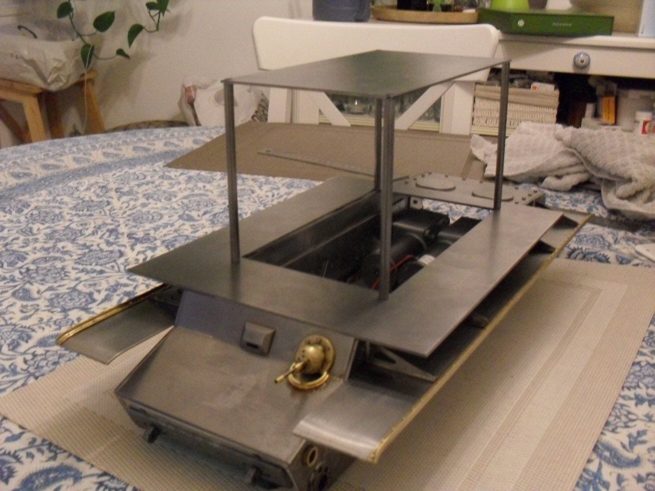
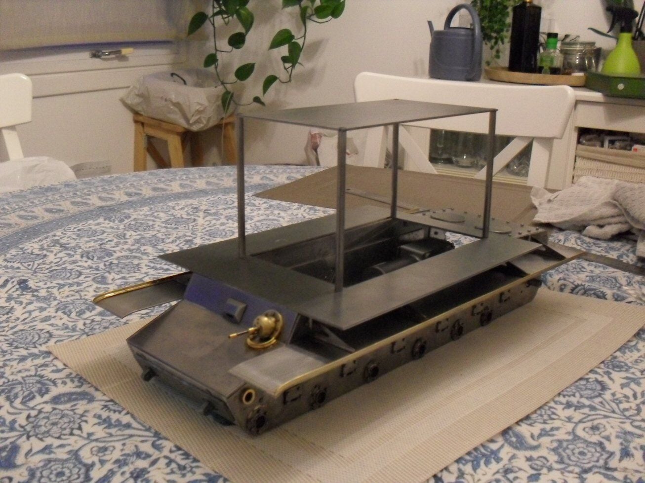
Next thing is to clad it with the first three sides - the front armor will have to wait.
Placed on the nearly finished hull (on which I have noticed some nasty mistakes!) really gives an impression of the size.
P
03-17-2021, 11:16 PM
#15
Thread Starter
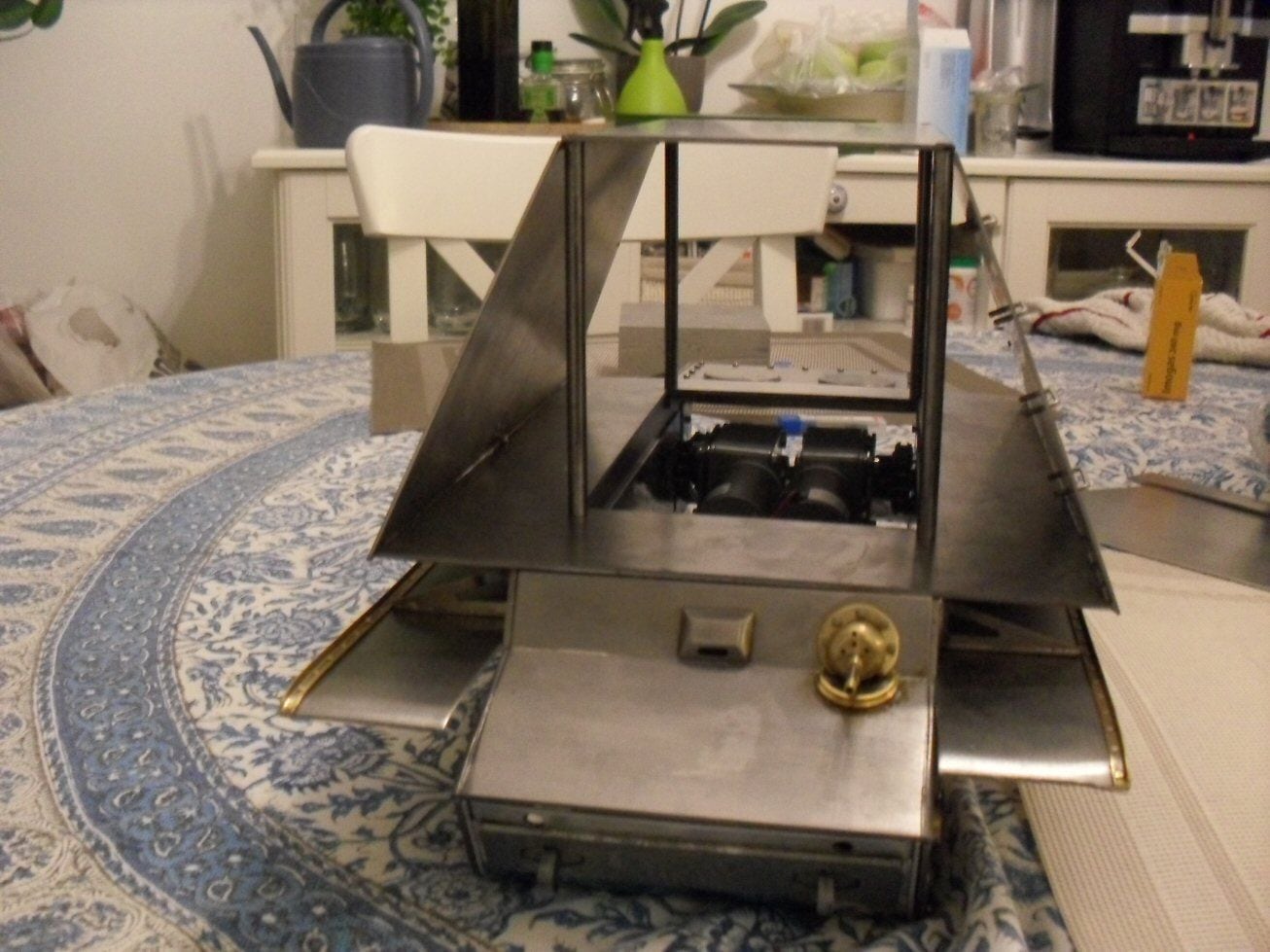
Got started on my casemate today. The two sides had to go on first as they will form the template for the front and back sections.
As I get into it, I am realising that there are vast expanses of bare steel. I may borrow some of the ideas from Russian modellers who supplemented their U-19's with various logical bnits and pieces just to add some visual interest. I have to lokk into that or this is going to look very strange indeed.
P
The following users liked this post:
herrmill (04-28-2021)
03-18-2021, 09:44 AM
#17
It's a cool build and I like odd tanks. I hope it's not so top heavy that it falls over... 
04-28-2021, 09:57 AM
#18
Thread Starter
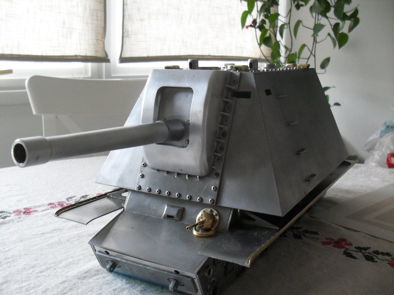
Ive been a bit quiet on this build but have actually been busy. The main issue was this mantlet. Its a massive chunk of aluminium. Cutting out the shape and all the filing took about 2 hours a night for three weeks. And it still isnt exactly right! But it will have to do.
All the doodahs on the roof are placed based on a conglomeration (3 actually) of what earlier modellers have done as there is no real information as to what went where. I will also be borrowing some ideas from these modellers to add some visual interest.
The casemate is still not done but is nearer finished that not. Its a bit of a dogs breakfast at the minute but for once .... I am not spendinghours cleaning and polishing. It can stay rough and I will be painting it I reckon as I hate trying to clean these models.
It really is a strange looking thing but I guess thats one of the reasons it was never built!
Otherwise its just a matter of plugging on at it.
Anyone know where I can get some nice metal KV tow cables? I dont like the looks of the ones on rctank.de for some reason (the eyelets look wrong?).
P
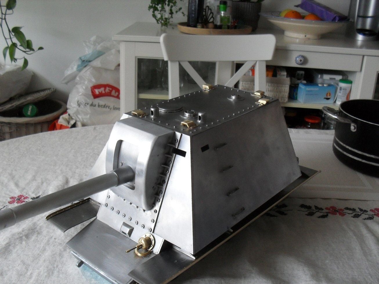
The following users liked this post:
herrmill (04-28-2021)
04-28-2021, 02:57 PM
#19
Soviet tanks of WW2 used several different types of tow cables depending on the weight of the vehicle. T-34 cables have smaller ends on them than the cables used for the KV series. My KV book shows two types that are both represented by these 1/35 scale versions for reference:
Eureka XXL 3508 Towing Cable for KV-1/KV-2 Early Type (set of 2) Eureka XXL ? Model Accessories � ER-3508 Towing cable for KV-1/2 (Early) Tanks
Eureka XXL 3509 Towing Cable for KV-1/KV-2 Late Type (set of 2) Eureka XXL ? Model Accessories � ER-3509 Towing cable for KV-1/2 (Late) Tanks
Eureka XXL 3508 Towing Cable for KV-1/KV-2 Early Type (set of 2) Eureka XXL ? Model Accessories � ER-3508 Towing cable for KV-1/2 (Early) Tanks
Eureka XXL 3509 Towing Cable for KV-1/KV-2 Late Type (set of 2) Eureka XXL ? Model Accessories � ER-3509 Towing cable for KV-1/2 (Late) Tanks
04-28-2021, 09:09 PM
#20
Thread Starter
Its the bottom ones I was after in metal with no success.
the ones I was thinking about are these:
https://www.rctank.de/IS-2-KV-1-Flex...pcs-each-23-cm
but they look like cables from rc crawlers or something. Even the turnbuckle - if thats what it is - looks terrible.
p
the ones I was thinking about are these:
https://www.rctank.de/IS-2-KV-1-Flex...pcs-each-23-cm
but they look like cables from rc crawlers or something. Even the turnbuckle - if thats what it is - looks terrible.
p
05-20-2021, 09:36 AM
#21
Thread Starter
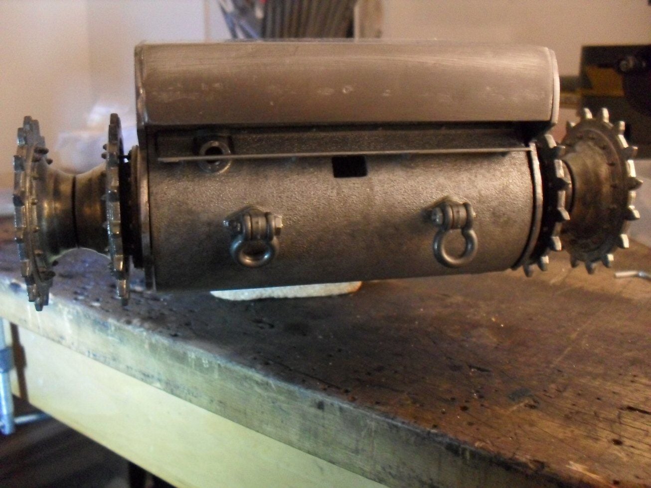
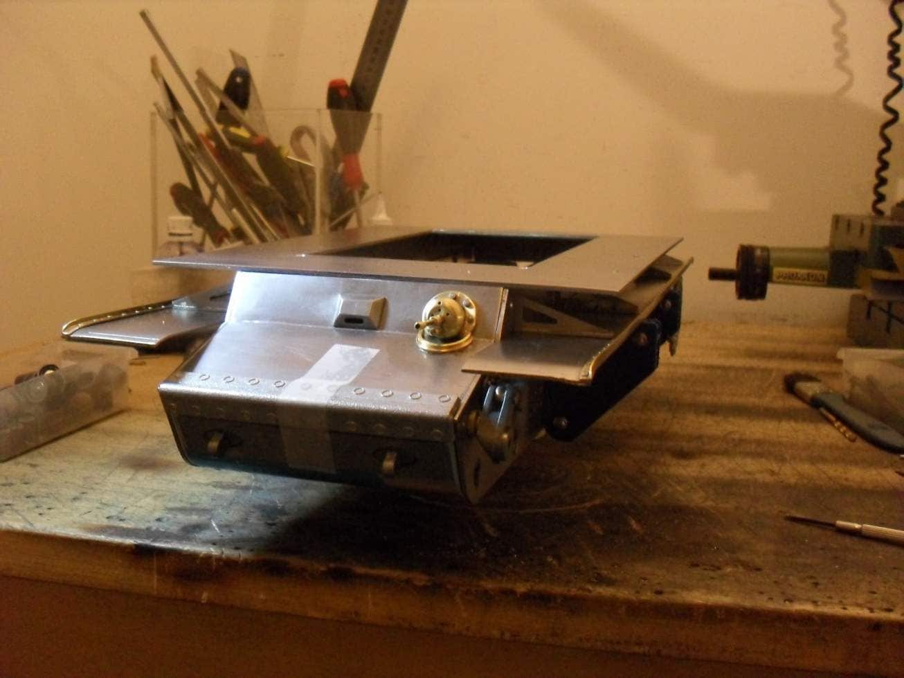
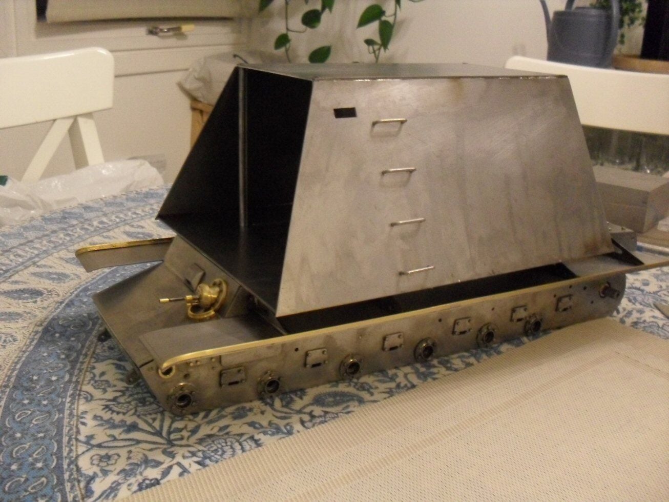
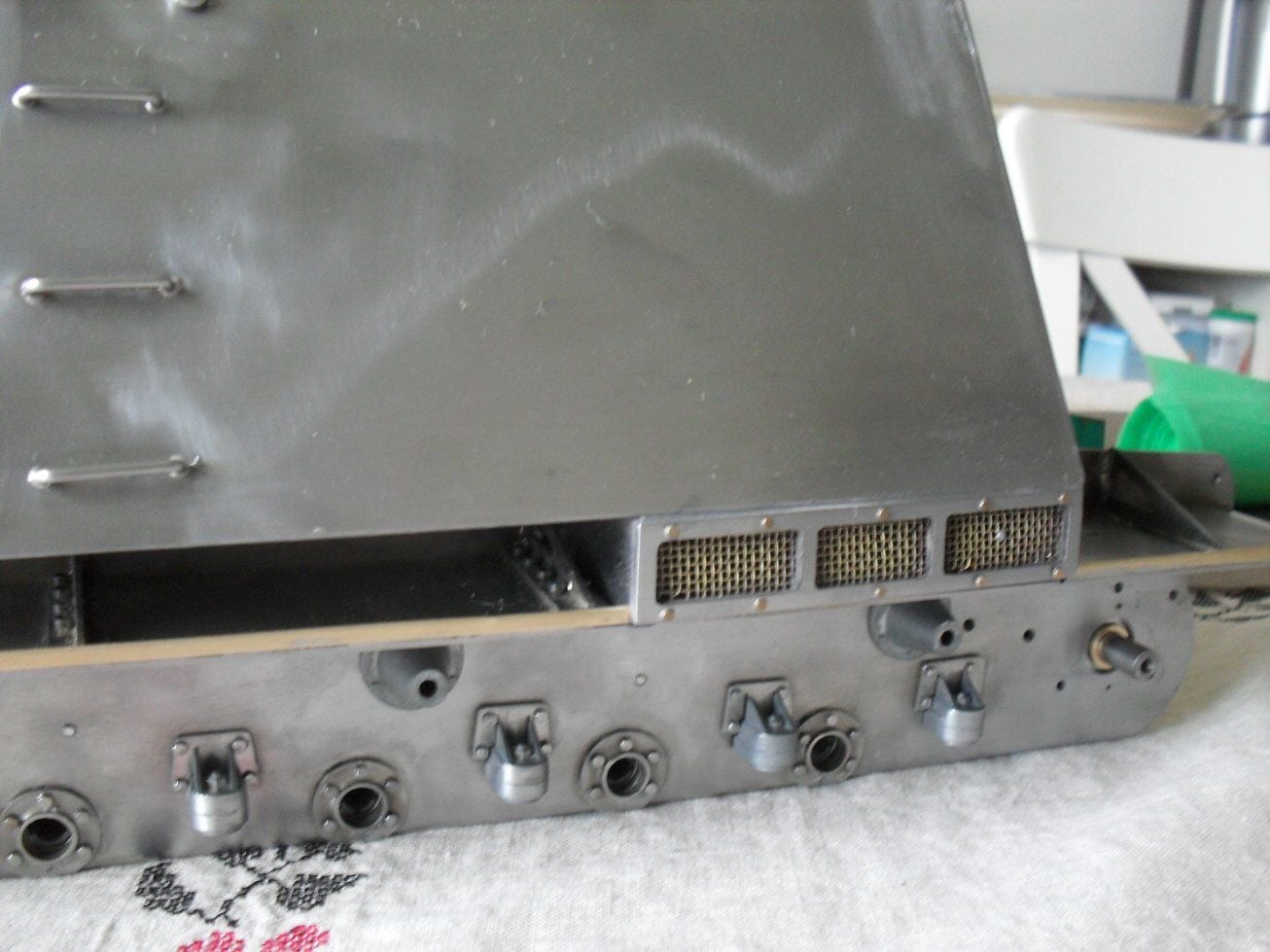
Had to deal with the modified KV1 airfilters. I spent a bit of time measuring the pictures I had and checking some angles and spenta few days fabricating two of them. I mounted them and as can be seen in the picture below, they looked like complete a&se and nothing like what I see on other models.
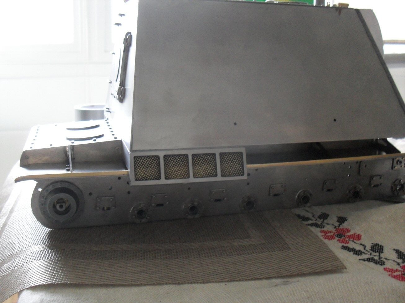
The ones above extend beyond teh mudguards and follow the same slope as the hull. BUt look horrible. So off they came and a new set was made, this time being vertical on teh face and not extending past the mudguards. This meant modifying the lip that runs the length of the mudguard and which I spent a tedious few hours applying months ago. But they look much better to my mind.
I also went at the front end of the mudguards as I need these to be complete before I can finish off the front glacis which is holding up progress. A couple of bits of copper filled in teh curve under the front and now I can proceed with the rest of the front.
P
05-21-2021, 06:19 AM
#23
Once again: Outstanding work, artistry really. Your working is simply outstanding. First class.
Your construction articles are a virtual Master Class on scratch building in metal..
Jerry
Your construction articles are a virtual Master Class on scratch building in metal..
Jerry
05-21-2021, 03:17 PM
#24
If I only had some of your ability to work metal??? Wow!!!
06-08-2021, 09:07 AM
#25
Thread Starter
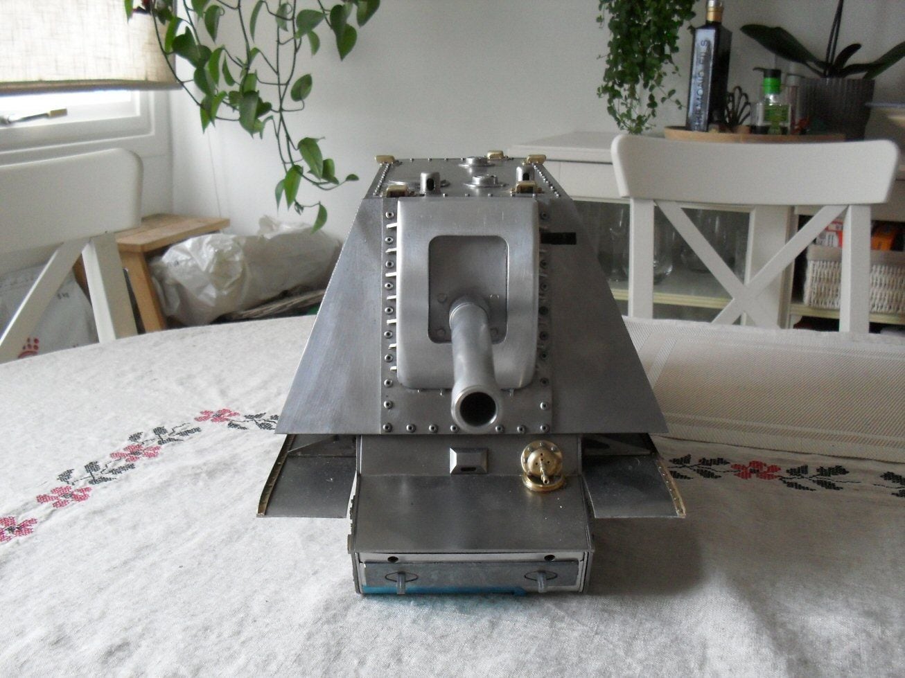
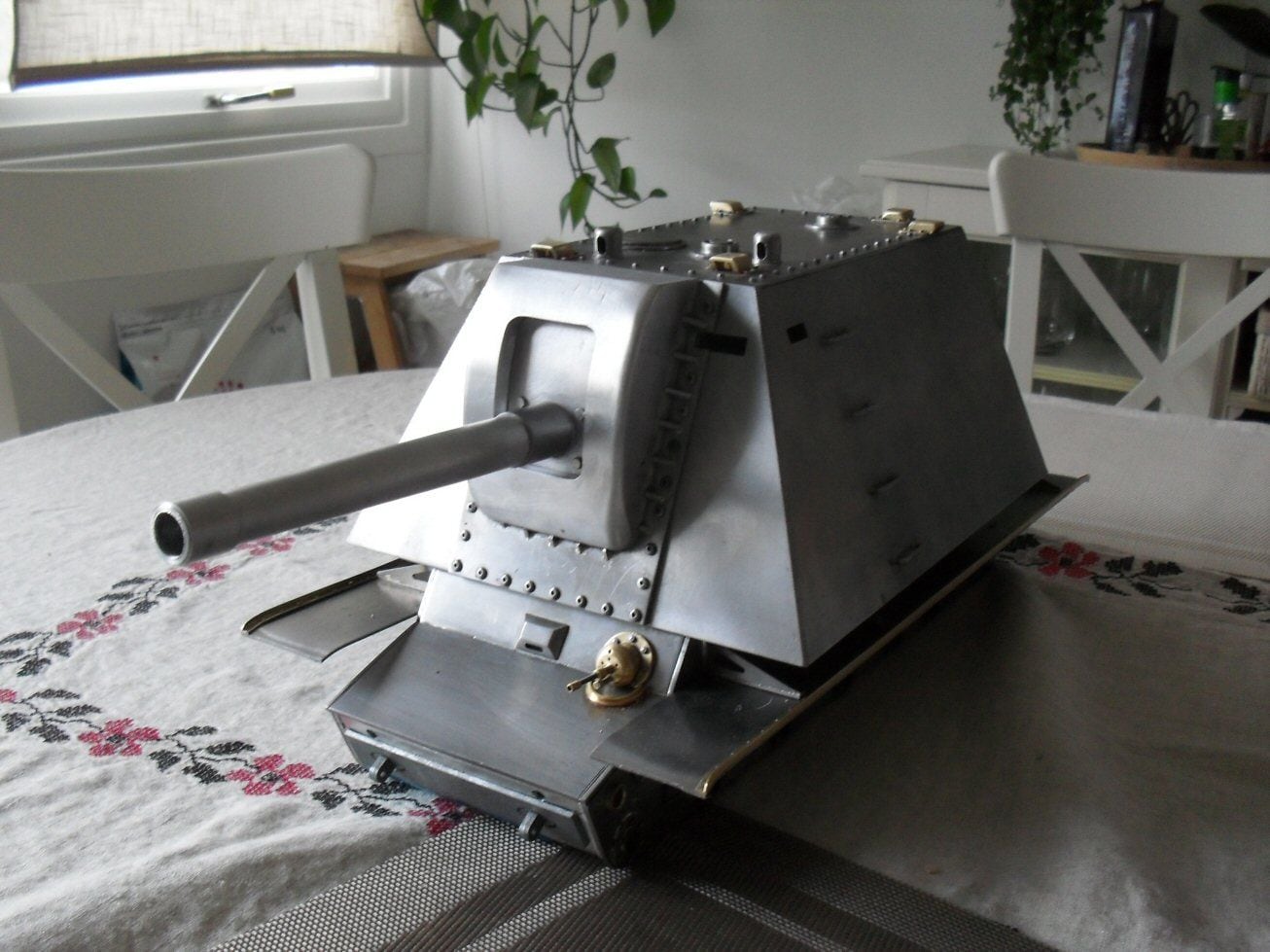
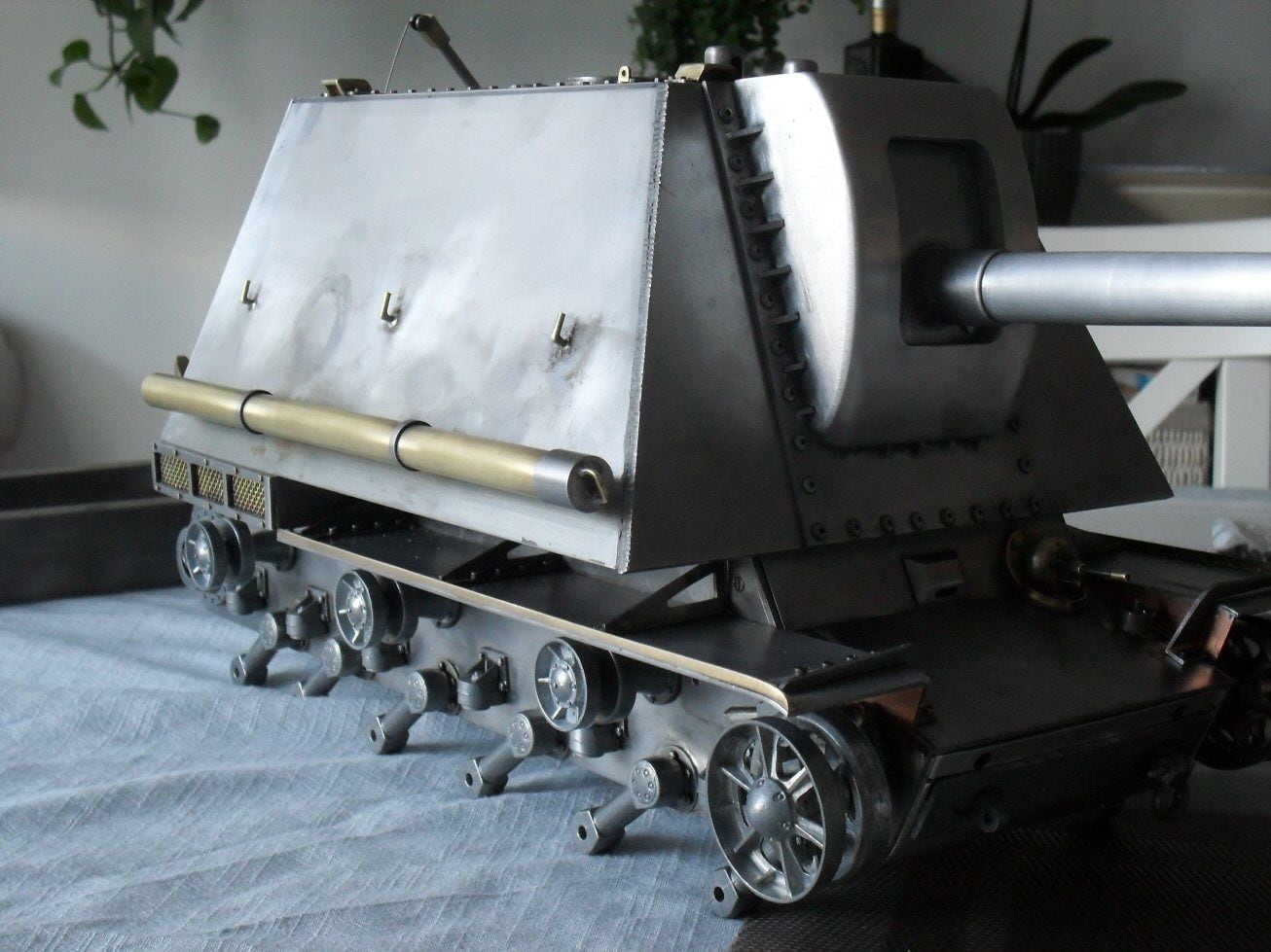
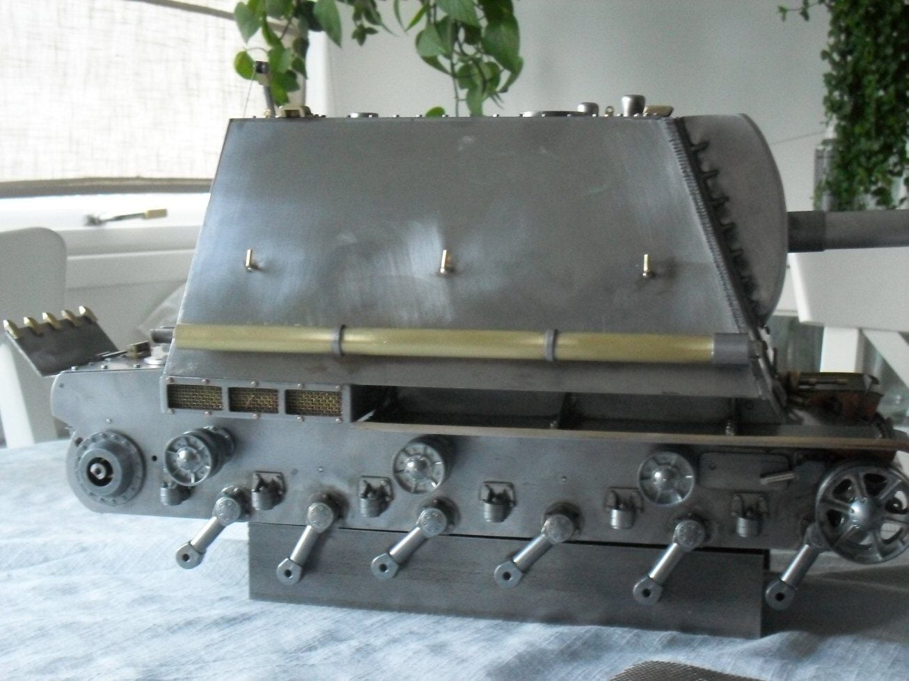
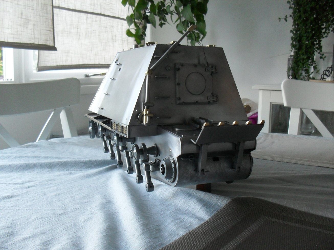
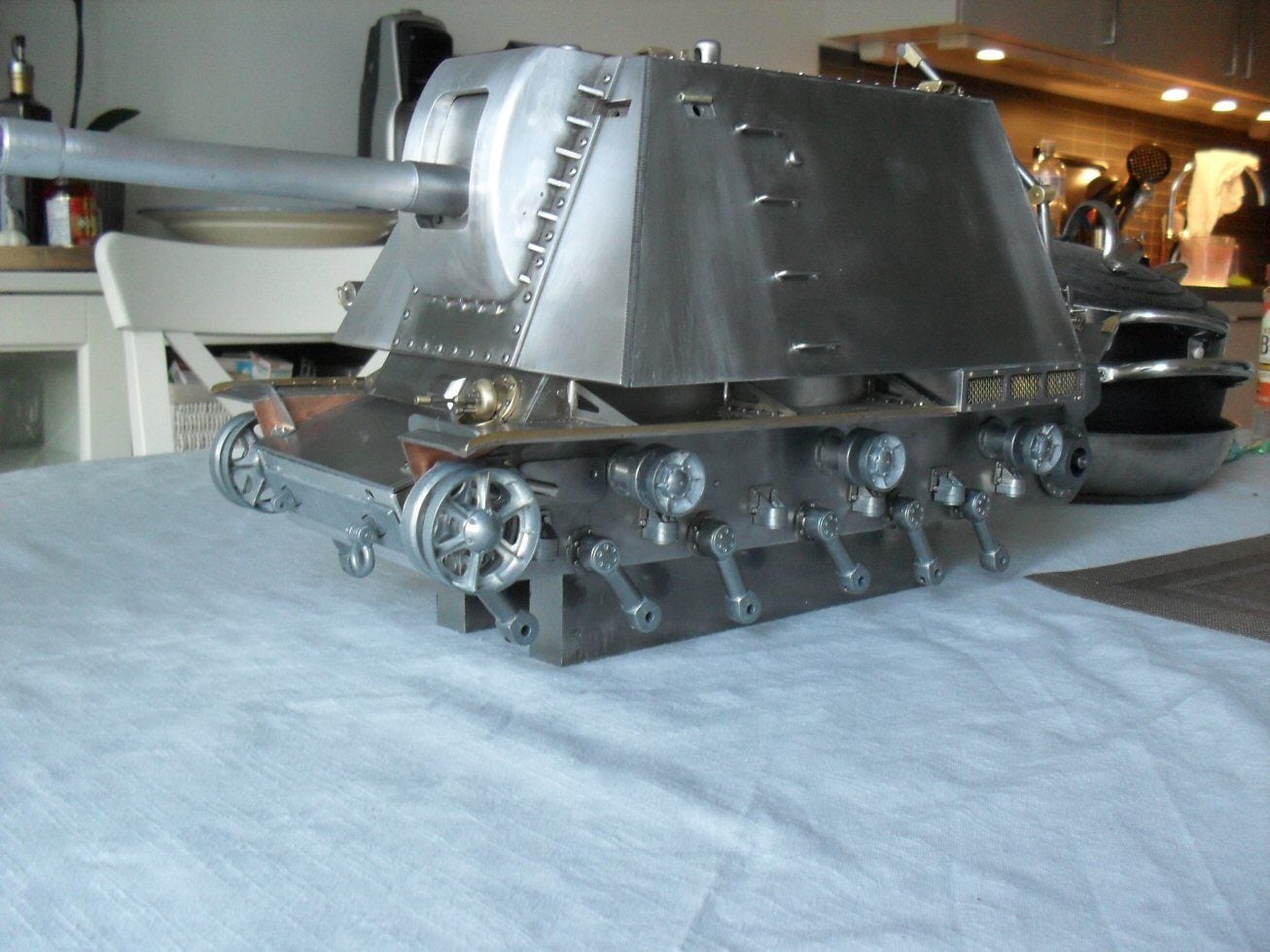
Thought I would update this.
Bear in mind - lots to do, needs sanding and cleaning, will be p ainted, temporary fixings.
I had to rejig the suspension to allow for the excessive weight and to make adjustments. BUt it supports the weight now and Im happy. I can tweak it later if I have to.
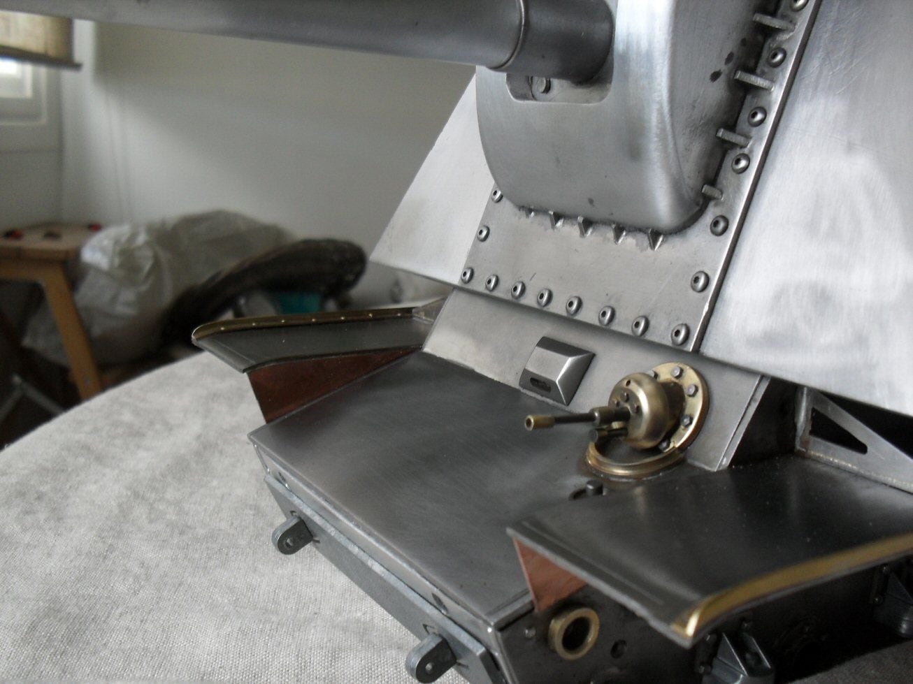
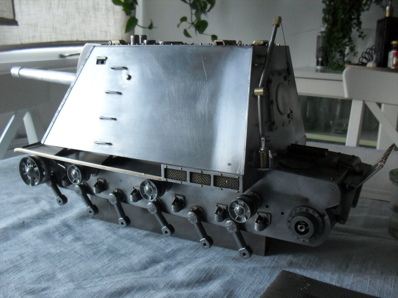
I really like what some russian modellers did with their U-19s to facilitate loading of the huge sheels and to counteract the recoil. So I did the same (shamelessly copying if not inspried by).
The rear mufguard sections were driving me nuts to get them right but then I noticed some other modellers had eliminated them so off they came.
Everything thats left is the stuff Ive been avoiding.
Truth be told Im at that point where this is becoming a bit of a slog but I'll get there in the end.
P
Bear in mind - lots to do, needs sanding and cleaning, will be p ainted, temporary fixings.
I had to rejig the suspension to allow for the excessive weight and to make adjustments. BUt it supports the weight now and Im happy. I can tweak it later if I have to.
I really like what some russian modellers did with their U-19s to facilitate loading of the huge sheels and to counteract the recoil. So I did the same (shamelessly copying if not inspried by).
The rear mufguard sections were driving me nuts to get them right but then I noticed some other modellers had eliminated them so off they came.
Everything thats left is the stuff Ive been avoiding.
Truth be told Im at that point where this is becoming a bit of a slog but I'll get there in the end.
P