


125% (1/4 scale) Anderson TA-152H


 09-09-2014, 09:09 PM
#52


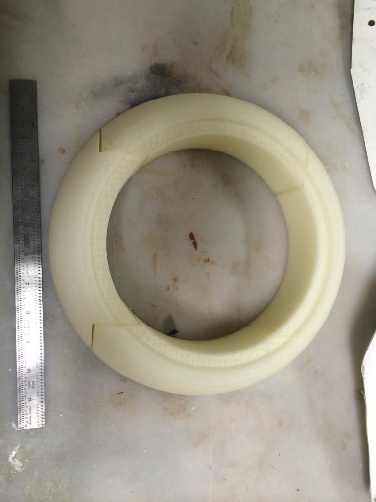
The entire cowl ring has been printed.. I need to get off my butt and finish some pancakes now so i can start gluing wood together. I am Really looking forward to getting started bashing balsa on this thing, it should be a nice relaxing build... Ooh, im still waiting on wing tubes for this thing as well... Apparently the postal service lost the last order as i am at week 5 since those were ordered.

 11-28-2014, 06:16 PM
#55
To windy and chilly to paint today, so after helping a friend out, i got started on some more Ta152 stuff.
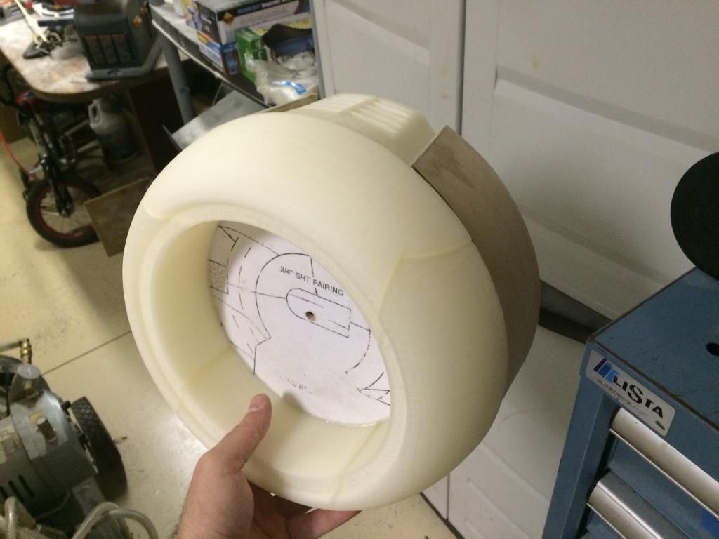
First up was cutting the 1/4" dowel spacers for the front and mid cowl plates. These were then glued to the rear cowl plate, then the front cowl plate glued ensuring the taper and distance between plates was equal all the way around. The 5/16" sq. sheeting supports were then added and everything sanded flush.
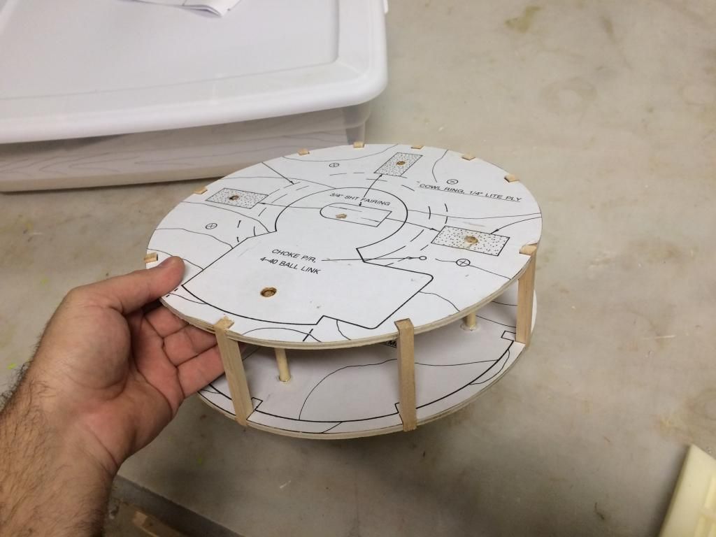
The 1/32" ply cowl flap skin was then centered and glued to the bottim half of the cowl plates.
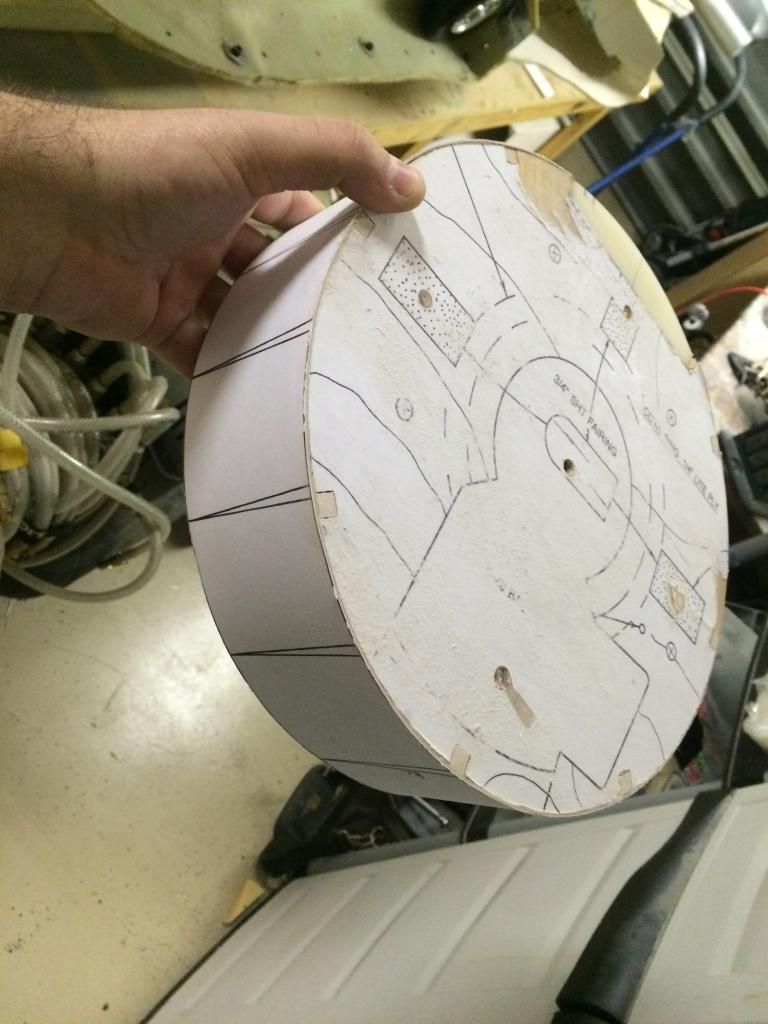
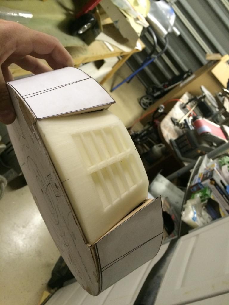
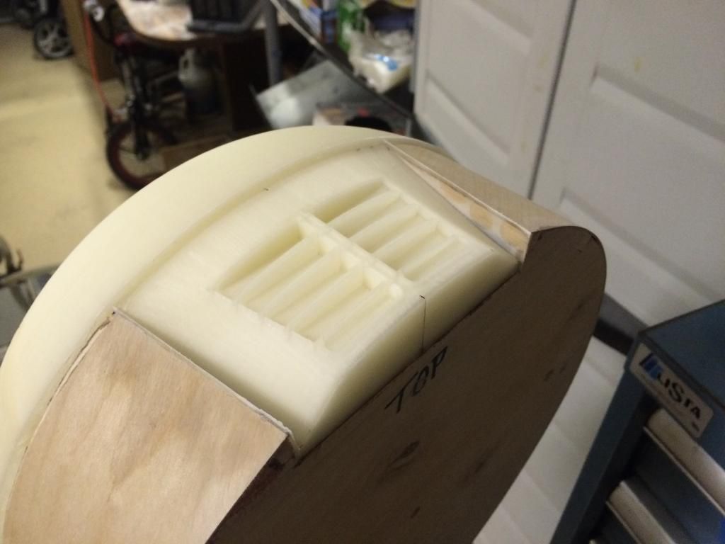
The 3D printed upper cowling vents were then used to determine the size and position of the upper cowl plate cutouts. This was by far the most time consuming. The remainder of the cowl skin was also glued into place.
The 3D printed cowl ring was then assembled and glued to the front cowl plate.
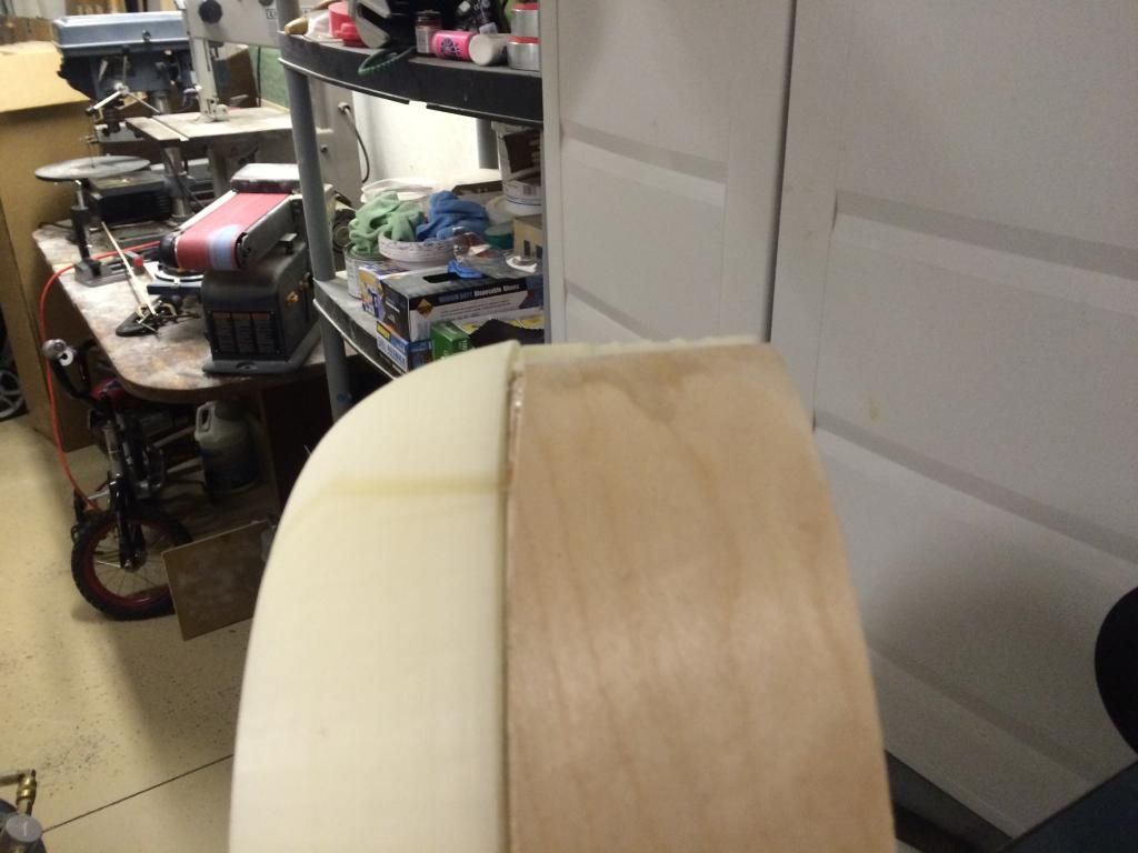
Then the gap between the edge of the upper vents and the cowl flap skin was then covered/filled with a piece of G10.
All that is left is some filling and then some glassing over the wood. Then i can do the detail work and the cowl plug will be done.
First up was cutting the 1/4" dowel spacers for the front and mid cowl plates. These were then glued to the rear cowl plate, then the front cowl plate glued ensuring the taper and distance between plates was equal all the way around. The 5/16" sq. sheeting supports were then added and everything sanded flush.

The 1/32" ply cowl flap skin was then centered and glued to the bottim half of the cowl plates.

The 3D printed upper cowling vents were then used to determine the size and position of the upper cowl plate cutouts. This was by far the most time consuming. The remainder of the cowl skin was also glued into place.

The 3D printed cowl ring was then assembled and glued to the front cowl plate.


Then the gap between the edge of the upper vents and the cowl flap skin was then covered/filled with a piece of G10.

All that is left is some filling and then some glassing over the wood. Then i can do the detail work and the cowl plug will be done.
11-28-2014, 06:27 PM
#56
Nice work! I am pushing really hard on my 1/4 scale as well. Almost done with the sheeting. I wanna start glassing soon, as my goal will be to shoot paint around x-mas.
While we are on the cowl, I am pondering how to make the cowl flaps functional. I was planning on the cable method, but the fixed area on the top, and also the gap on the bottom where the engine cylinder exits, breaks the loop, that is required to do the cable thing. I am thinking maybe a golden rod sleeve, in nyrod on each side, hooked up to a servo on each side. This tube would rotate torsionally, twisting to open and close the flaps.
While we are on the cowl, I am pondering how to make the cowl flaps functional. I was planning on the cable method, but the fixed area on the top, and also the gap on the bottom where the engine cylinder exits, breaks the loop, that is required to do the cable thing. I am thinking maybe a golden rod sleeve, in nyrod on each side, hooked up to a servo on each side. This tube would rotate torsionally, twisting to open and close the flaps.
Last edited by vertical grimmace; 11-28-2014 at 08:18 PM.
11-28-2014, 11:21 PM
#58
Thomas and all,
I ended up using two flex wires running through tubes, one on each side of the cowl that drive the cowl flaps and even though is not continuous due to the cylinder head, it still works.
When I started, I had the same concern and I built a flex torque cable driving small arms for each cowl flap, but it did not work well. The torque cable was made out of speedometer cable with the arms silver soldered, but it became pretty stiff and did not turn well.
https://www.facebook.com/fly.fliteskin shows a shot video of the cowl flaps
JG
11-30-2014, 08:39 AM
#60
Invert, here are a couple of things you might be interested in. The Concept notes are exceptional. My TA 152 note came with bonus, actual photos.
http://volksusastore.com/scale/index...product_id=829
http://volksusastore.com/scale/index...roduct_id=3075
http://volksusastore.com/scale/index...roduct_id=3189
http://volksusastore.com/scale/index...product_id=829
http://volksusastore.com/scale/index...roduct_id=3075
http://volksusastore.com/scale/index...roduct_id=3189
11-30-2014, 08:44 AM
#61
Thanks VG! your fuse is looking good as well!
I've got the Concept notes for the TA, i'm debating on spending the money on the plastic kit for the 152 and the stuff for the HO229.. I've even been debating on doing another 229 but all composite to try and save some weight and larger 120mm EDF's....to much other stuff to do first though.
thomas
I've got the Concept notes for the TA, i'm debating on spending the money on the plastic kit for the 152 and the stuff for the HO229.. I've even been debating on doing another 229 but all composite to try and save some weight and larger 120mm EDF's....to much other stuff to do first though.
thomas
11-30-2014, 08:55 AM
#62
Thanks Invert.
So, being that I am getting close now, do you think I should peel ply this thing when I glass it? IF so, what do you use? I have some dacron peel ply from aircraft spruce, that seemed to work on a test. I have a bunch of EZ lam resin from ACP composites, that I use when bagging, was thinking of using this, but since you have a lot of experience with this stuff, what is your favorite resin?
Rich
11-30-2014, 09:07 AM
#64
I have had good luck with the EZ lam. It is a 2-1 mix, and I use the 30 min, which is not cured for at least 12 hours.
I am sure I asked this before, but when pell plying the fuse, you have to do this in sections correct. Obviously there is no way to do it all at once. I was also thinking about putting a coat or 2 of clear dope over the wood. Good idea or not?
I am sure I asked this before, but when pell plying the fuse, you have to do this in sections correct. Obviously there is no way to do it all at once. I was also thinking about putting a coat or 2 of clear dope over the wood. Good idea or not?
11-30-2014, 09:10 AM
#65
The dope takes a very long time to finish out gassing, which could cause the fiberglass to bubble away from the surface, its just more weight IMO. For the peel-ply, you can do some area's in large pieces, but compound curves will need to be done in smaller patch's.
12-01-2014, 10:00 PM
#67
I got the bench topper today and came home all raren and ready to get to building the TA-152. First up was trimming the wing overview from the rest and then laying out the parts on the build table.
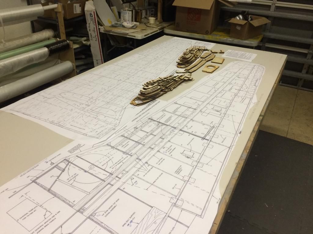
I then started trimming the spruce spars down to length +1" and while the 3D printer was printing the spar standoffs, i started laying out the wing ribs onto the smaller 1/4x1 spruce spar. I also trimmed the wing tube socket to length.
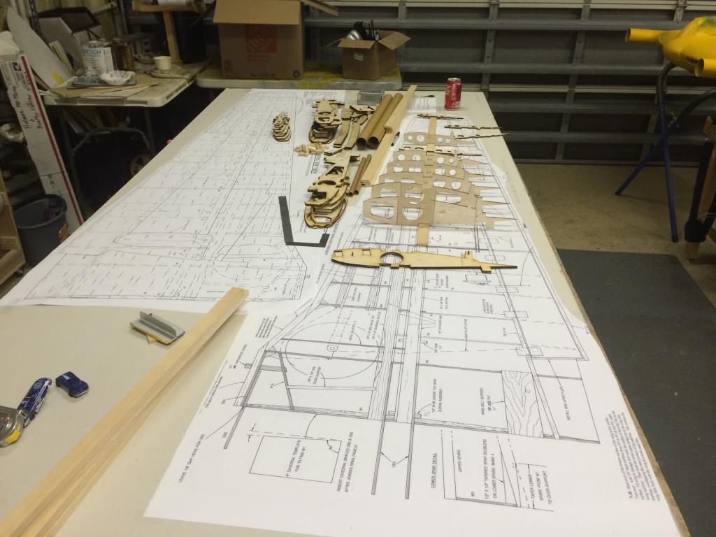
It was about this time when i realized i ordered the wrong wing tube... Ugh, i also found a few spar slots that i made 1/2x1 instead of 1/4x1.
Since the wing ribs were cut for a 2" wingtube, i figured that was probably overkill and it would be nice to have a little extra room for the retract mechanism. So i updated all the necessary wingribs and resent the files to the laser cutter. Feeling like a whipped puppy, i went and did some work on the pancake.
12-01-2014, 10:30 PM
#68
That must be really nice having a laser cutter. I may have to look into a cnc cutting system, either a router or laser. Have not looked in a while, and hopefully the prices have dropped some.
I was wondering what you were going to do with some of the dimensions of the sticks, and the wing tube, as it would not seem necessary to just scale them up 125%. Plus, you would want them to be a standard size, unless ripping this out yourself as well on the table saw etc.
I was wondering what you were going to do with some of the dimensions of the sticks, and the wing tube, as it would not seem necessary to just scale them up 125%. Plus, you would want them to be a standard size, unless ripping this out yourself as well on the table saw etc.
12-01-2014, 10:35 PM
#69
Thats the beauty of doing things by 25/50/75/100% enlargements, the sheet/stick dimension upsize to the next available size roughly 60-80% of the time.
Ive got a small 12x16 cnc router that i use for alot of stuff, but all of my laser cutting is outsourced. I have been looking into purchasing a 24x36 laser cutter though, but i need a 24x48 cnc router more than a laser cutter.
Ive got a small 12x16 cnc router that i use for alot of stuff, but all of my laser cutting is outsourced. I have been looking into purchasing a 24x36 laser cutter though, but i need a 24x48 cnc router more than a laser cutter.
12-01-2014, 10:53 PM
#70
I actually just got a kit from Eureka aircraft, and noticed all the wood was CNC routed. Looks like they used a .125" cutter. I am sure you can go smaller, as I cut templates out at work with a 2 mm carbide cutter, no prob. That could certainly handle plywood and balsa.
The problem you always see with the laser, is they do not like harder thicker material. The feed rate has to drop, and then you get fire. So a router may be the ticket for the harder plywood. Only problem there is you will not get a sharp shoulder cut in stringer notches. These would have to be chased with a file. Again here, the smallest diameter cutter possible would be the ticket.
The problem you always see with the laser, is they do not like harder thicker material. The feed rate has to drop, and then you get fire. So a router may be the ticket for the harder plywood. Only problem there is you will not get a sharp shoulder cut in stringer notches. These would have to be chased with a file. Again here, the smallest diameter cutter possible would be the ticket.
12-02-2014, 04:59 PM
#72
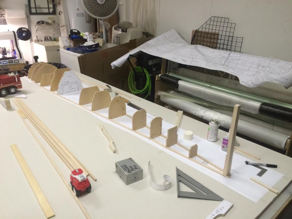
Not to be one to let a little set back, set me back. I pulled out the parts and began building the fuse. First up was laying out the top view of the plans and building the Fuse crutch. The 1/5 size material is 1/4" sq, the 1/4 scale size is 5/16" sq. this is why i go with enlargements o 25/50/75/100, most all of the time, the materials upsize to the next normal dimension thickness.
After the crutch was made up, the fuse bulkheads were positioned and glued to the crutch.
For those who build this thing, dont glue F14 and 15 in place yet. Once you have the Vertical stab TE glued in place and the lower stabilizer saddle glued to the VS3 and F-16, use the lower stab saddle to get the proper forward lean of F15 and glue in place.
For F14, you'll have to measure along the stringer line that goes from F13/14 and onto the upper horizontal stab saddle.
Otherwise on the read side of the fuse, theres not alot of surprises. I do wish this thing had more stringers along the rear fuse just to make sheeting easier and to stiffen up the fuse before sheeting.


