


Top RC Zero from Gator R/C
 02-28-2022, 06:43 AM
#1001

My Feedback: (2)
CK1 Thanks for the tip. If I understand your instructions correctly, those were my intention in the beginning. However, I have some concern about long term vibration from the engine being transferred directly to the cowl?
I may or may not do that in the end. It would be nice not to have mounting bolts on the outside of the cowl. First, I need more trial fitting to make certain the prop hub is centered in the middle of the cowl opening.
On another issue regarding the pull-pull cables, did you install as directed in the manual, or modify the installation? I am concerned because the cables stretch and do not hold the rudder securely.
Regards - J Tab
Last edited by Jaketab; 02-28-2022 at 06:46 AM.
 02-28-2022, 07:07 AM
#1002


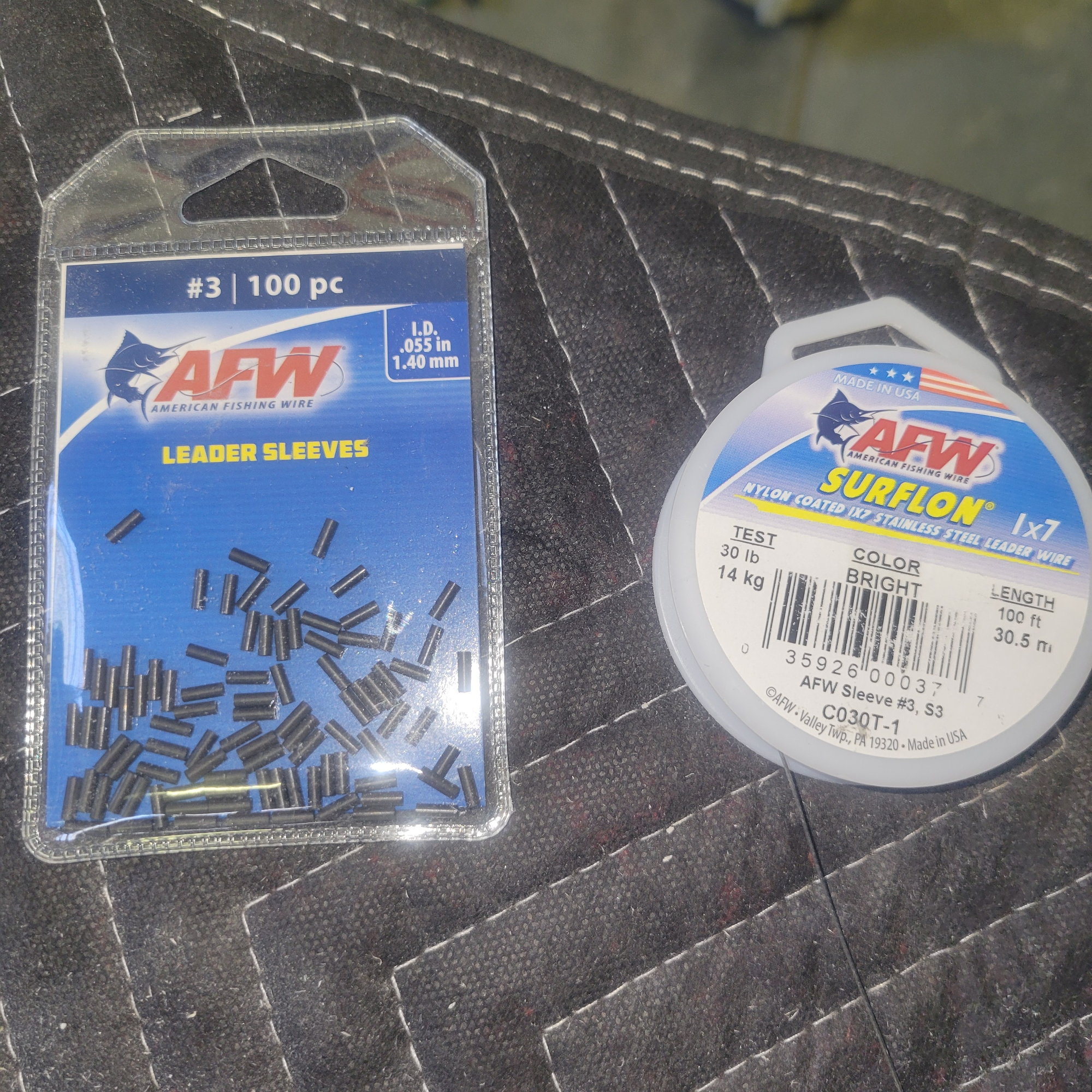
If you're using the supplied cable and crimp sleeve, you probably will not be satisfied with the stretch . I always use AFW Surflon 1x7 cable and #3 sleeves on all pull pull setups . There is still some relaxation in the cables, but most of that is caused by structural compression .BTW , vibration on these radials is minimal and much less than any 2 stroke single or twin . Unless you run unbalanced props, you won't have an issue with vibration effects on the cowl mount
Last edited by CK1; 02-28-2022 at 07:09 AM.
 03-04-2022, 12:27 AM
#1005
For those who are thinking and will be installing smoke system: heating coil is a must!
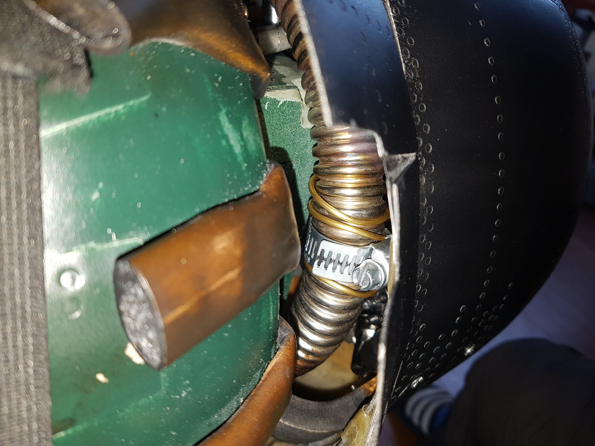
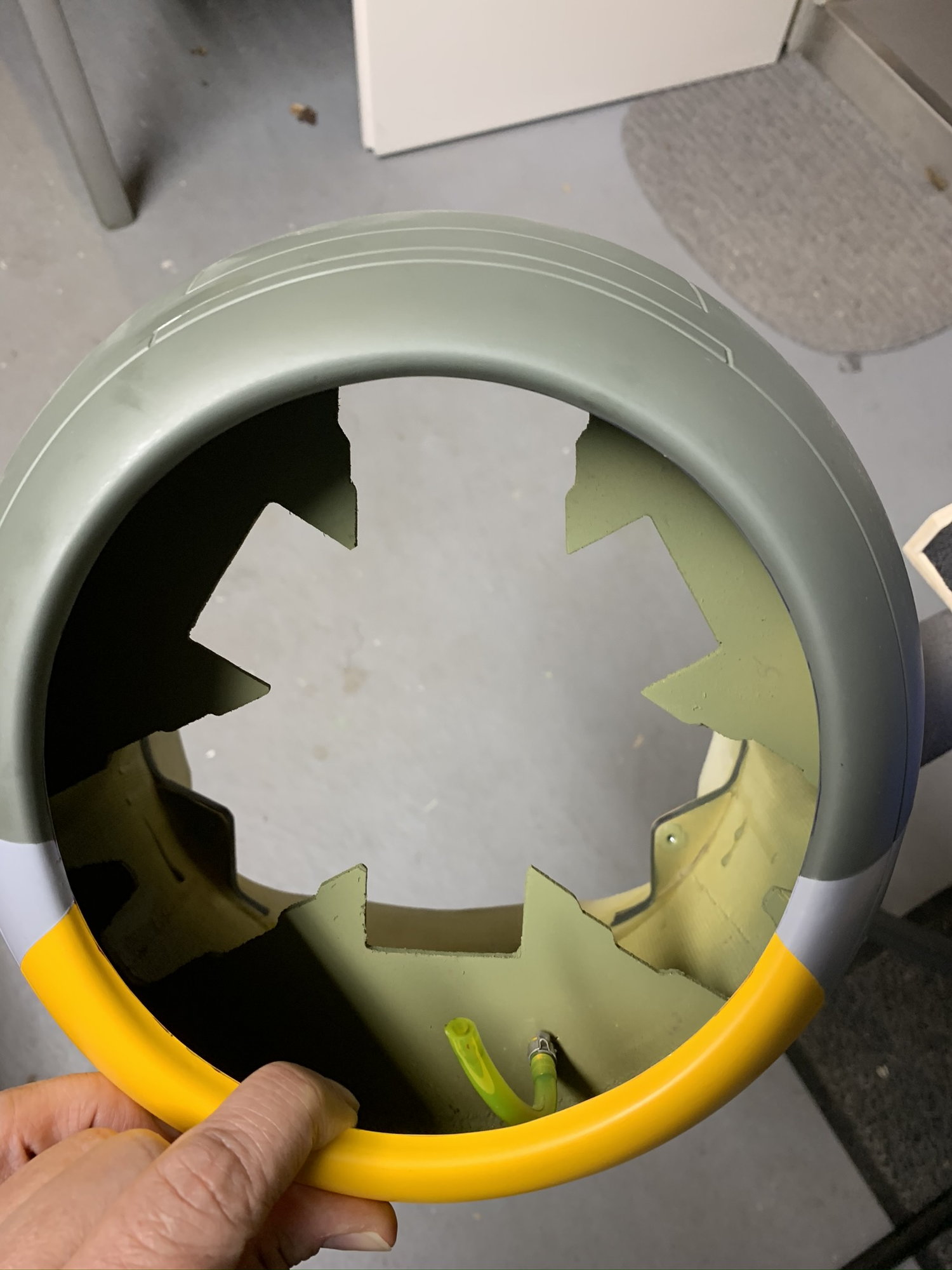
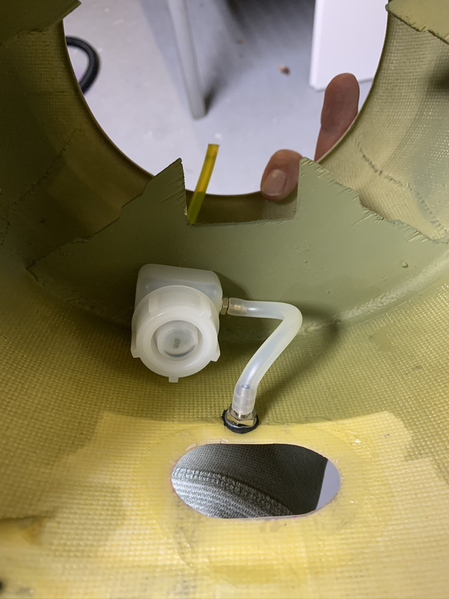
In the begining I just installed diy spray nozzle in the ring muffler close to cyl. No1 and connected to the pump directly. Result was not good enough. Even with smoke pump running on minimum rpm visible ammount of smoke fluid was dropping from exhaust unburned.
Then I took 2mm diam. copper pipe and wrapped few coils around the exhaust ring. I used metal band to keep it tight to the ring. In this way fluid is nicely preheated before it gets to the nozzle. Result: all smoke fluid is burned inside the exhaust ring giving more visible smoke.
03-07-2022, 08:57 AM
#1006

Hi Folks,
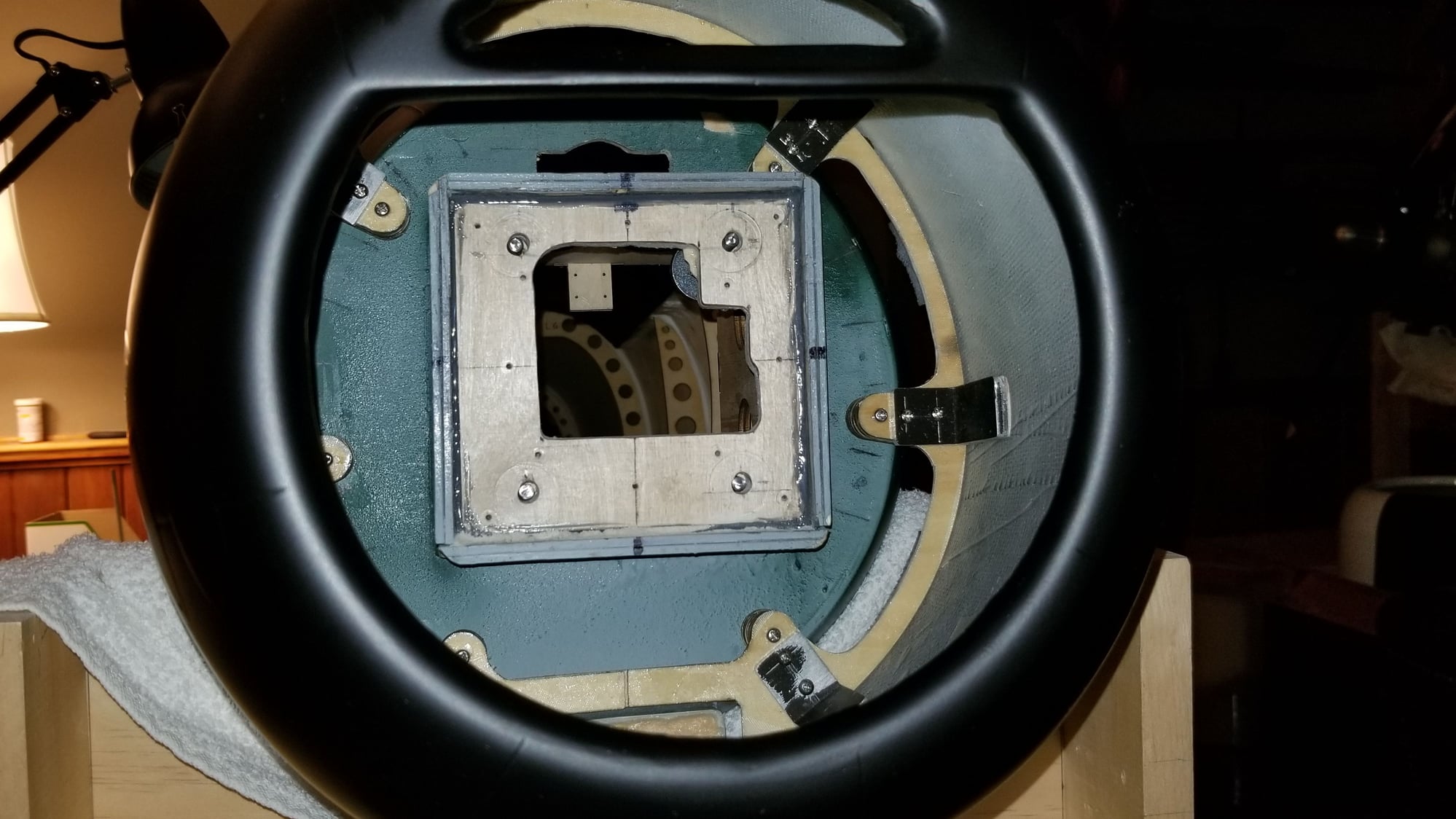
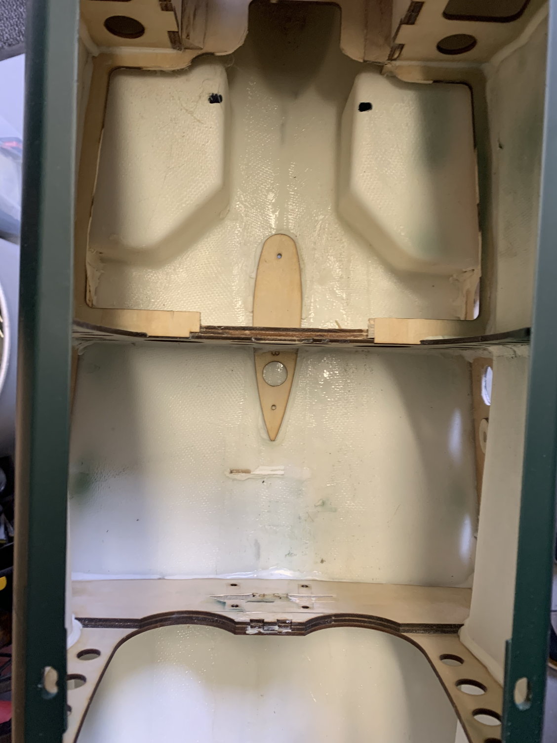
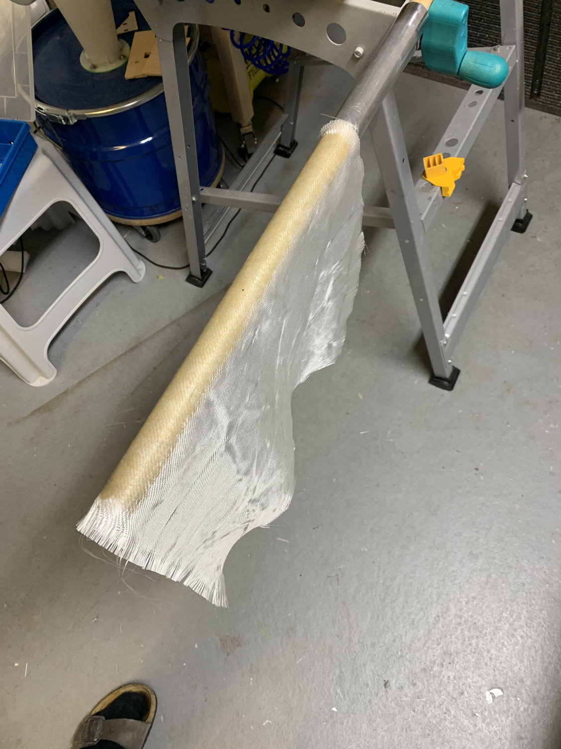
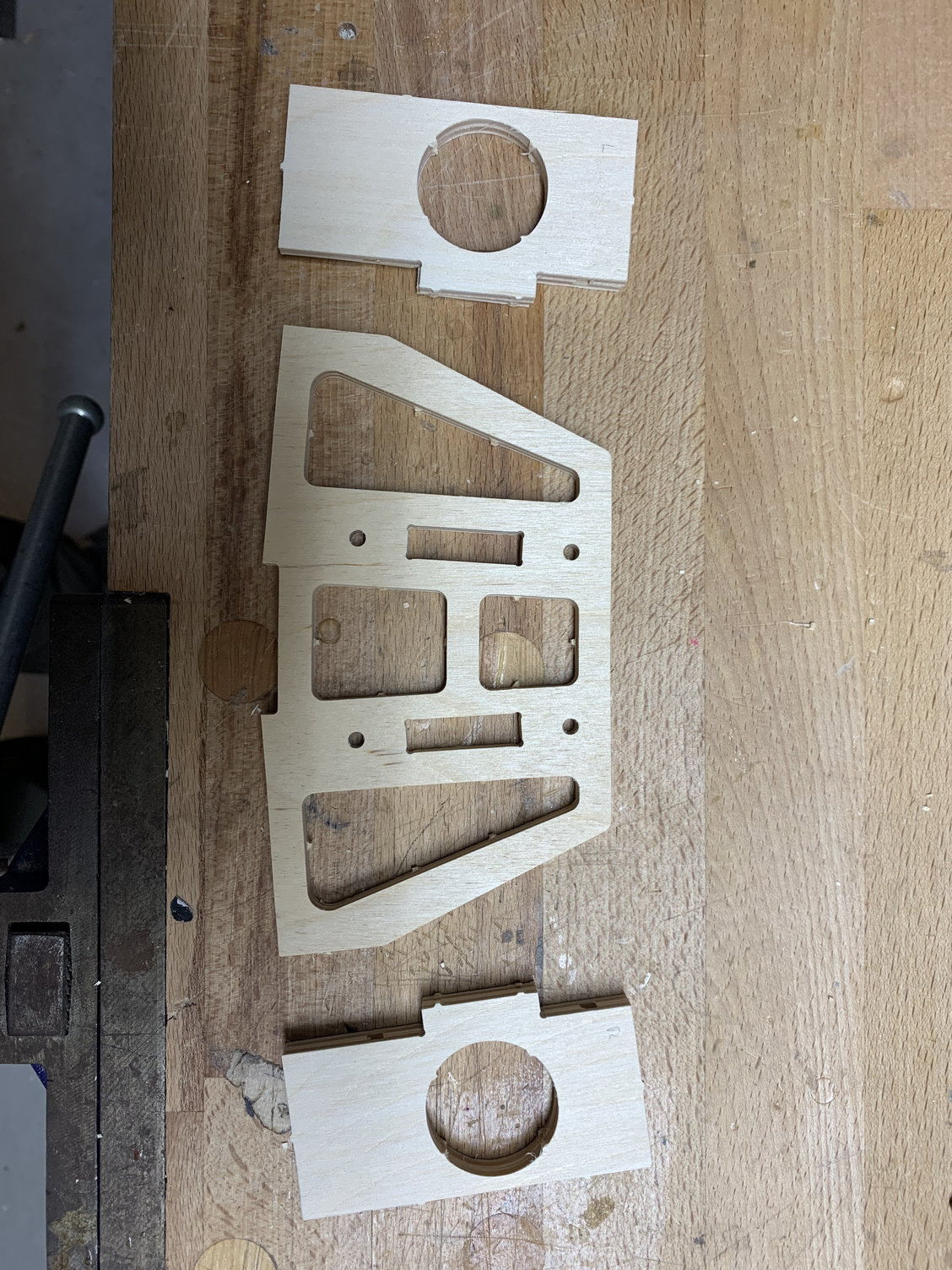
since some guys reported a possible weakness of the fuselage tube mounts I checked this area... and the Fuselage formers were bending under load
As the aluminium tubes had massive play in the fuselage as well, I decided to go all the way.
since some guys reported a possible weakness of the fuselage tube mounts I checked this area... and the Fuselage formers were bending under load
As the aluminium tubes had massive play in the fuselage as well, I decided to go all the way.
 03-07-2022, 09:11 AM
#1011
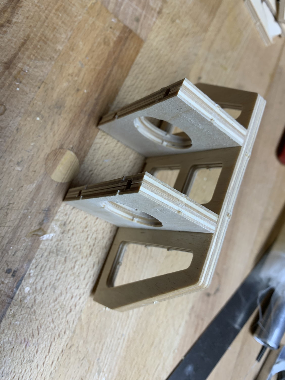
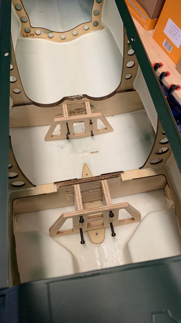
The rear tubing is carbon, because it is well behind the cg and the saved weight should help balancing the plane.
I used the heavy 30mm aluminium tube, because it had a perfect fit in the wing and is pretty beefy
Best regards,
Juergen
I used the heavy 30mm aluminium tube, because it had a perfect fit in the wing and is pretty beefy
Best regards,
Juergen
03-07-2022, 10:58 AM
#1013
 03-07-2022, 11:54 AM
#1016
Your pictures shows system which real Zero had. Nice but more complicated, however there is enough space to make it.
My is easier to do and works pretty well, but.... if I did it again I would give up working flaps and make them fixed in opened position.
Only advantage of working flaps: you can show them to your friends at the airfield But having Saito, before starting up the engine you have to put them to opened position and keep like that for entire flight.
My is easier to do and works pretty well, but.... if I did it again I would give up working flaps and make them fixed in opened position.
Only advantage of working flaps: you can show them to your friends at the airfield
But having Saito, before starting up the engine you have to put them to opened position and keep like that for entire flight.
03-07-2022, 12:15 PM
#1017
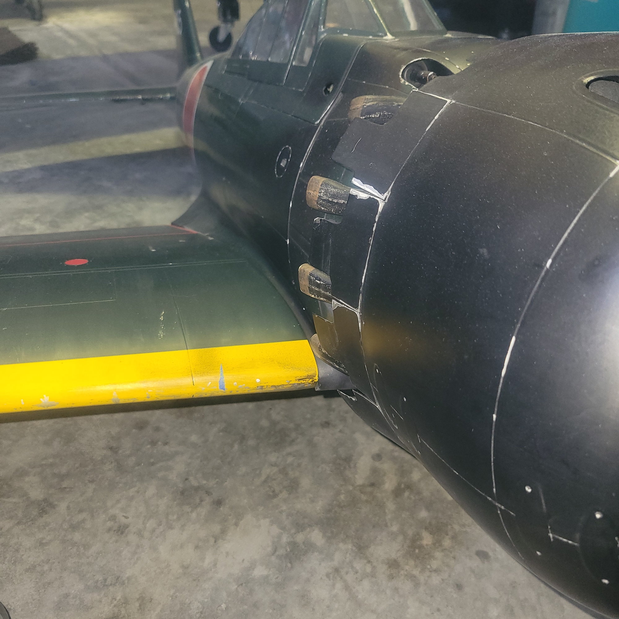
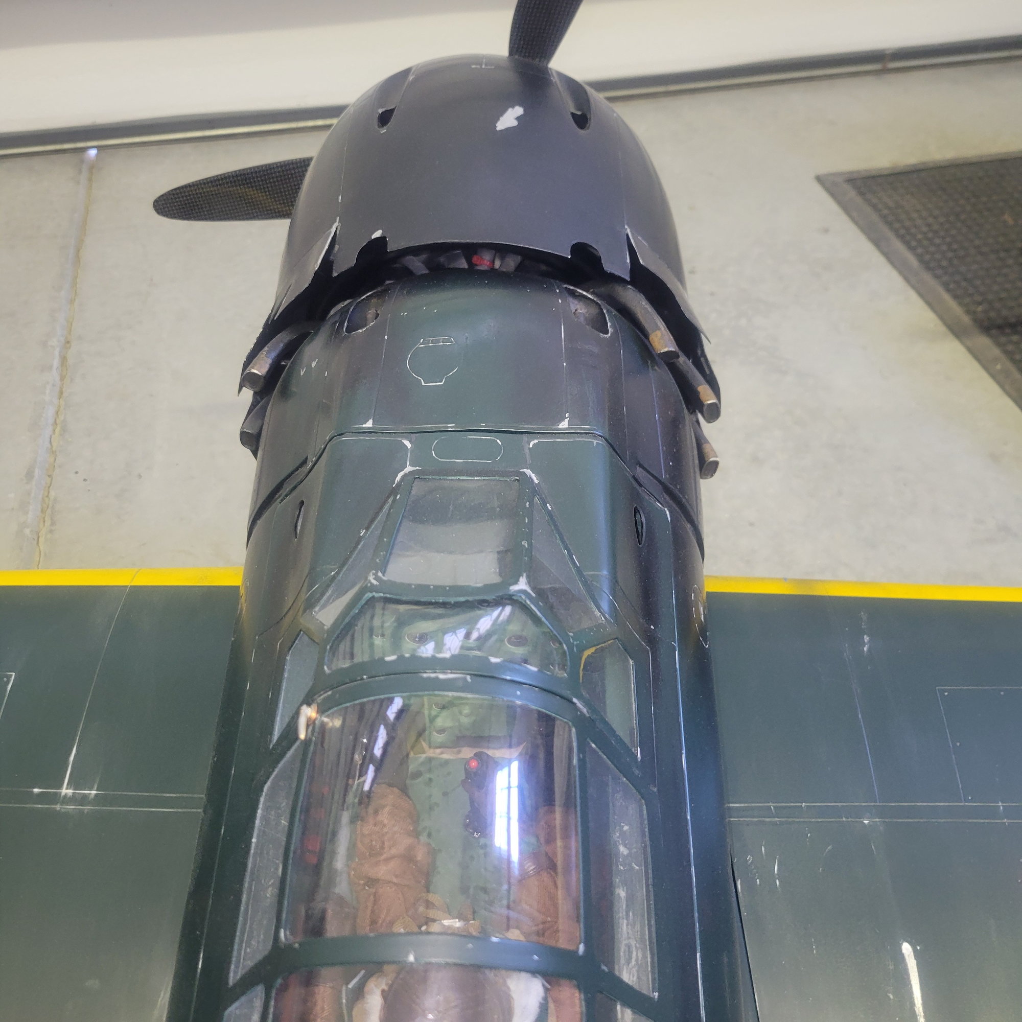
Here is Top RC Zero cowling with working flaps made by Toshiaki Nakayama. This guy detailed his model on highest level I've ever seen. Unfortunately was crashed due to elevator servo malfunction 
03-07-2022, 10:30 PM
#1019
Thanks for your thoughts, guys!
I plan on linking the flap position to the engine temperature via telemetry when the aircraft is clean and in flight and have them fully open as long as flaps and gear are extended.
I have a Powerbox Core radio which has logical switches and telemetry switches�
Regards,
Juergen
I plan on linking the flap position to the engine temperature via telemetry when the aircraft is clean and in flight and have them fully open as long as flaps and gear are extended.
I have a Powerbox Core radio which has logical switches and telemetry switches�
Regards,
Juergen
03-08-2022, 05:06 AM
#1020
Senior Member
Thanks for your thoughts, guys!
I plan on linking the flap position to the engine temperature via telemetry when the aircraft is clean and in flight and have them fully open as long as flaps and gear are extended.
I have a Powerbox Core radio which has logical switches and telemetry switches�
Regards,
Juergen
I plan on linking the flap position to the engine temperature via telemetry when the aircraft is clean and in flight and have them fully open as long as flaps and gear are extended.
I have a Powerbox Core radio which has logical switches and telemetry switches�
Regards,
Juergen
03-11-2022, 08:49 PM
#1021
My Feedback: (2)
As my Zero nears completion, just a few more questions please.
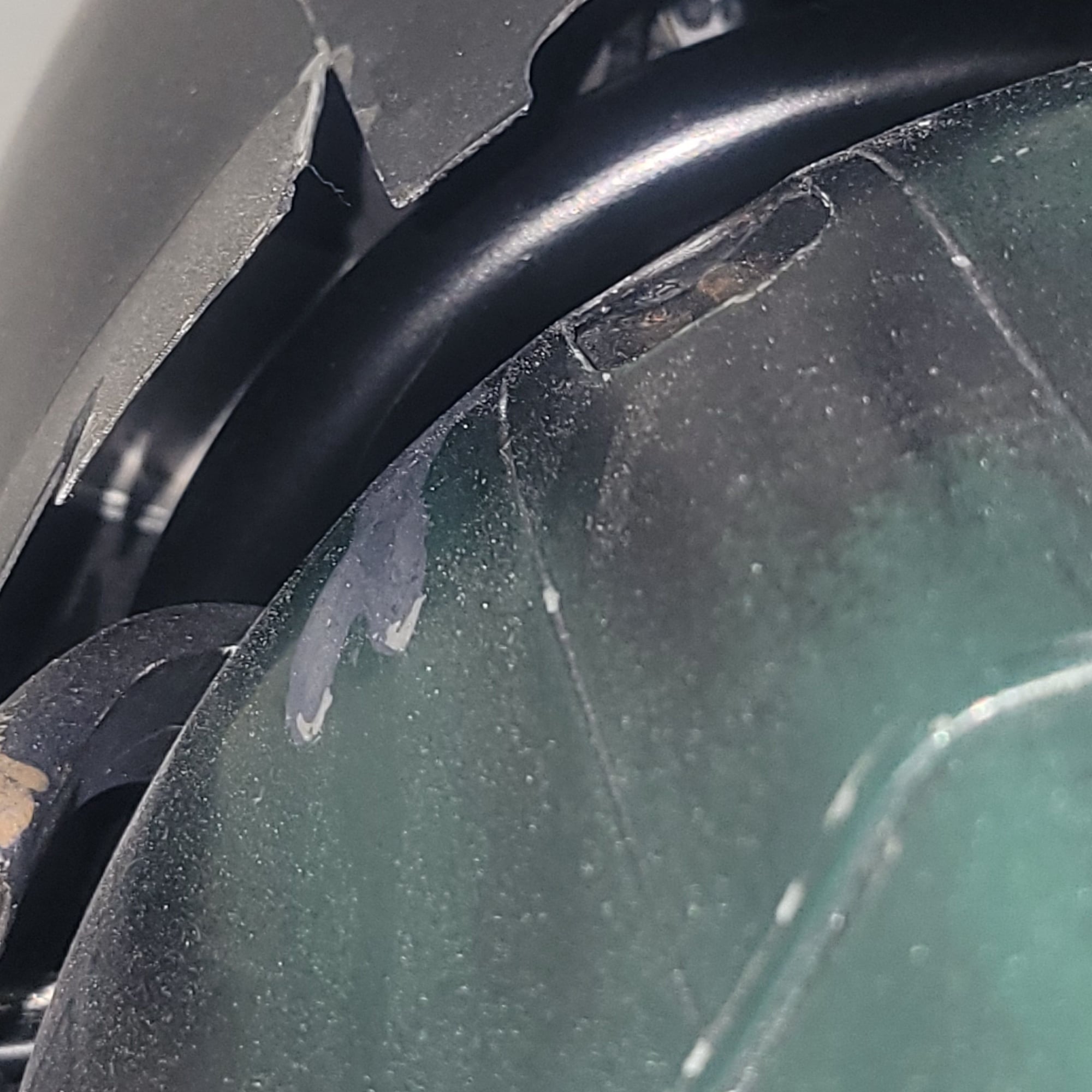
*I'm in need of touch up paint where some paint came up with masking tape. Does anyone know the exact color green of the TRC Zero and is there an off the shelf model paint color that will match?
I tried Tamiya XF-61 and it was too dark.
*I don't look forward to the bleed oil mess from the crank vent line. Where is a convenient place that most use to exit the bleed line from the plane?
*Where are you placing the fuel vent exit line?
*From reading through this thread, I expect to add about 1 lb. of lead to the motor box?
The batteries are in the compartments on each side of the fuel tank. I'm using a 500 ml Fiji bottle for the tank. If that proves not enough, I'll change out to a 700 ml tank.
My set up includes the Saito 90 with Keleo ring. Two 7.4v 3400 milliamp Li Ion's for the radio and sharing an IBEC for the ignition. A separate 3400 milliamp for the Robart electric gear. Hitec D645 servos all around.
Thanks - J Tab
The following users liked this post:
Giant Flyer (10-10-2023)
 03-13-2022, 05:06 AM
#1023
My Feedback: (2)
Juergen - That is a clever solution. I use a catch bottle on my Valach 210.
I have an idea, but I'm not certain it will work as it should. What about running a line from the bleed nipple and tap into the lower exhaust stack of the Keleo ring? A check valve would be installed to prevent back flow.
It would not eliminate of the mess, but some of the oil may be burned to help reduce it. Any ideas or thought on this????
Regards - J Tab
03-13-2022, 05:54 AM
#1024
If you tap it into the exhaust I wouldn�t be concerned about back flow. Not enough pressure. But not enough temperature either to burn the oil. Just a little more smear coming out of the exhaust�