


New Giant Top Flite F6F Hellcat coming soon?
 03-29-2020, 05:03 PM
#451

Capt John,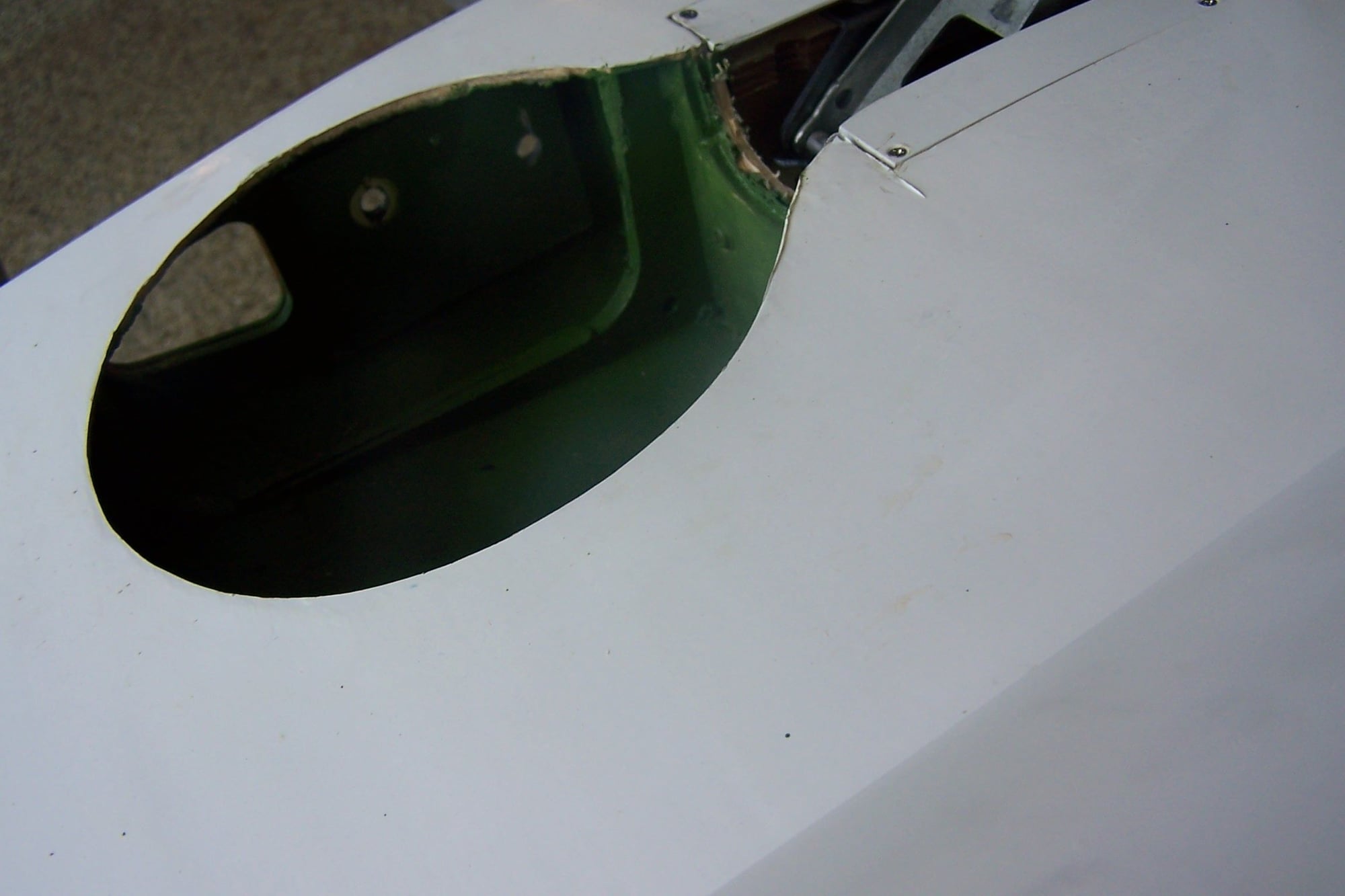 m
m
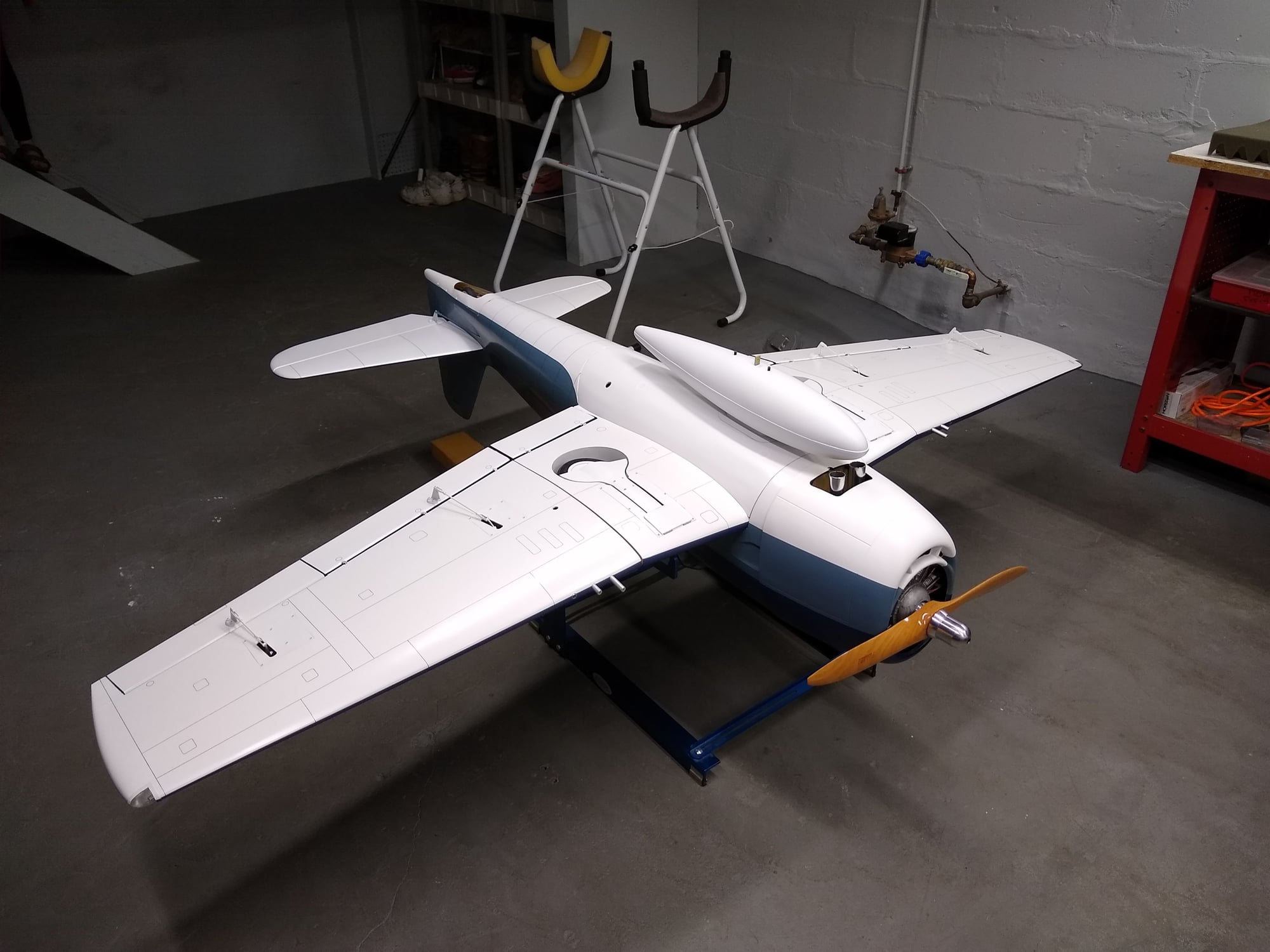
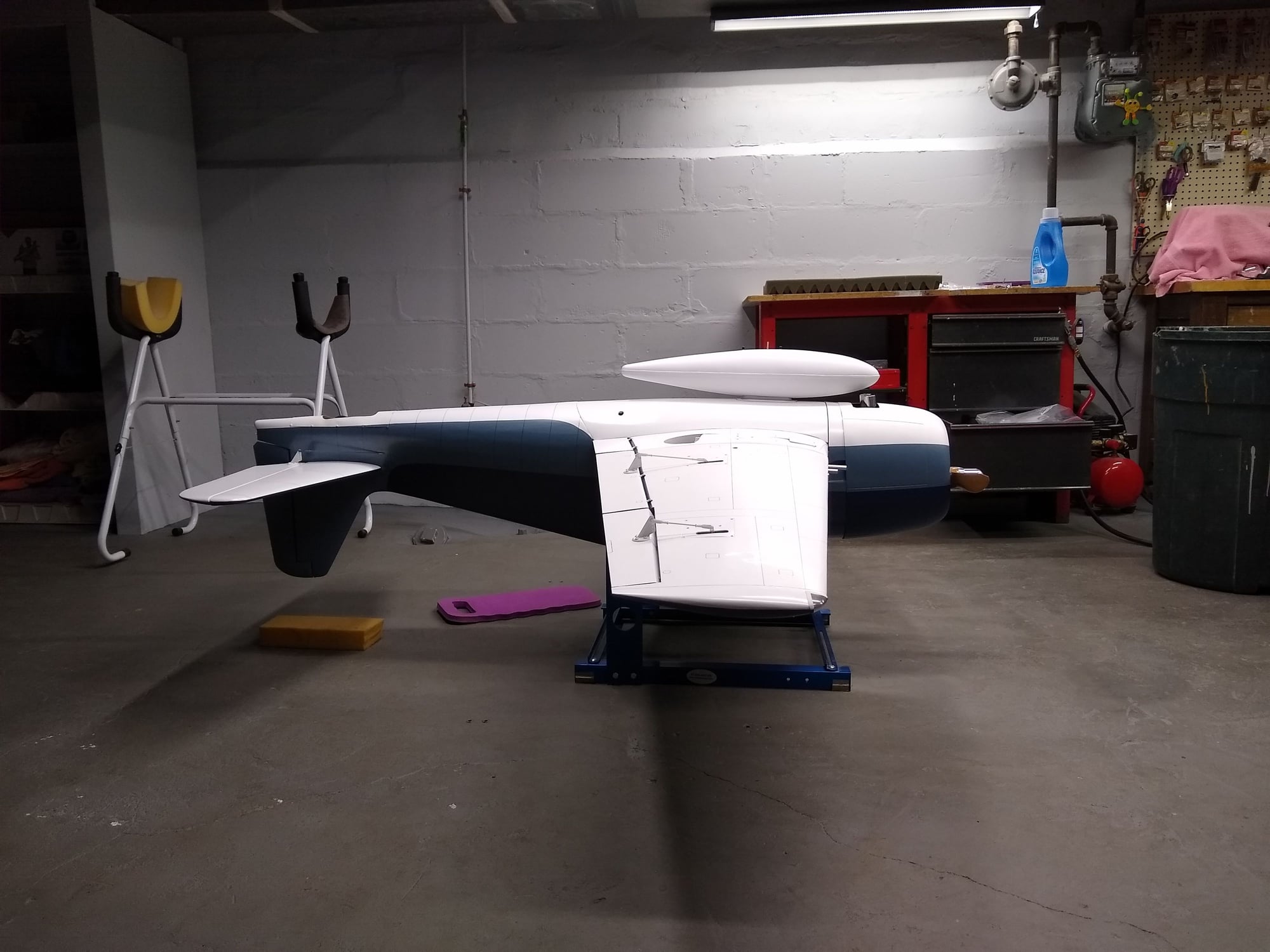
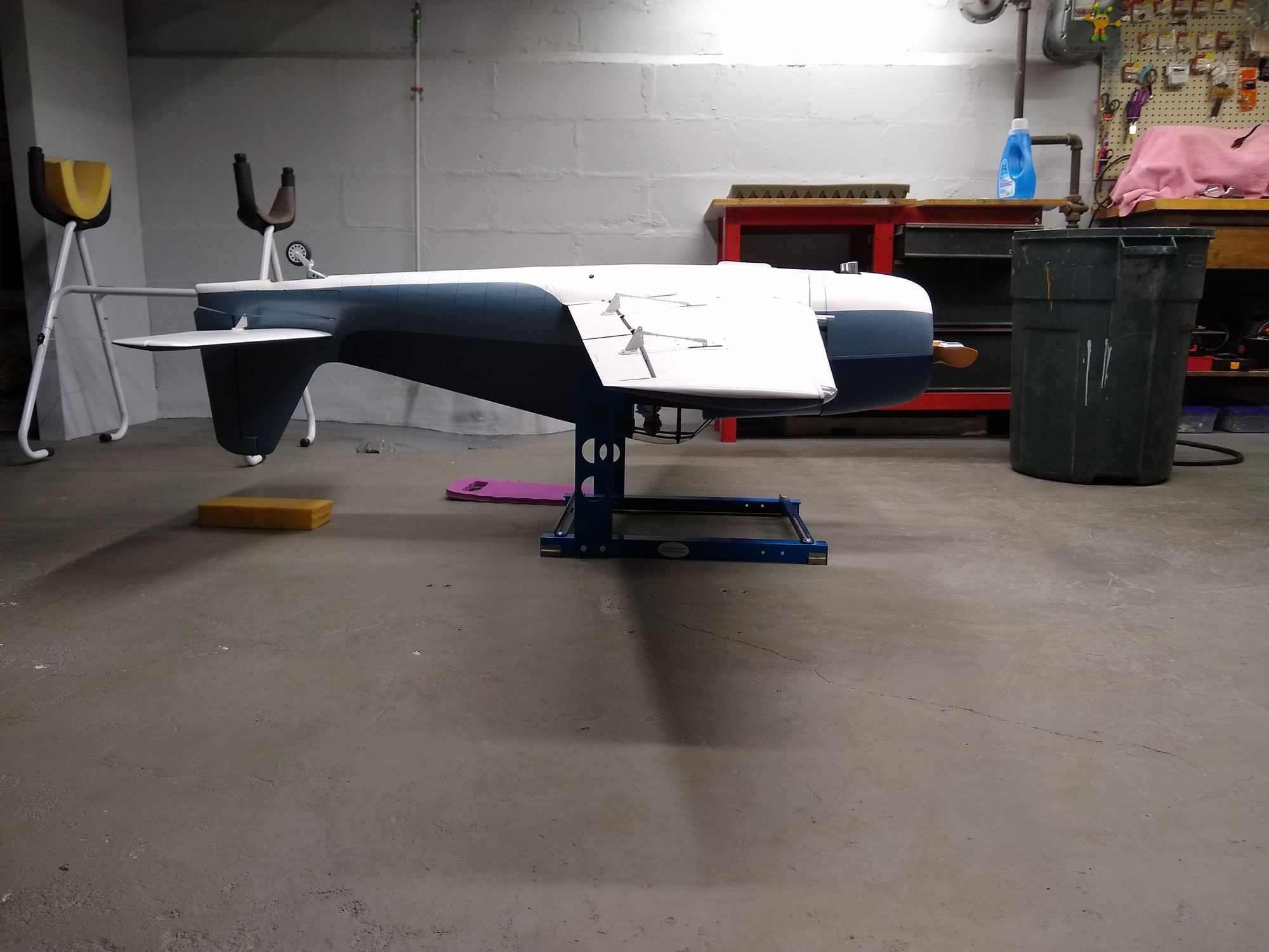
The flap joiner is installed in the inner flap. With regard to securing the outer wing panels, the builder installed a 1/4" blind nut in the last rib of the wing and used a 1/4" wing bolt to secure the wing. The bolt is shorted and must use a short screw driver in the wheel well to tighten. It works. The DLE 61 turns the 21-10 3 blade at 6,150 rpm. I didn't tack the 2 blade. I think I'll test fly with the 22-10 two blade. I cost less.
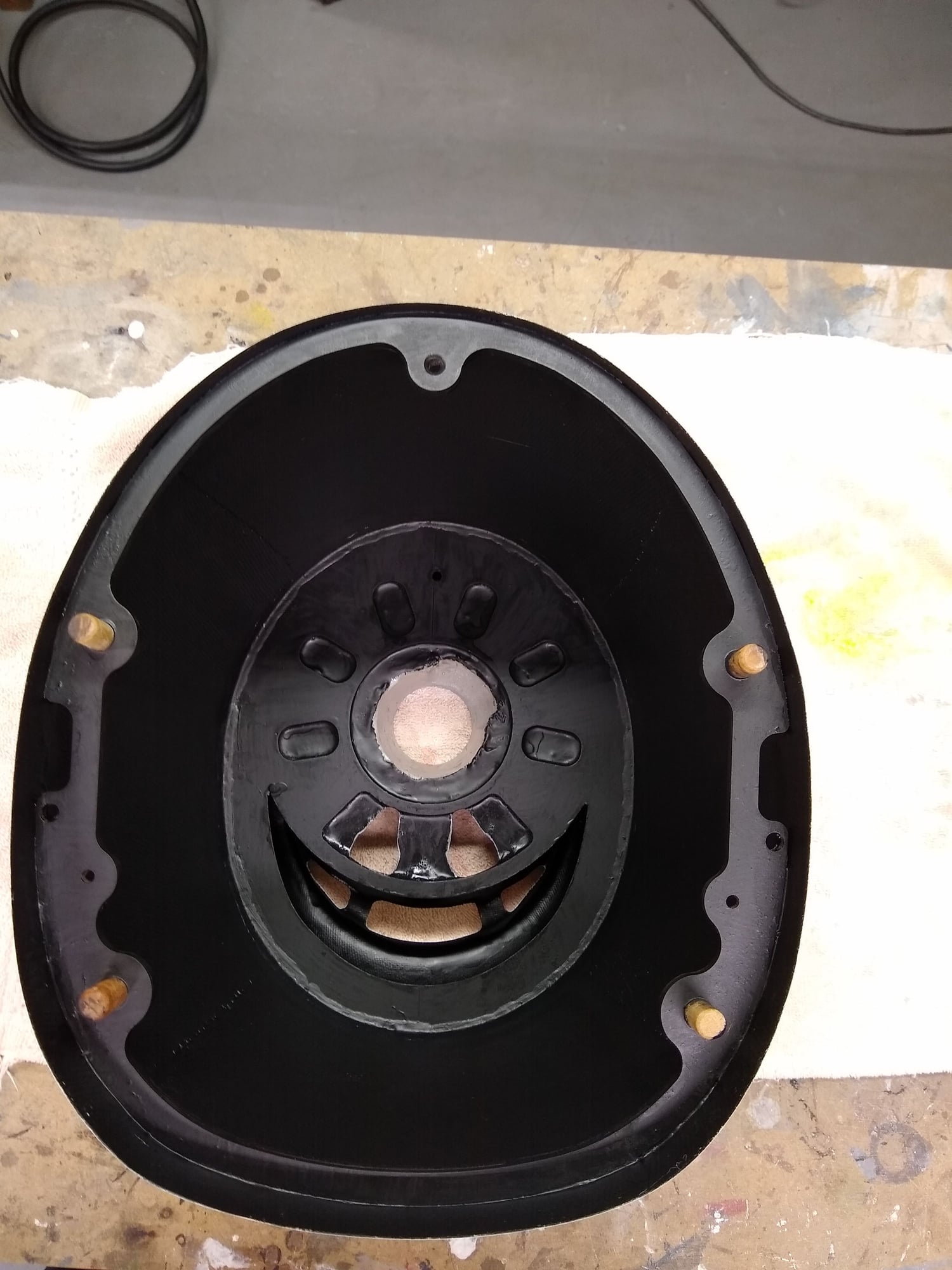
The front hole is the one used.
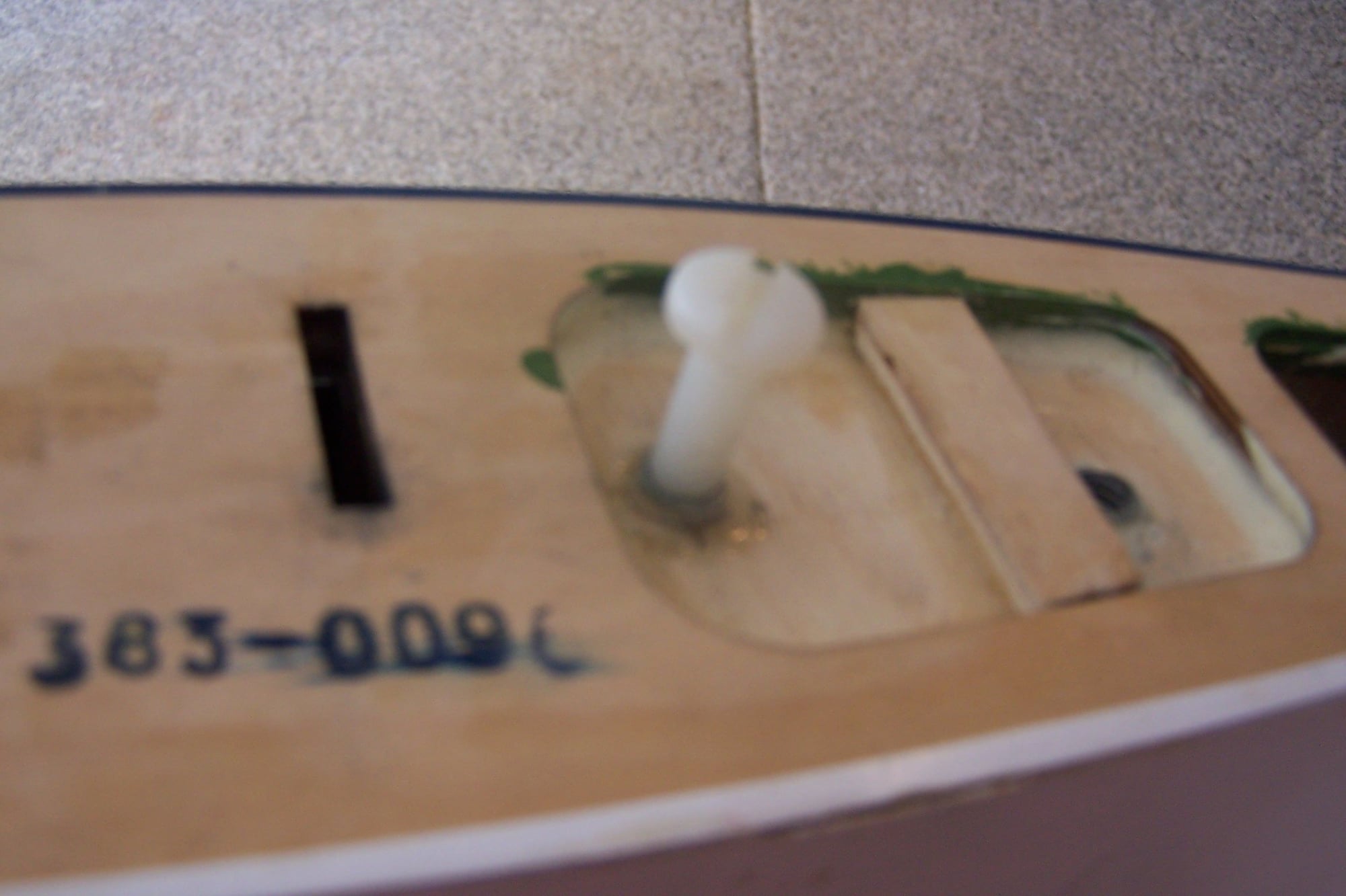
You can seen the ply was added to hold the nut.
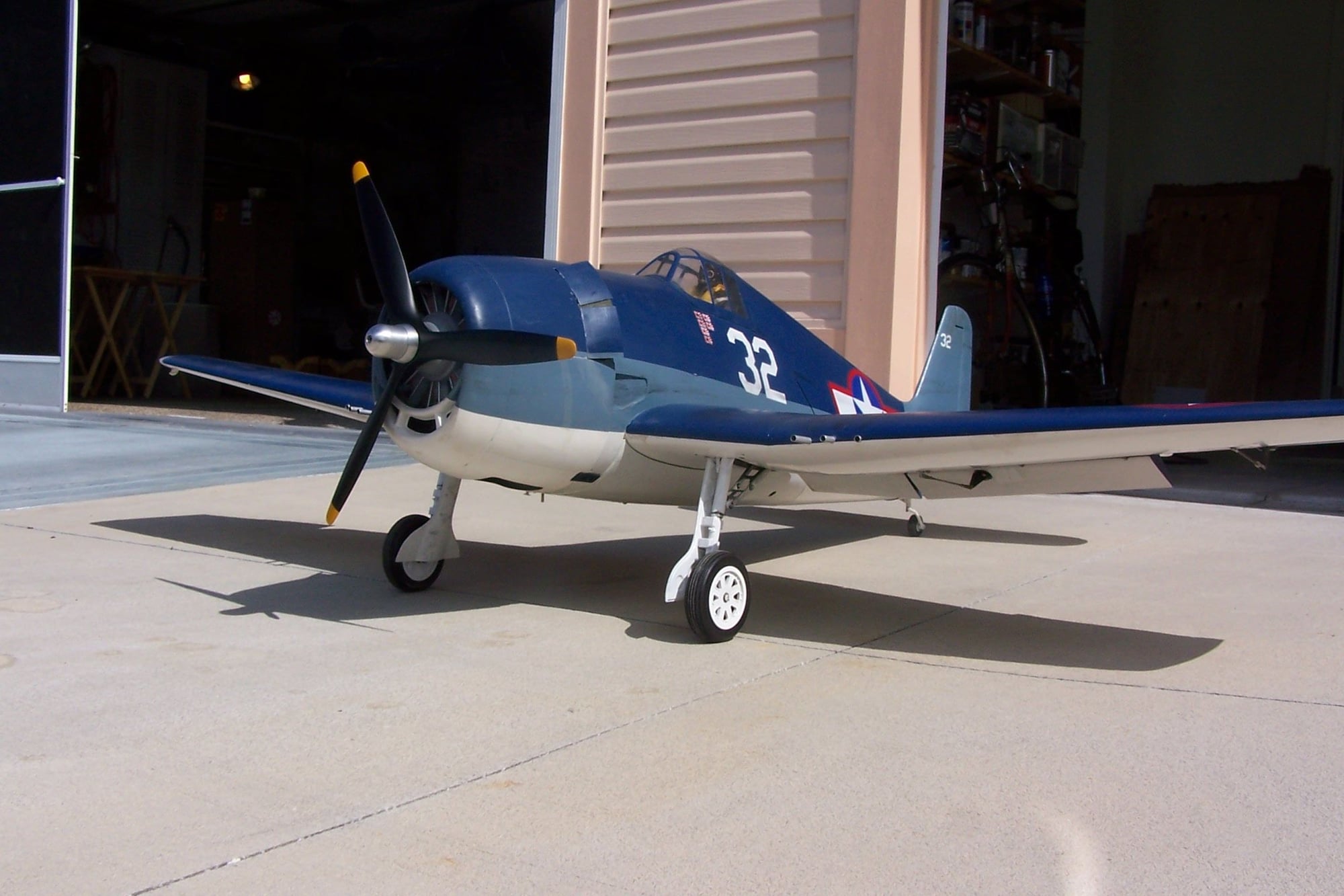
I think the 3 blade looks good.
m The flap joiner is installed in the inner flap. With regard to securing the outer wing panels, the builder installed a 1/4" blind nut in the last rib of the wing and used a 1/4" wing bolt to secure the wing. The bolt is shorted and must use a short screw driver in the wheel well to tighten. It works. The DLE 61 turns the 21-10 3 blade at 6,150 rpm. I didn't tack the 2 blade. I think I'll test fly with the 22-10 two blade. I cost less.
The front hole is the one used.
You can seen the ply was added to hold the nut.
I think the 3 blade looks good.
Last edited by RBean; 03-29-2020 at 05:08 PM.

 03-29-2020, 09:53 PM
#453

The reason to do it this way is because in the worst case scenario if you run out of gas completely the plane will be balanced neutral. When the gear deploys forward the CG will shift nose heavy and add drag. With a little bit of gas left at the end of a flight the plane will be slightly nose heavy but still very responsive when landing.
Just balance the plane neutral and it will be just fine.
03-30-2020, 02:47 AM
#455

The picture in the manual very clearly shows the gear retracted and advises that all attachments you intend to fly with be attached. Balance point is stated at 6 inches with the option of 6 and 5/8ths as the rearmost recommended point. Not much room for interpretation on this issue.


 03-31-2020, 01:18 PM
#457
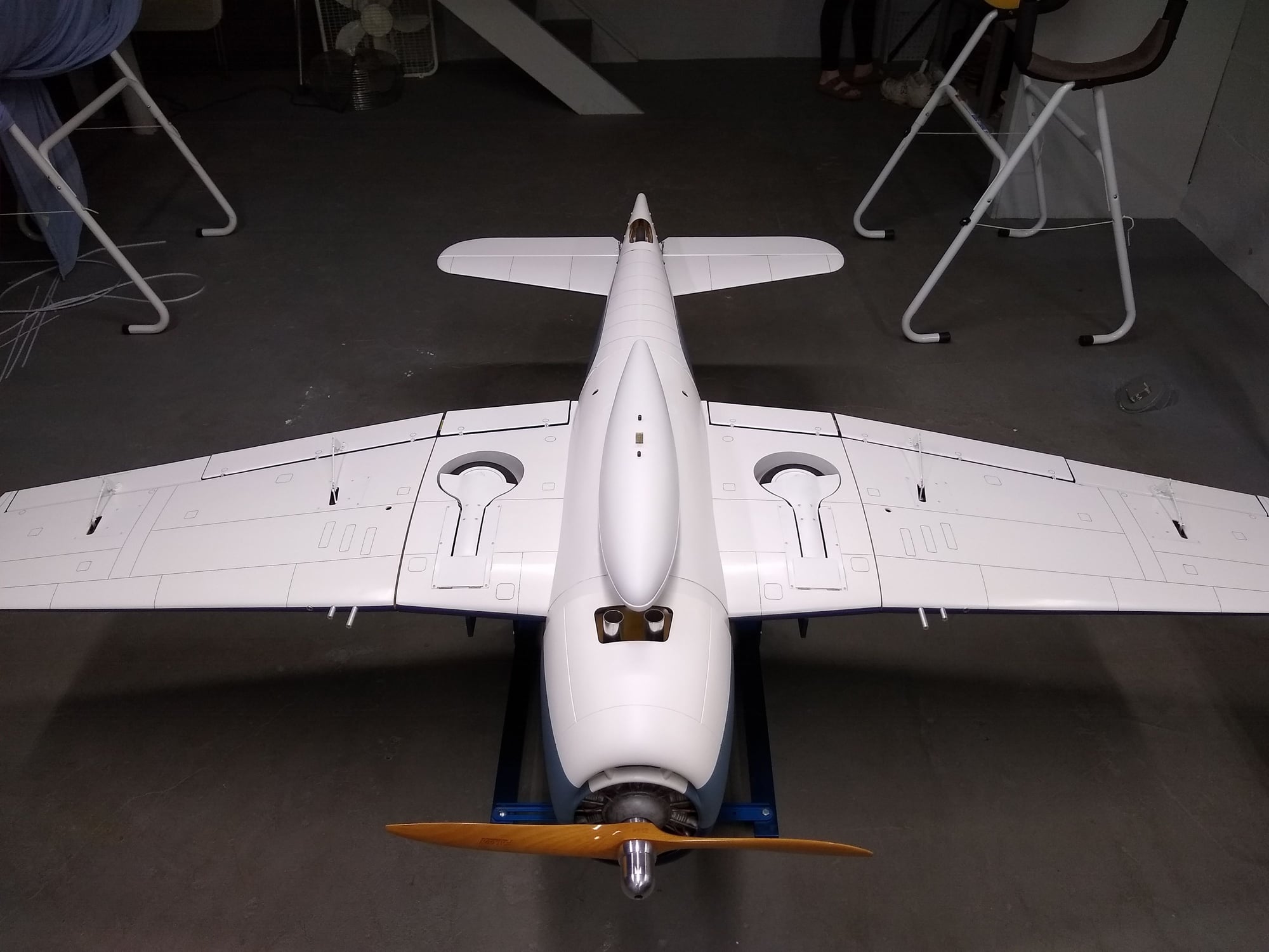
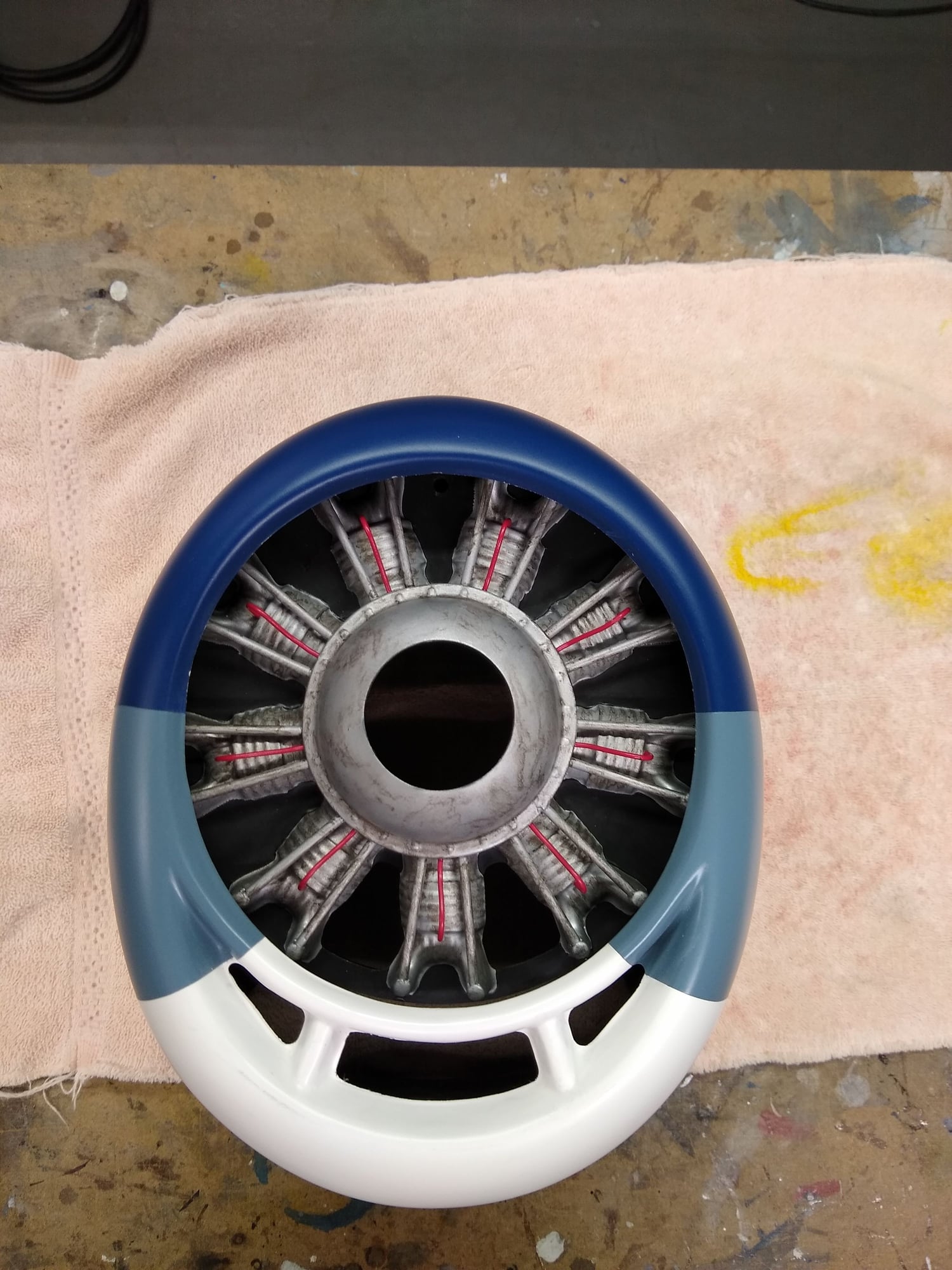
Mine balances dead level at the 6" mark with an empty tank and all equipment and batteries installed. Dropping the gear changes the CG dramatically and the model becomes very nose heavy. If that is the spec I guess I wont worry about it. I did not add any weight except for filling the dummy radial and engine case completely with Epoxy.
03-31-2020, 01:24 PM
#458
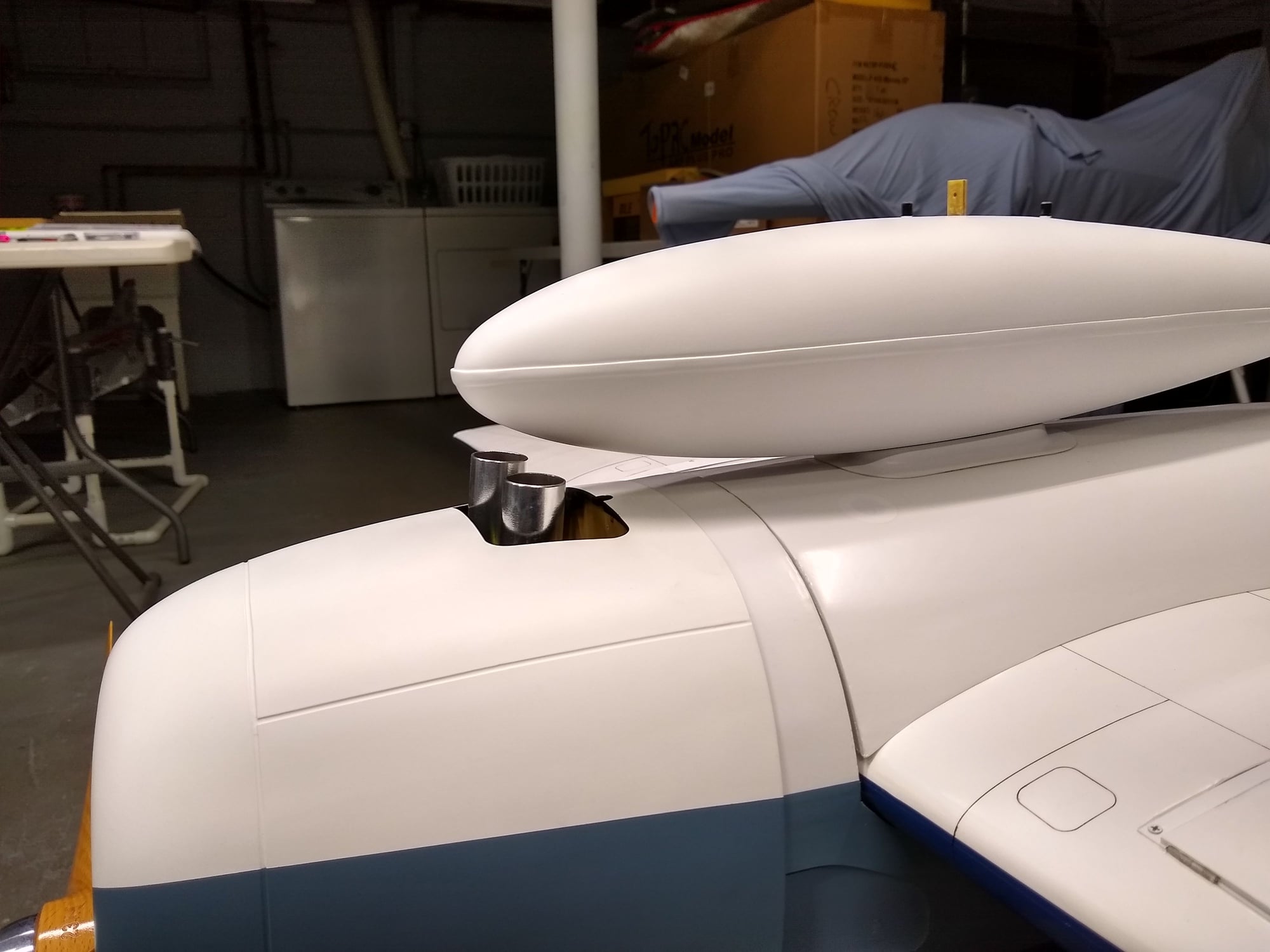
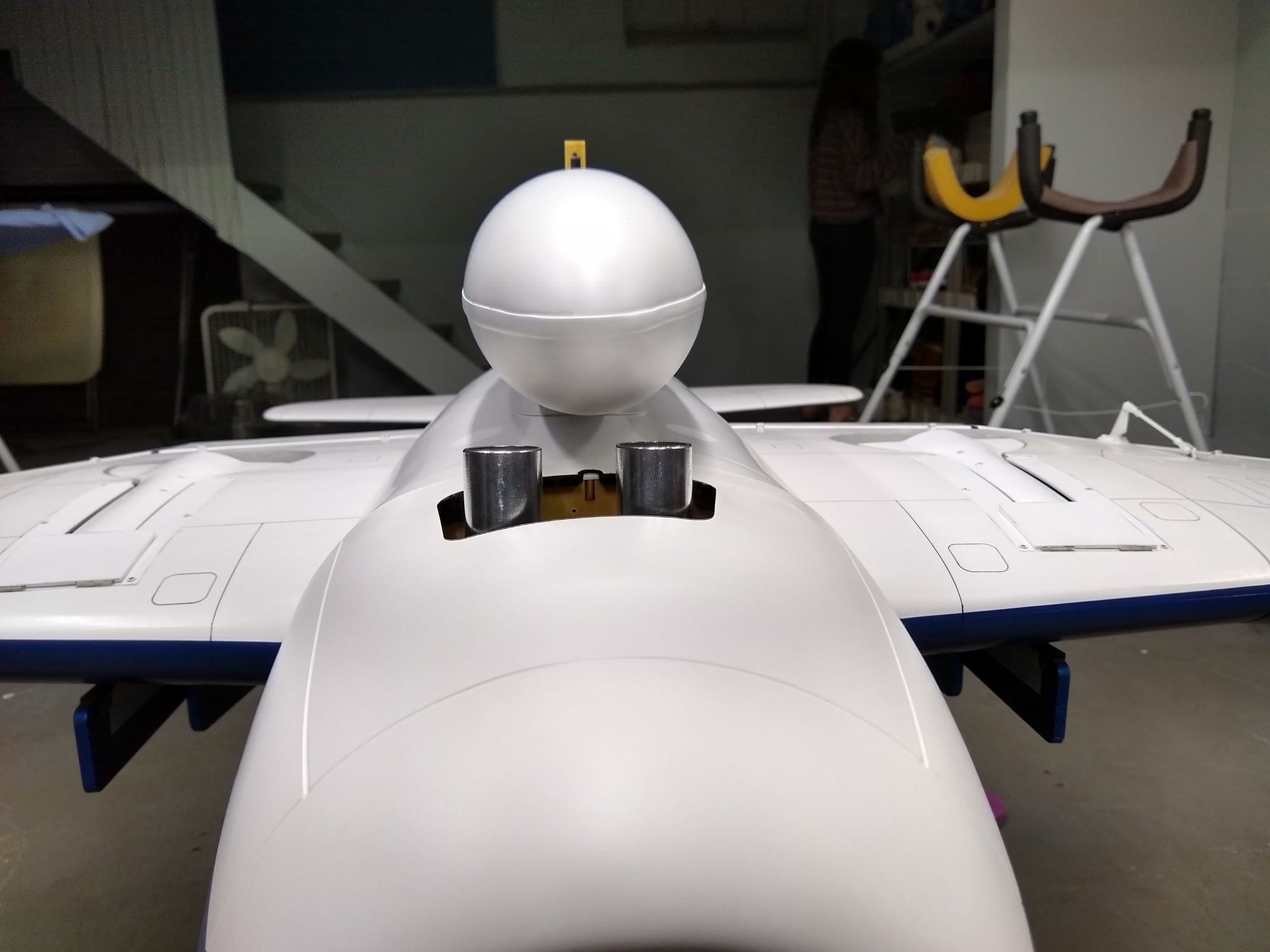
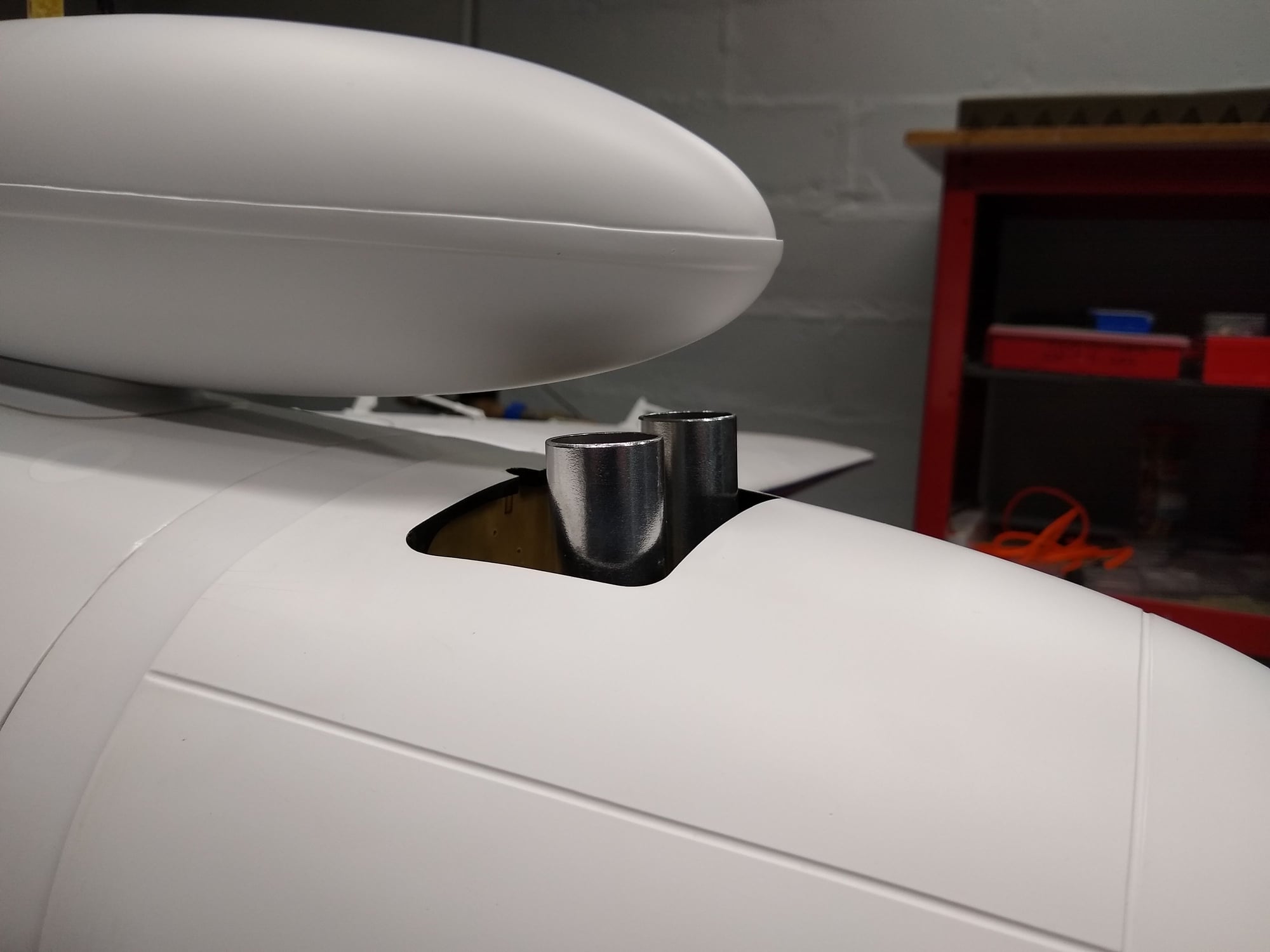
The drop tank does not change the CG at all. I am concerned for how close this is to the exhaust. I spent way too much time on that tank. I glassed the entire inside, reinforced the structure and completely primed an painted it. I fear it will get burned up by the exhaust and or hurt the performance of the engine. I can perhaps put some aluminum tape in that area. I use that inside of my turbine jets. I may have to plan to drop the tank early in the flight.

04-02-2020, 06:20 AM
#460

Thanks for posting your pics, looks great, interested to hear about your mods.
Question:
What C/G balancer are you using for your model?
Best regards
Randy
04-02-2020, 06:37 AM
#461
Hi RBean:
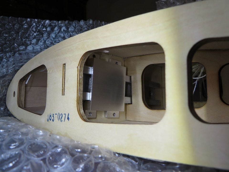
Thanks for posting the pics of the outer wing panel joiner method.
The 1/4-20 method will work fine.
I like the access point through the landing gear wheel well. I will look at keeping the fiberglass wheel well in place and use a 1/4-20 socket head bolt.
A 3/8" access hole in the side of the well should be enough to slide the bolt head through.
I'll keep you posted on the results.
Best regards
Randy
Last edited by cgcrc; 04-02-2020 at 06:39 AM.
04-05-2020, 10:54 AM
#463
My Feedback: (60)
Join Date: Dec 2001
Location: Litchfield Park,
AZ
Posts: 7,677
Likes: 0
Received 25 Likes
on
23 Posts
04-05-2020, 05:27 PM
#465
Hi RBean:
Thanks for posting the pics of the outer wing panel joiner method.
The 1/4-20 method will work fine.
I like the access point through the landing gear wheel well. I will look at keeping the fiberglass wheel well in place and use a 1/4-20 socket head bolt.
A 3/8" access hole in the side of the well should be enough to slide the bolt head through.
I'll keep you posted on the results.
Best regards
Randy
John
04-07-2020, 10:01 AM
#466
04-10-2020, 07:38 PM
#469
Hi John and RBean:
Thanks for posting your pics....agreed, nice alternative for the wing joining method.
As previously mentioned the RTC models can now fill in the access holes on the wing sheeting.
Randy
Thanks for posting your pics....agreed, nice alternative for the wing joining method.
As previously mentioned the RTC models can now fill in the access holes on the wing sheeting.
Randy
The following users liked this post:
CAPT John (04-10-2020)
The following users liked this post:
CAPT John (04-11-2020)
04-11-2020, 07:35 PM
#472
Hi Fellows
(I�m just finishing my present build and about to move onto the RTC Hellcat assembly)
Thanks to all who have posted suggestions, ideas and pics re the outer wing panel mounting process.
I like the idea of the 1/4-20 socket head bolt and blind nut option through the wheel well. It�s the easiest mod with a small hole in the fiberglass LG tub.
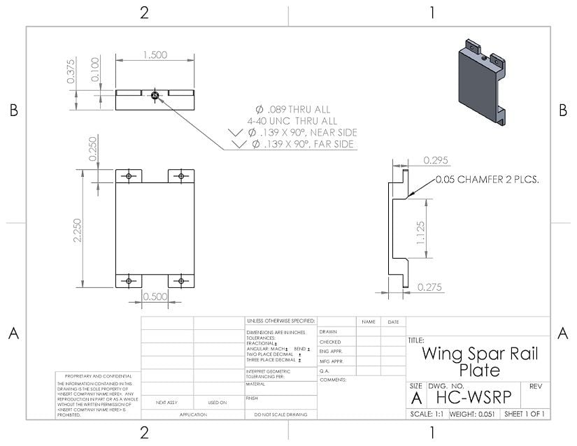
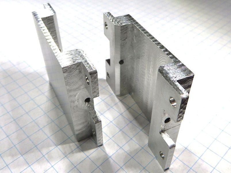
For those who have access to a milling machine, here is another option if you elect to use the existing top and bottom wing mounting method.
An aluminum cap that is machined, pre drilled, tapped and glued in place with JB Weld over the existing rail. It allows for a lot more material the 4-40 bolt will thread through both top and bottom.
Because it can�t be screwed into place against the spar the added tabs with holes provide further gluing surface.
The cap can be held in place with a clamp during the glue curing process.
Best regards
Randy
(I�m just finishing my present build and about to move onto the RTC Hellcat assembly)
Thanks to all who have posted suggestions, ideas and pics re the outer wing panel mounting process.
I like the idea of the 1/4-20 socket head bolt and blind nut option through the wheel well. It�s the easiest mod with a small hole in the fiberglass LG tub.
For those who have access to a milling machine, here is another option if you elect to use the existing top and bottom wing mounting method.
An aluminum cap that is machined, pre drilled, tapped and glued in place with JB Weld over the existing rail. It allows for a lot more material the 4-40 bolt will thread through both top and bottom.
Because it can�t be screwed into place against the spar the added tabs with holes provide further gluing surface.
The cap can be held in place with a clamp during the glue curing process.
Best regards
Randy
Last edited by cgcrc; 04-11-2020 at 07:38 PM.
The following users liked this post:
CAPT John (04-12-2020)
04-12-2020, 09:28 AM
#474

Which means the rtc will show discontinued once the warehouse runs out. Several parts are discontinued too. Man I hate how horizonhobby does business. �Sell a few and discontinue� should be their motto, hell maybe it is. Absolutely no loyalty to their customers.