Maj. Woody's Topflight Hellcat


 04-29-2020, 03:34 PM
#4
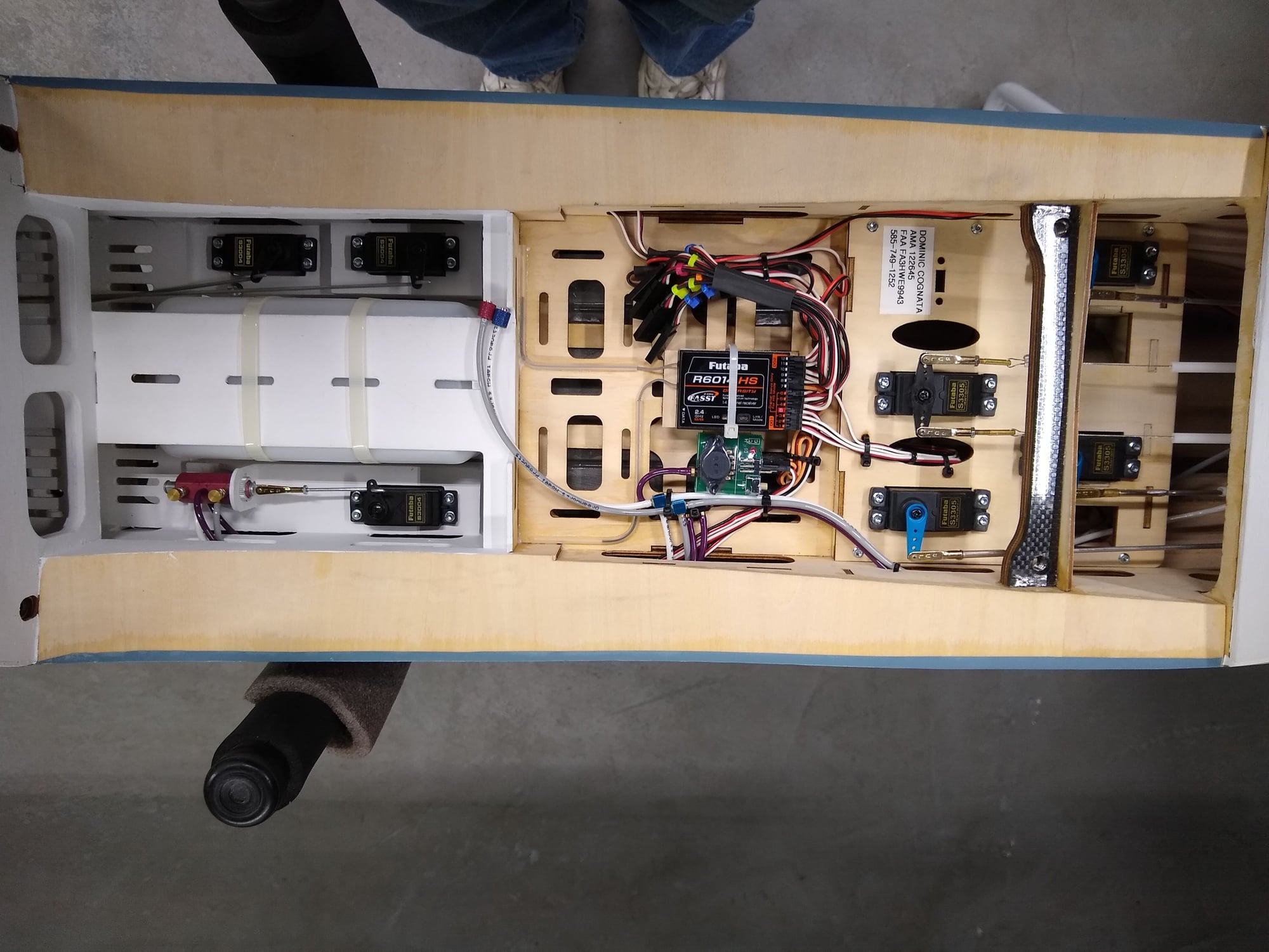
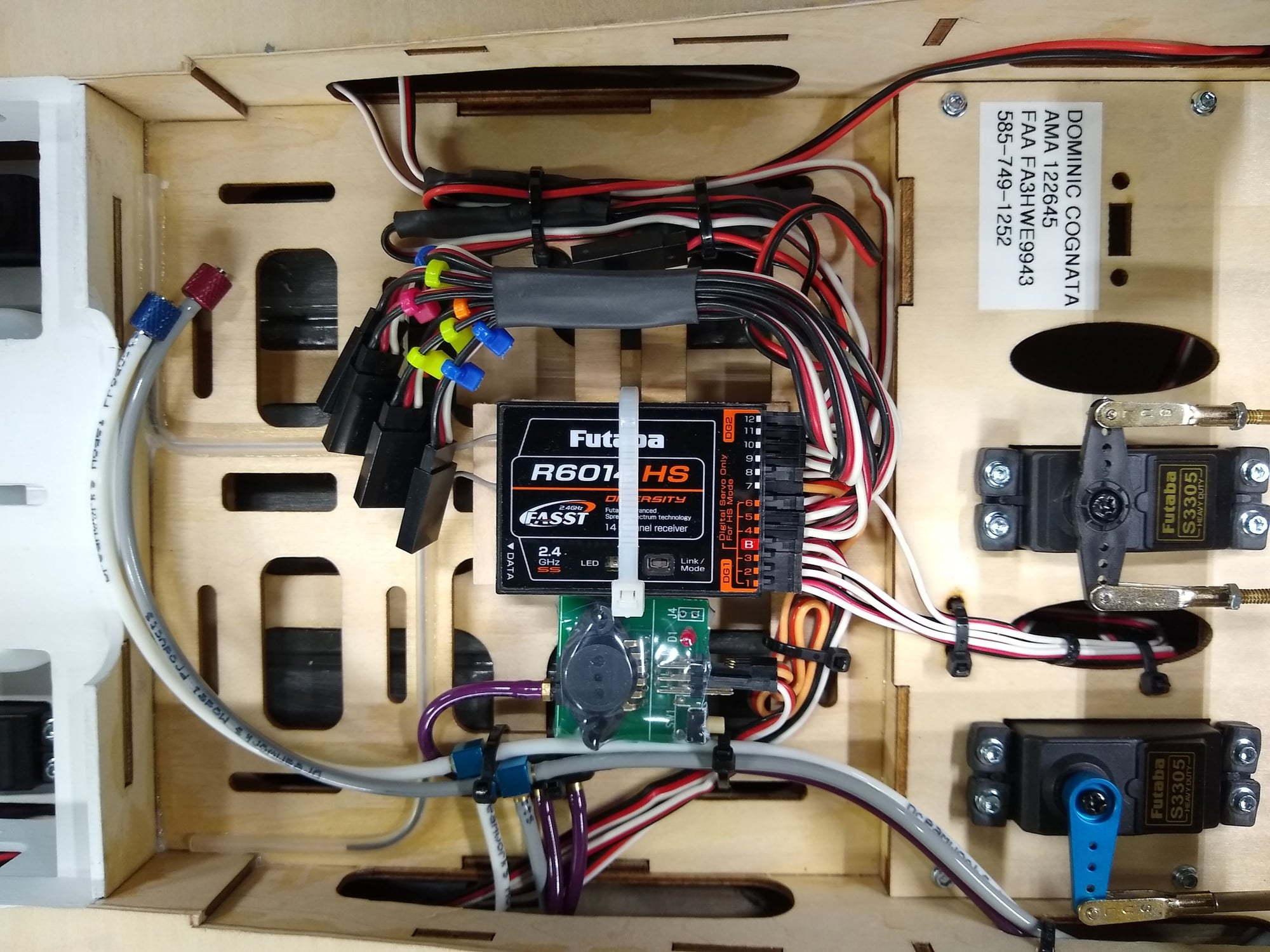
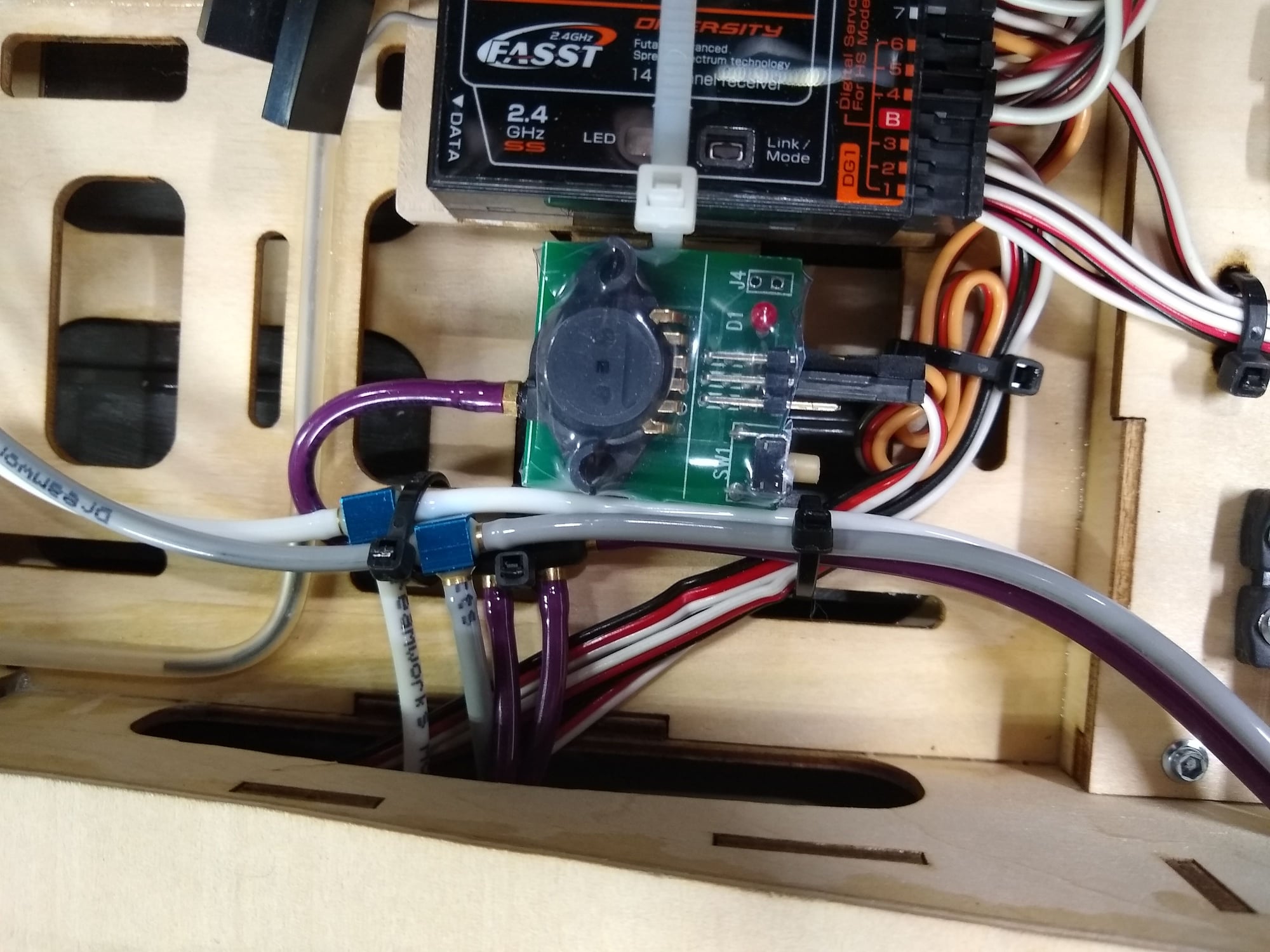
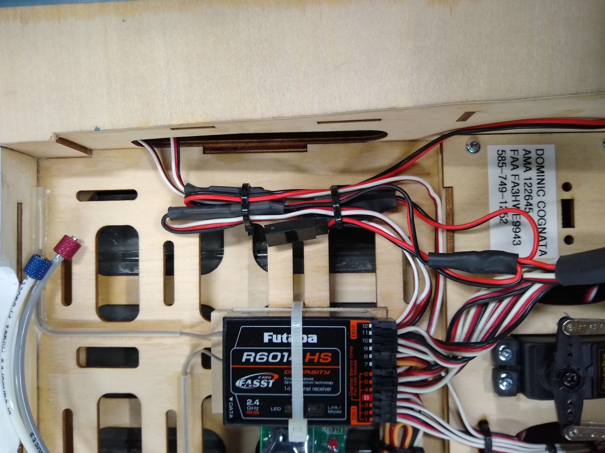
Here is a closer look. The Futaba receiver is mounted in a box lined with Dubro Foam Rubber. Antennas are routed through antenna tubes providing the proper orientation. Also shown is the Tamjets Gear Failsafe. I have all wires neatly routed and bundled to prevent any chaffing or interference with servos and such. All servo leads are color coded.
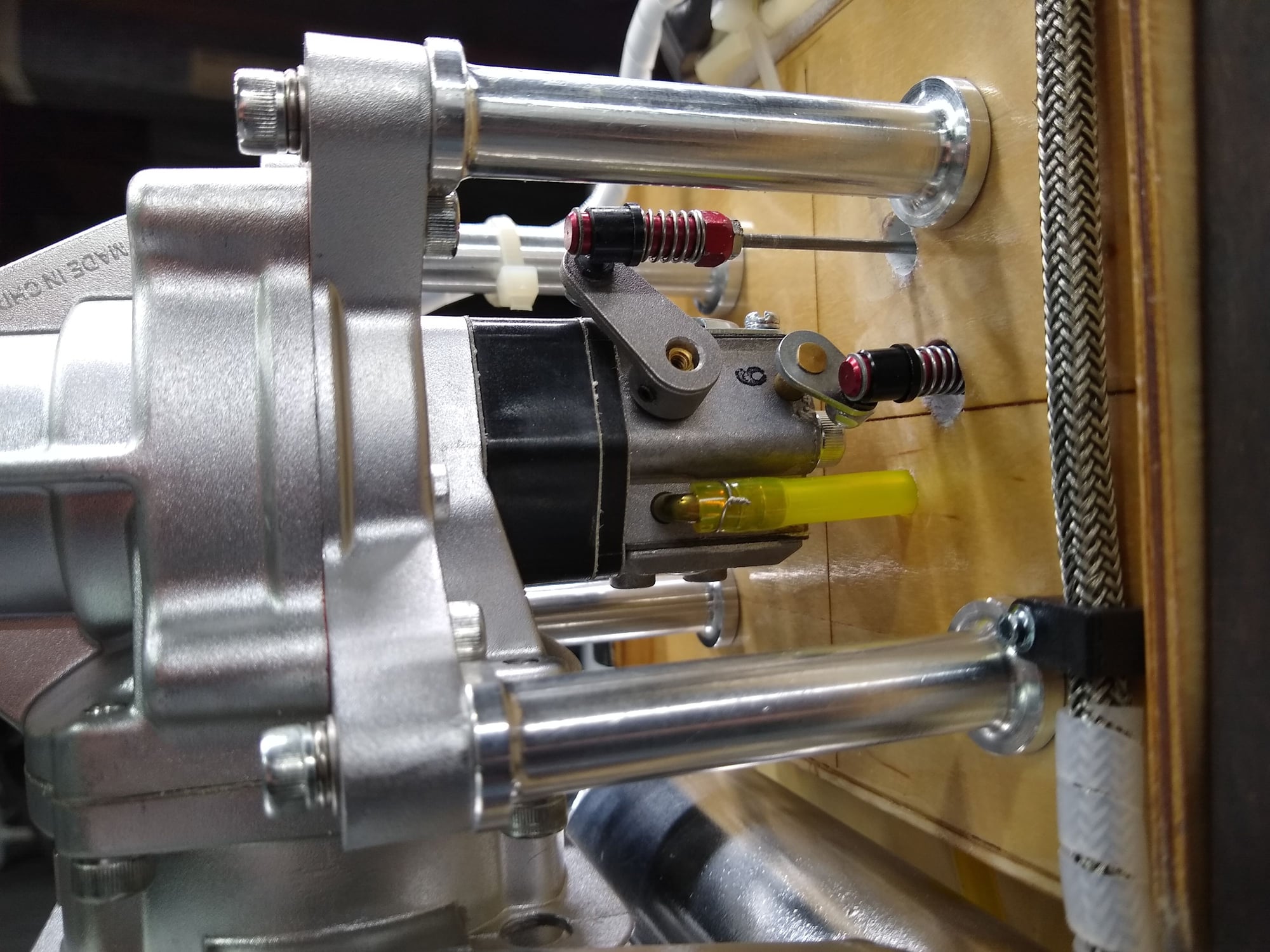
 04-29-2020, 03:43 PM
#7
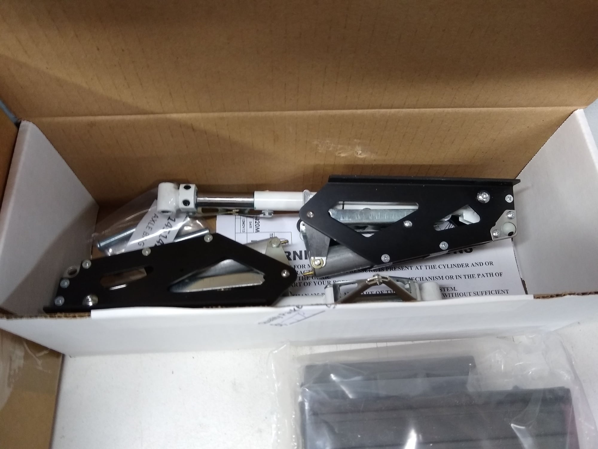
When I first bolted on the wing (I am using metal socket cap bolts and washers) I did not like the flexing and the sounds I was getting from the wing bolt mount. To fix this I epoxied on a Heavy Duty peice of Carbon Fiber Plate. I also added gussets of Goop around all the surrounding joints. This is rock solid now!
04-29-2020, 03:50 PM
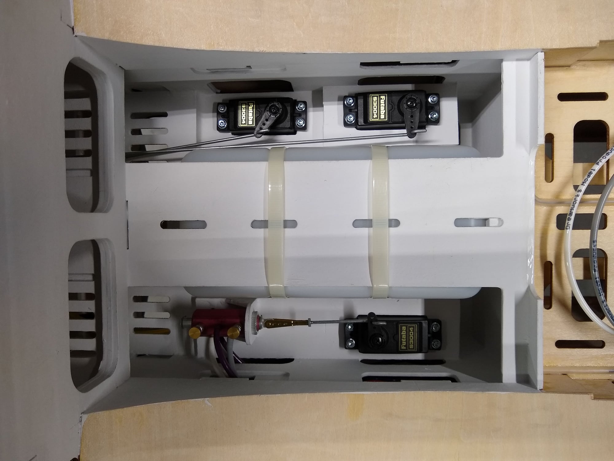
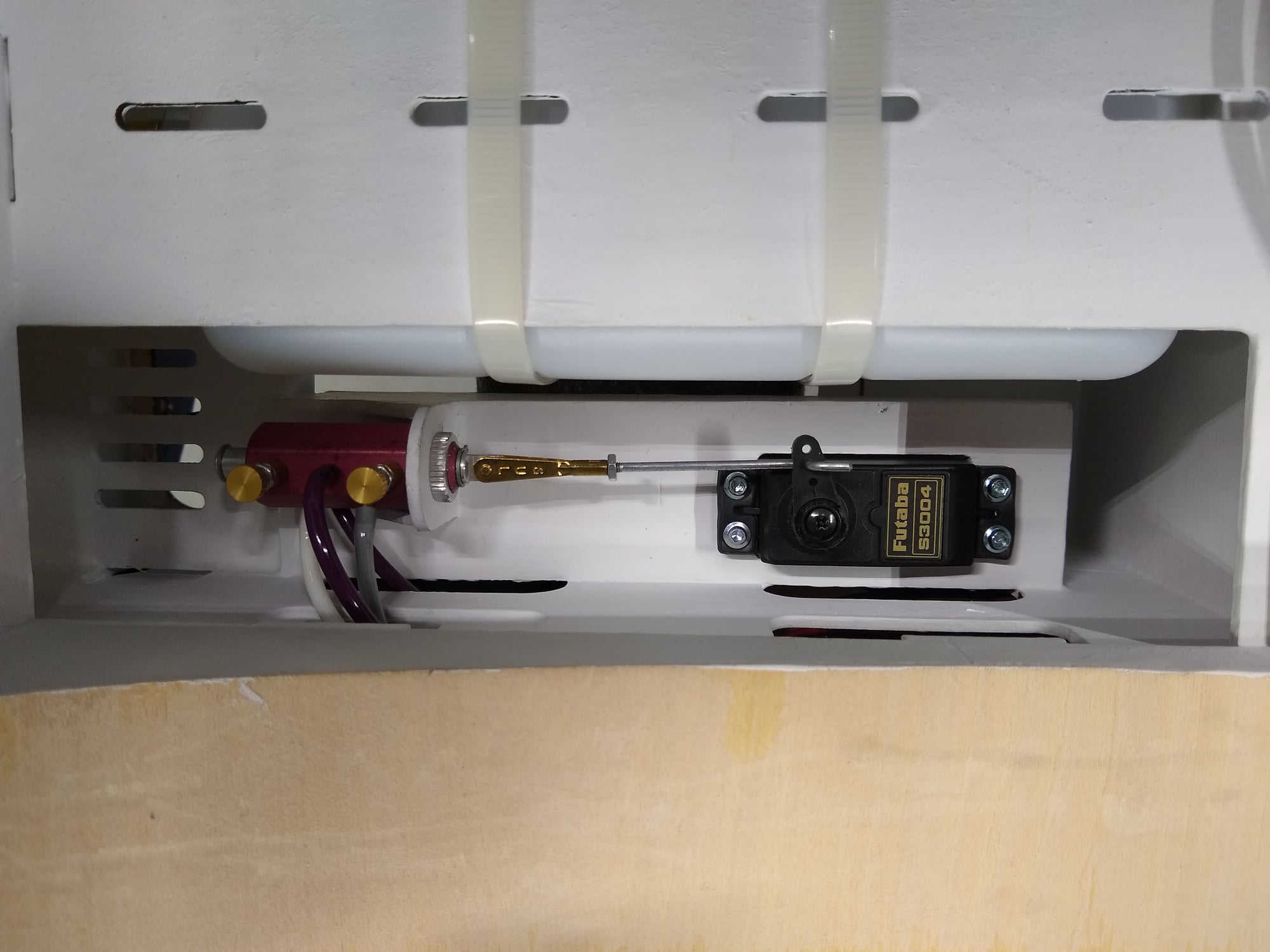
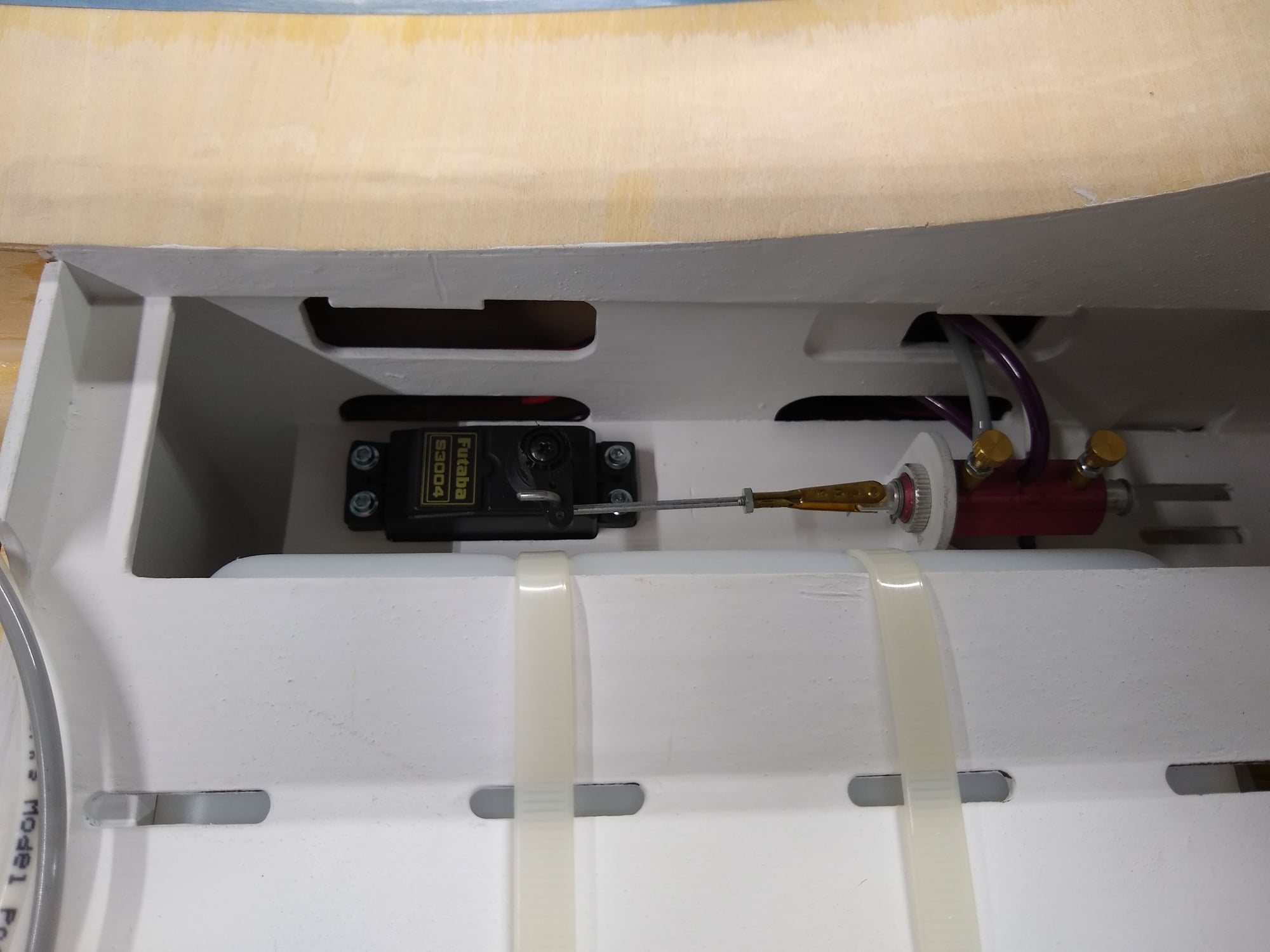
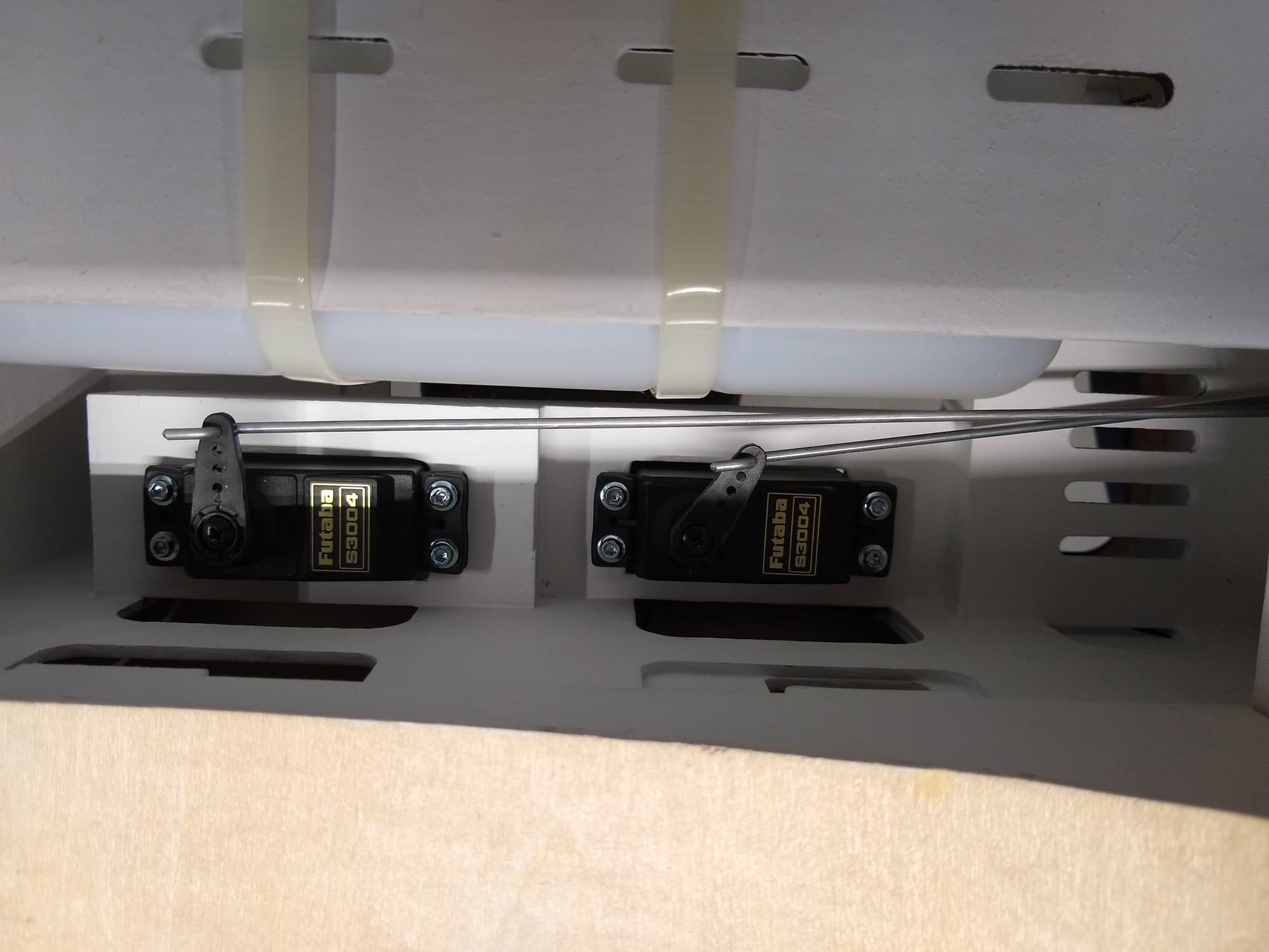
#8
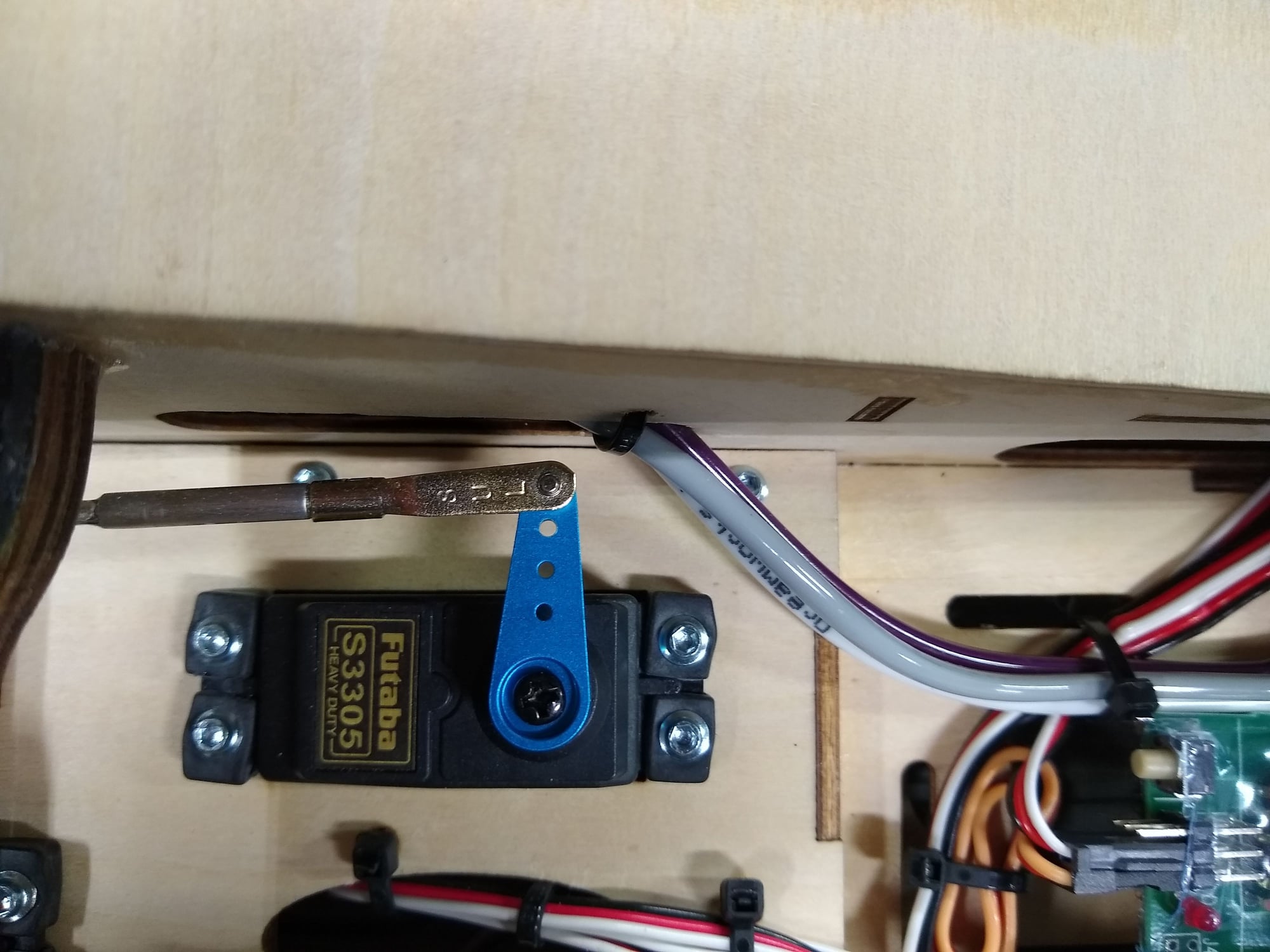
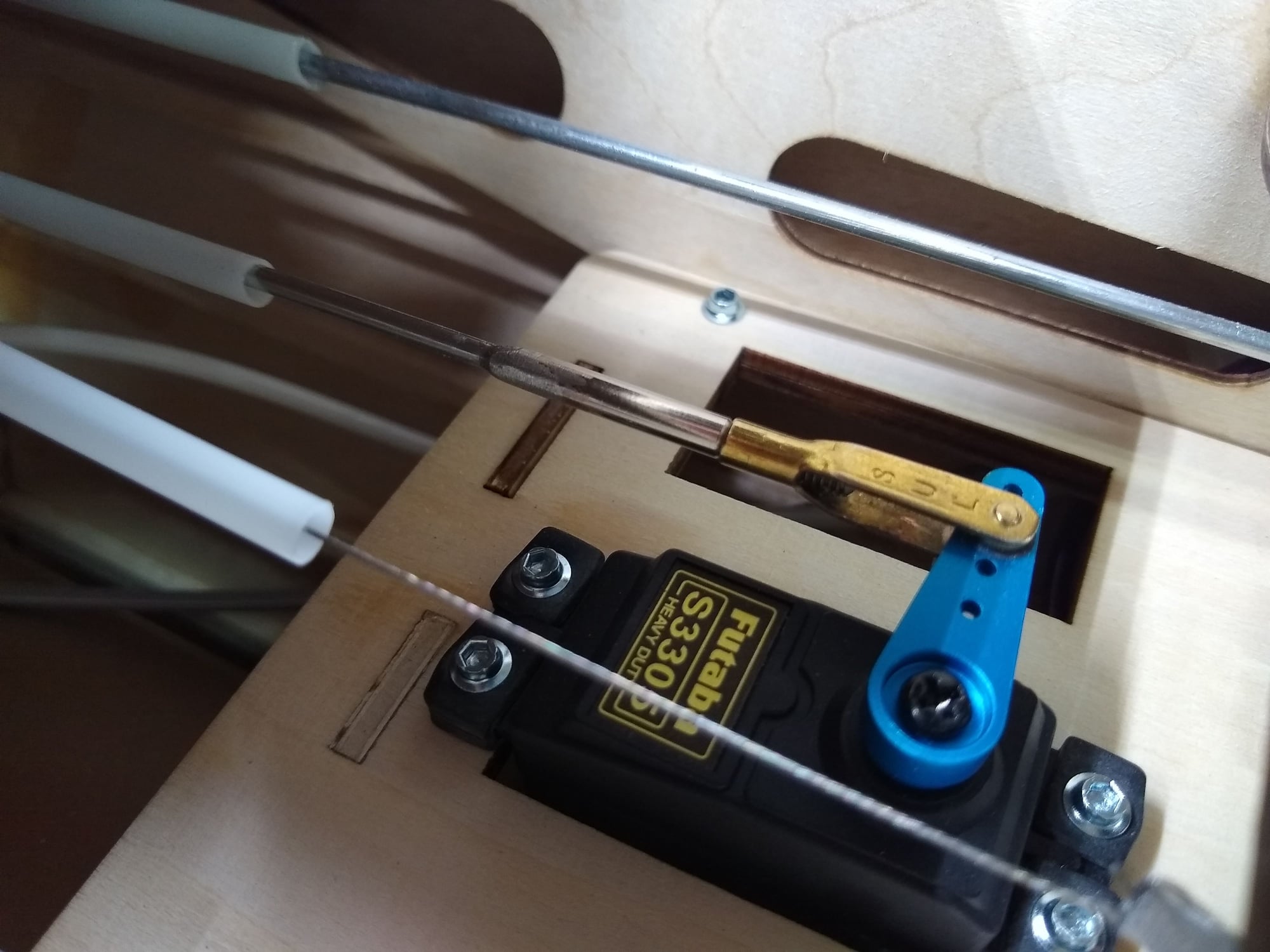
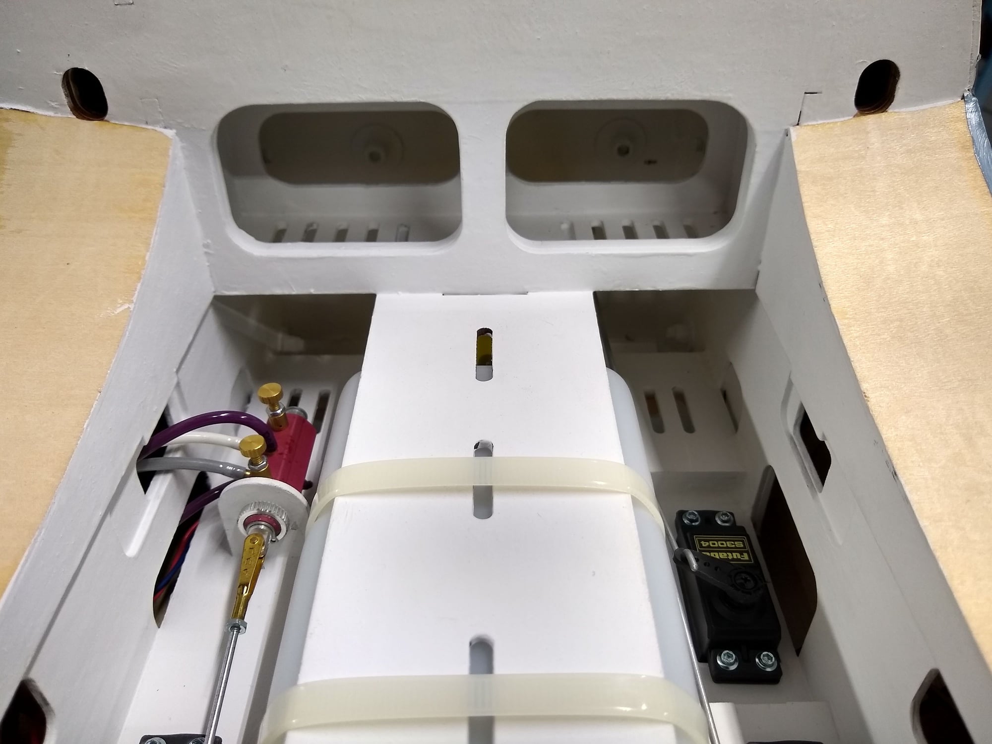
Here is a closer look at my retract, throttle and Choke servos. Note I used 4-40 rods in place of the provided nyrod. From this bay forward everything has been painted with fuel proof paint I like how it looks and it provides a degree of protection if the fuel tank leaks. You will see more of this later but I modified the battery tray / fuel tank mounting arrangement so that I could have access to the top hatch for my batteries, switches and fueling operations.
Last edited by MaJ. Woody; 04-29-2020 at 04:50 PM.
04-29-2020, 04:04 PM
#9
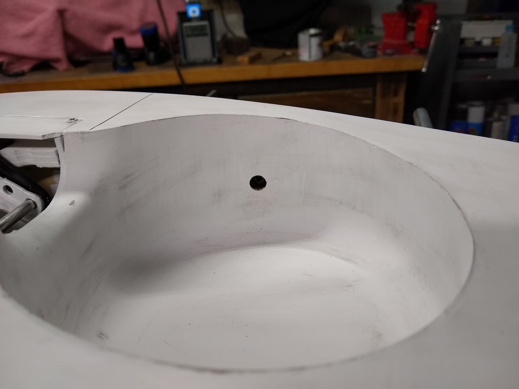
The Top hatch comes completely covered over from the factory. That sucks! So that I did not have any gaps or ugly seams, when I cut the covering to remove the hatch, I actually cut the covering above the hatch / fuse joint and from the hatch itself. I then needed to carefully pull the hatch out and this left excess covering that I was then able to wrap the ledge of the fuse surface with. Of course I needed to strip the remaining covering from the actual hatch and completely recover the hatch. Lots of work but no gaps or seams!
 04-29-2020, 04:16 PM
#12
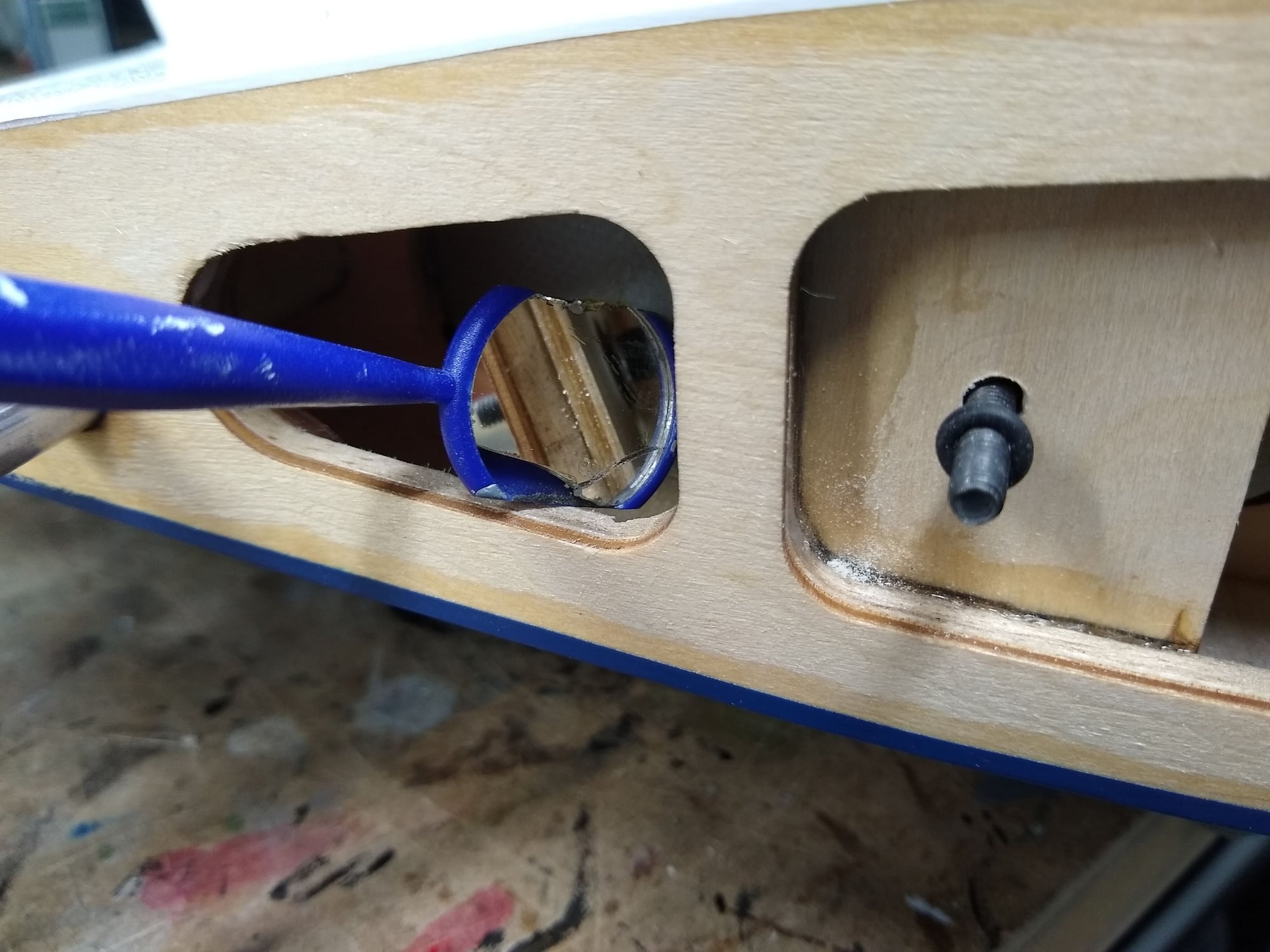
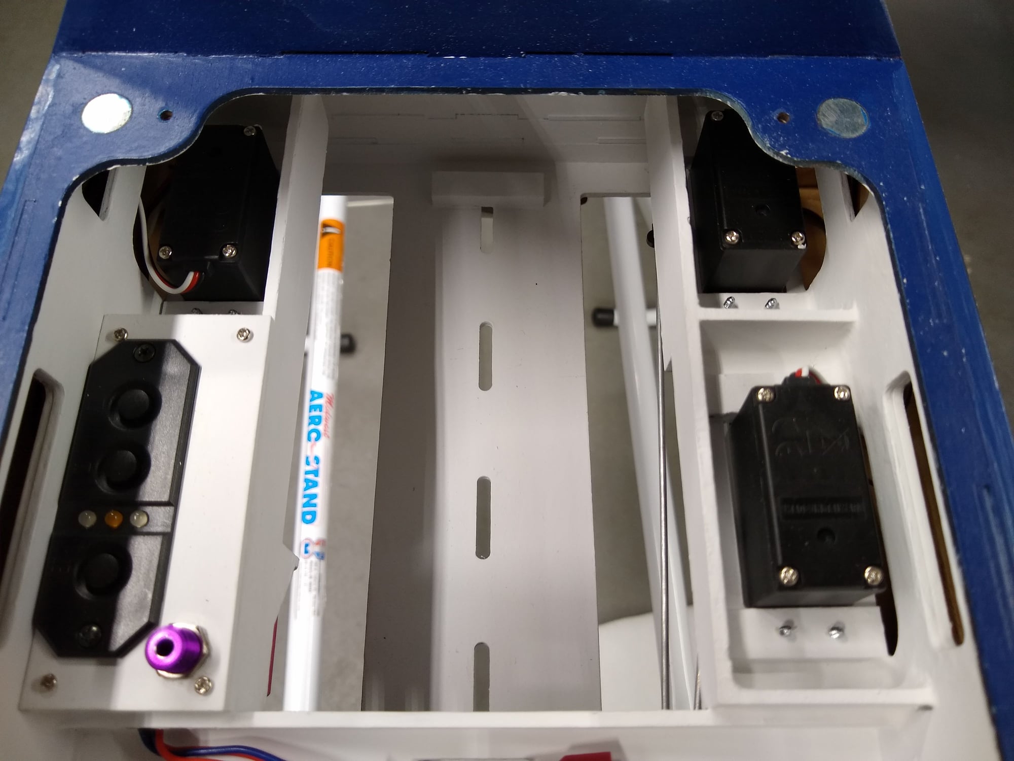
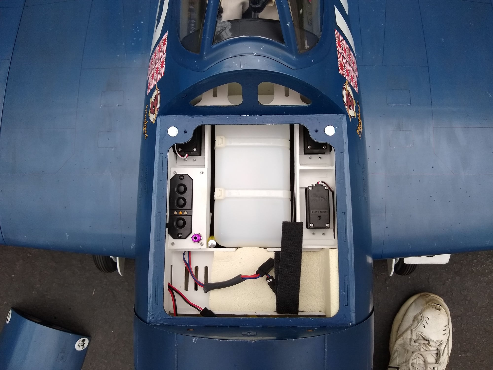
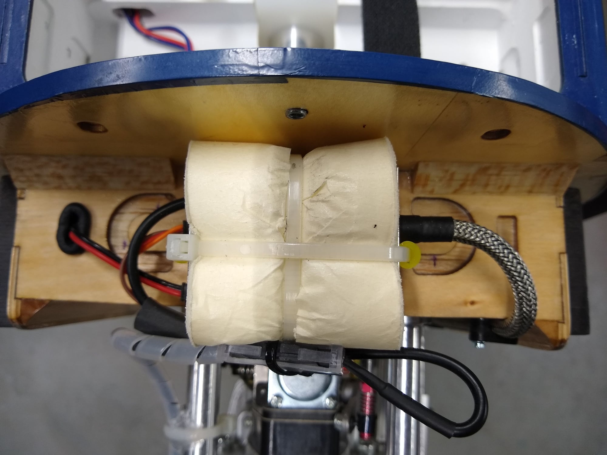
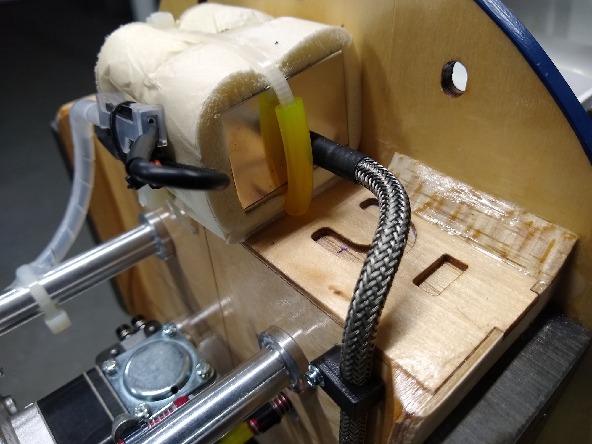
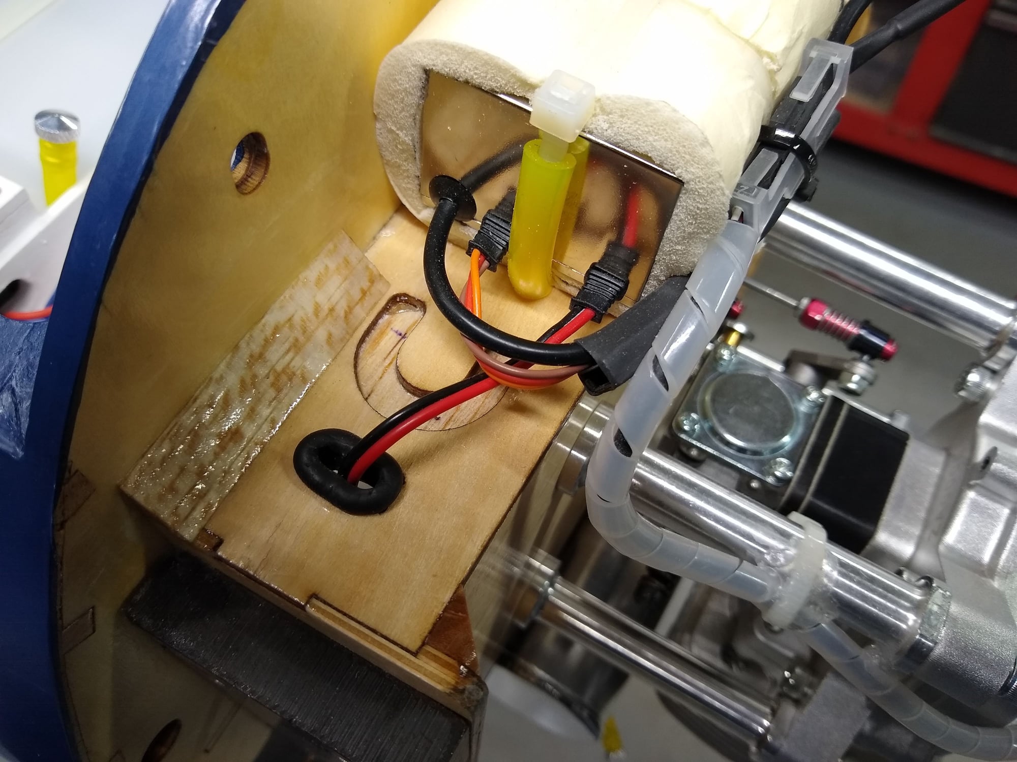
Here is a closer look at my battery tray. You will notice that I cut slots for my Velcro strap well inside the edge of the box. The reason for this is that when the strap is pulled tight, it will pull the batteries away from the sides to reduce vibration. The battery packs, two Thunder Power 2S RX Lipos and one 2S Ignition lipo sit on 1/2" Dubro Foam Rubber. The Power Box Sensor Switch is actually two electronic switches in one and knocks the voltage of the Lipos down from 7.4 to 6 volts.
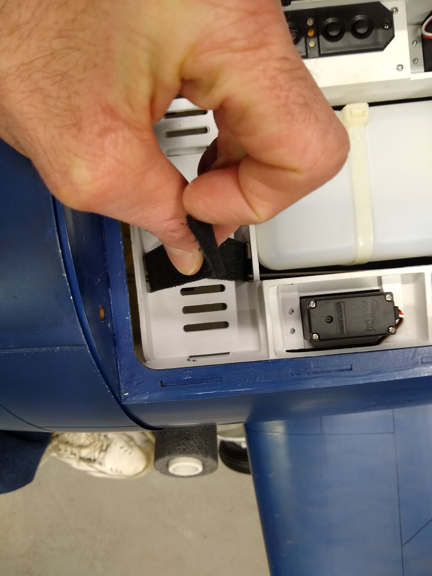
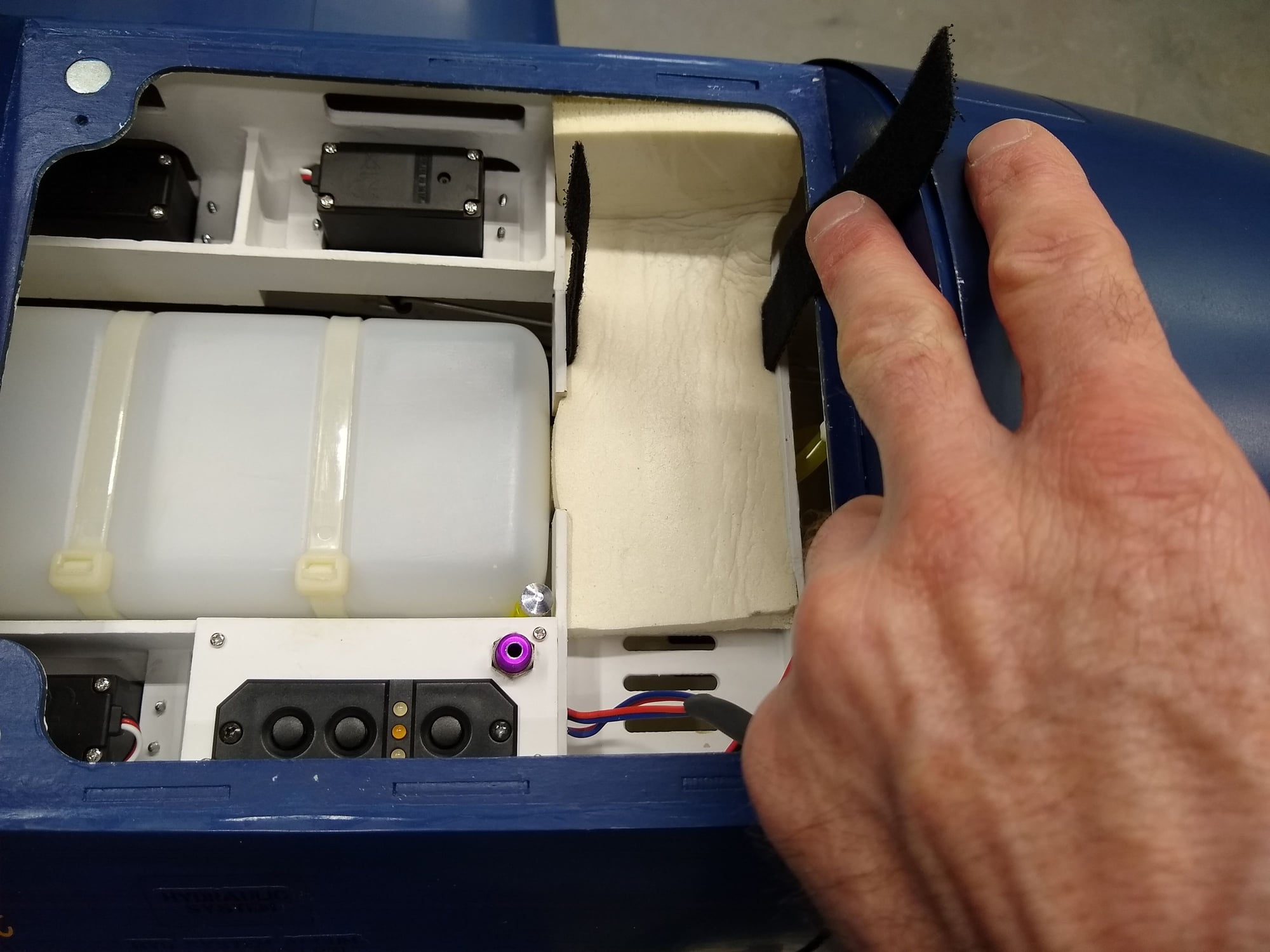
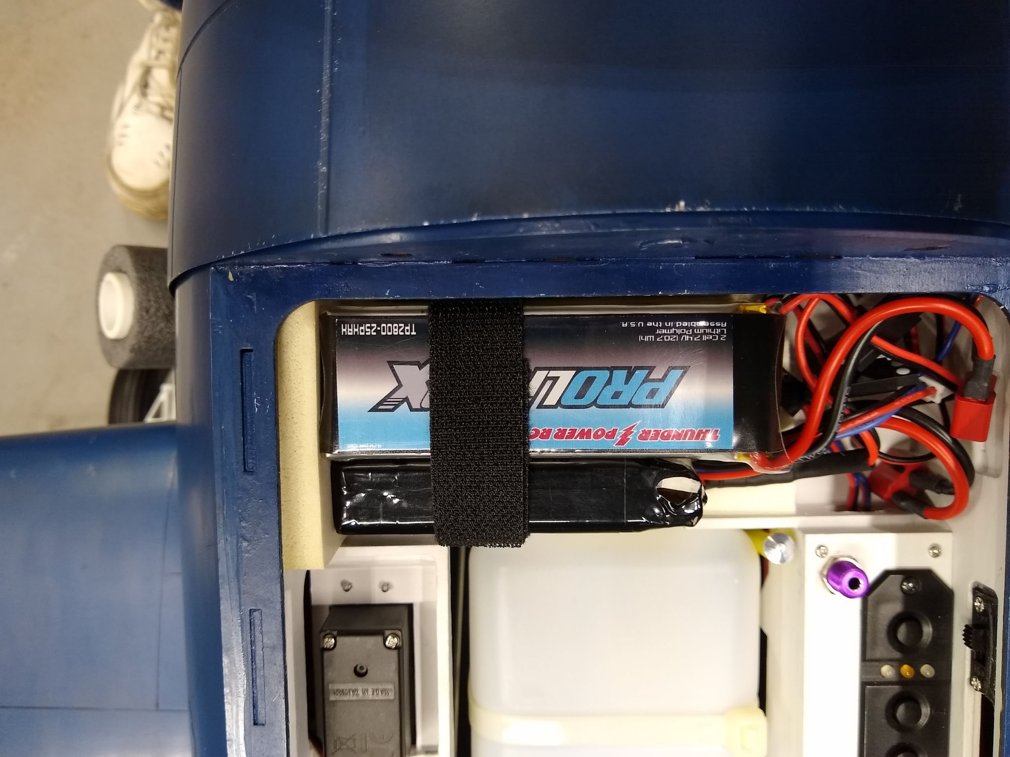
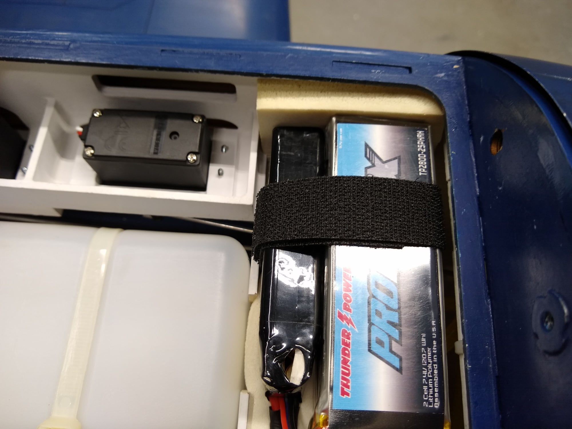
Last edited by MaJ. Woody; 04-29-2020 at 04:53 PM.

 04-30-2020, 02:41 AM
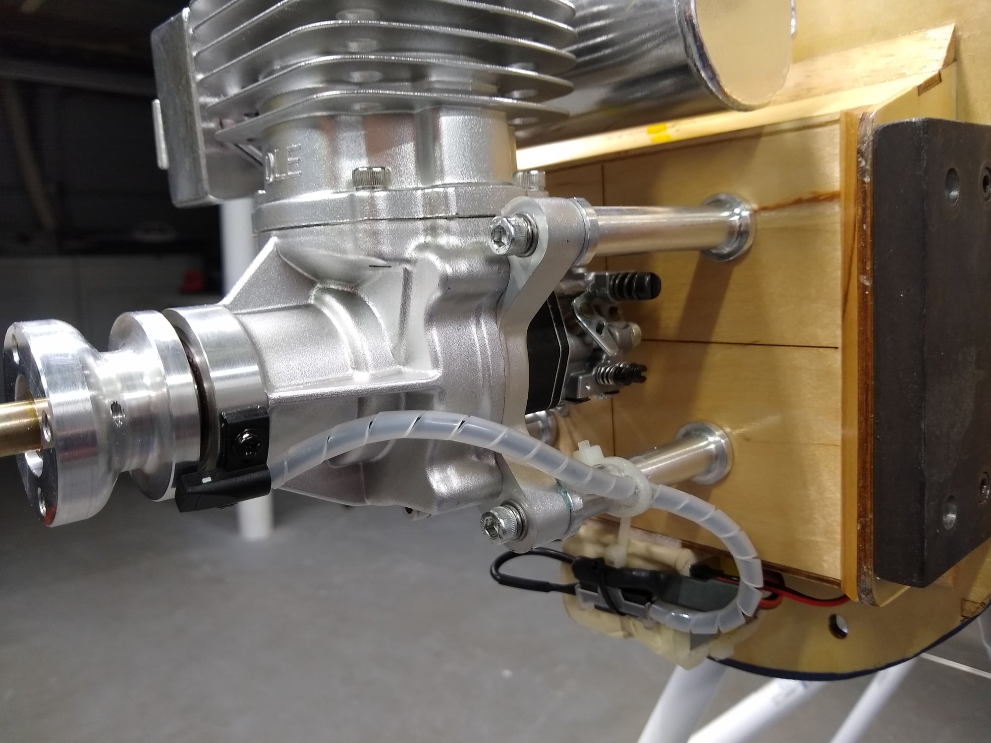
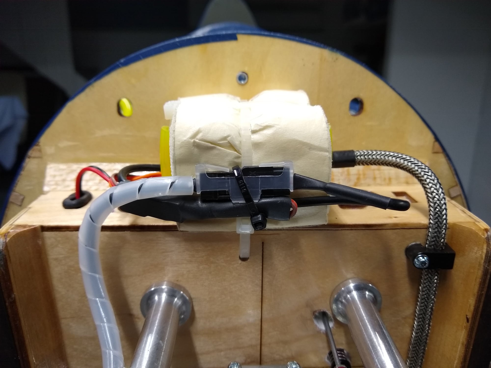
#16
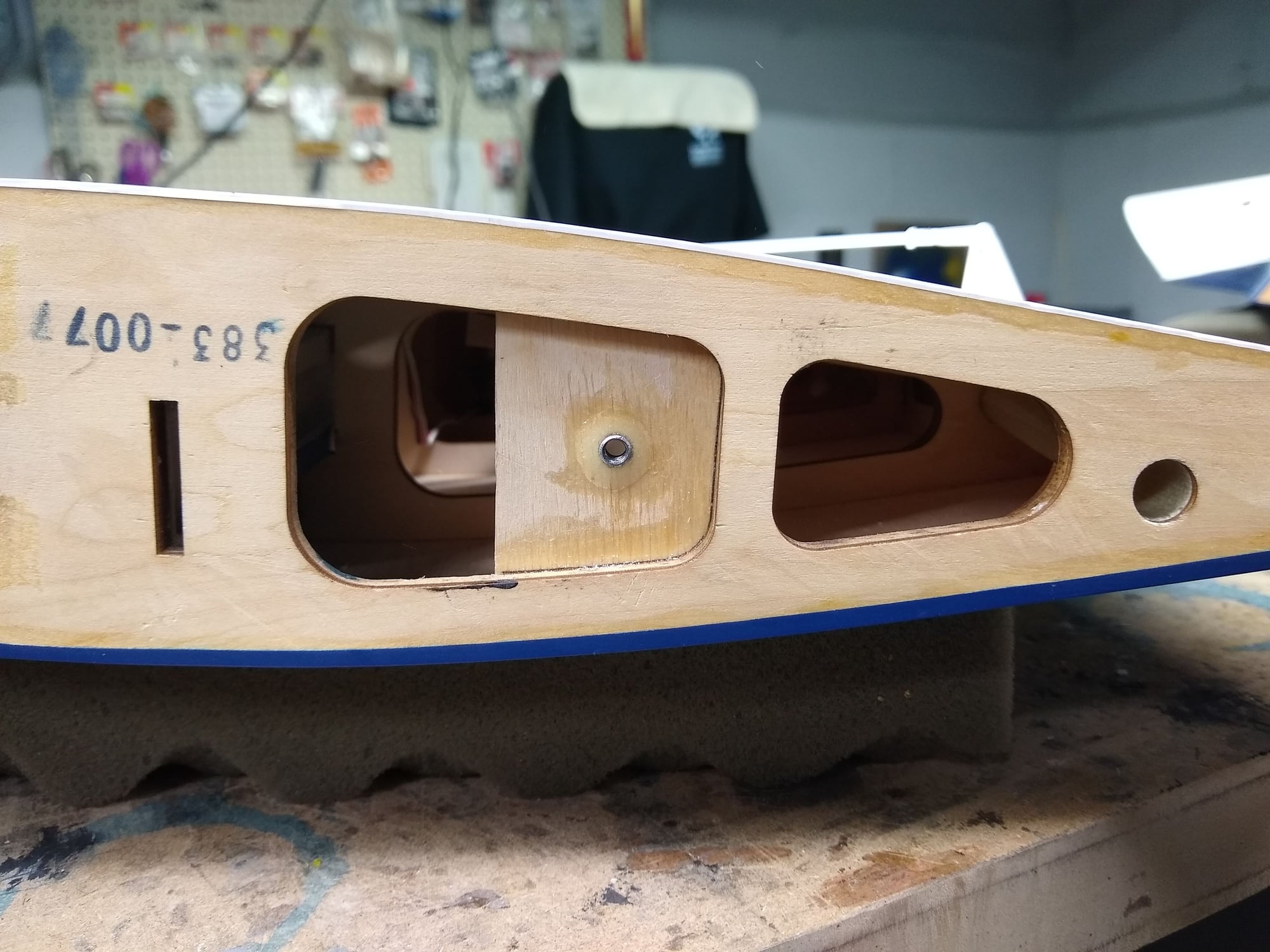
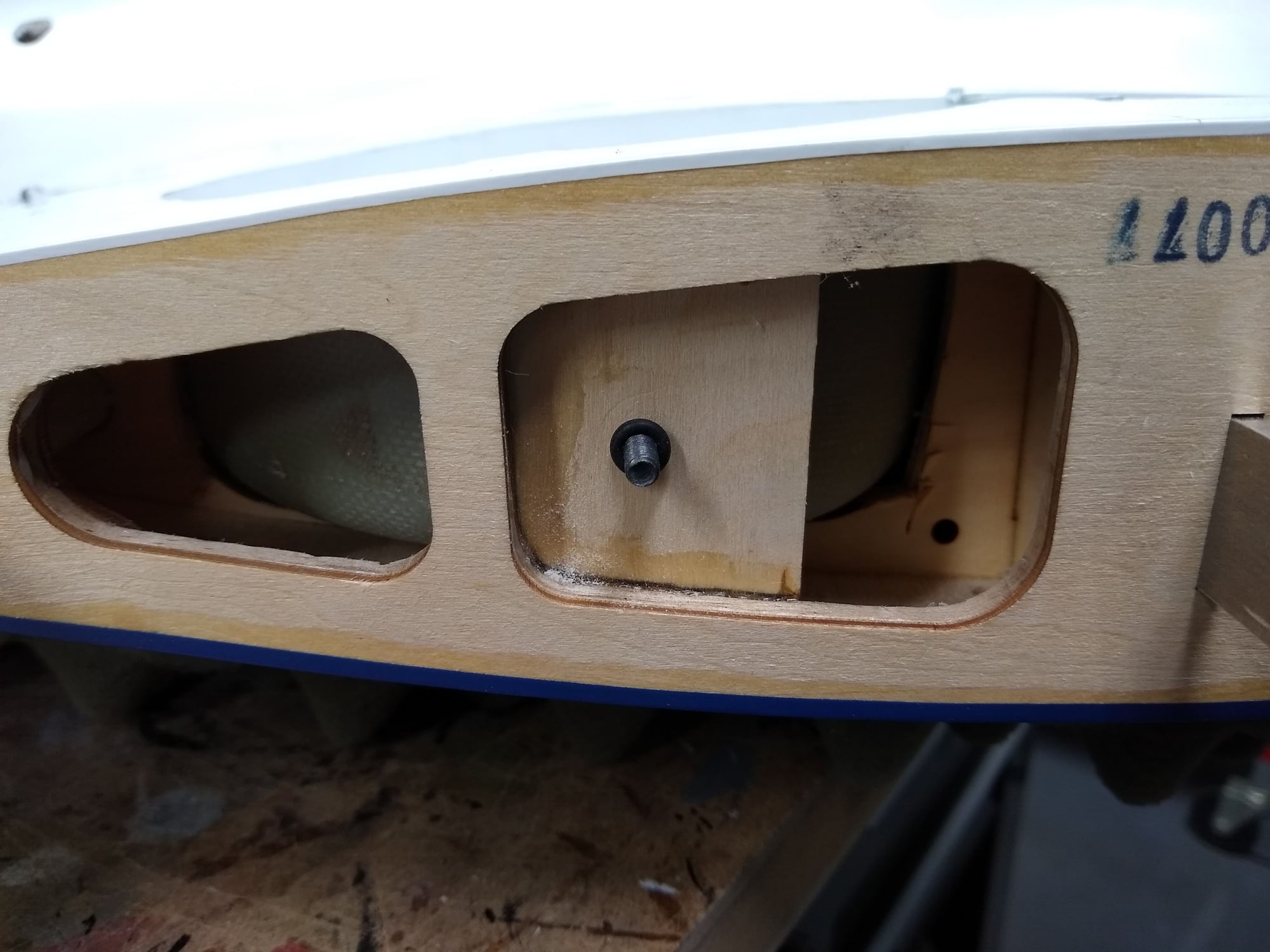
Here is how the ignition module is mounted. I glued in balsa sheeting from the inside of the firewall to close off the cutouts. Next I drilled holes for a zip tie. The zip tie holds the ignition in place and I added some fuel line over the zip tie to prevent chaffing. I used a grommet where the battery wire passes through the fuse. Also of note is the additional triangle stock I added to the upper and lower engine box.
 04-30-2020, 02:47 AM
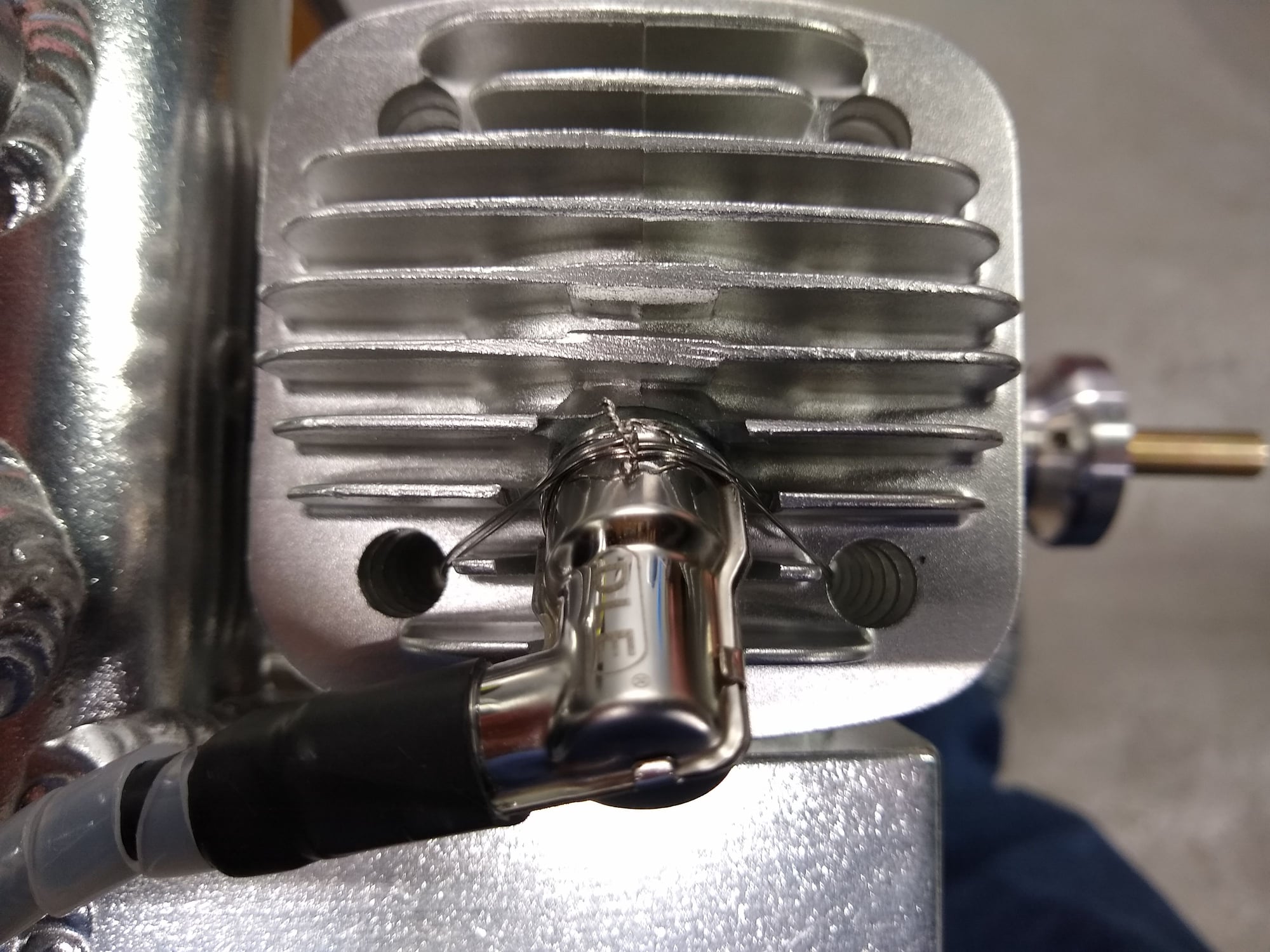
#18
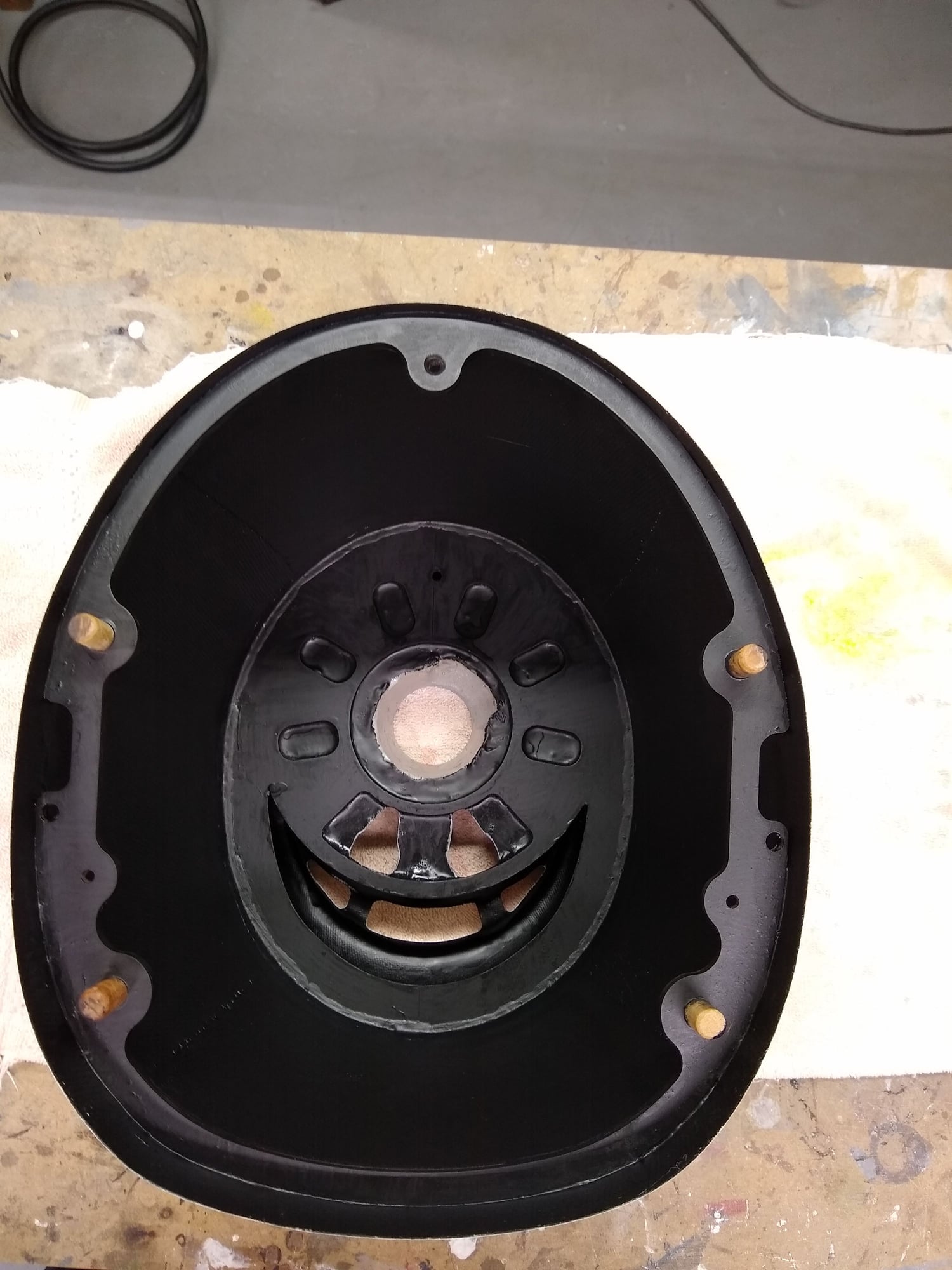
Since my spark plug cap will be hidden inside the cowl, I wanted to be sure the cap did not come off (I have had that happen before and dead sticks are never fun) so I safety wired it. This is accomplished by first applying the safety wire to the base of the cap tight against the wire ring, twisting it tight, then run the wires through the holes in the cooling fins till they meet and then twist them together. The cap does not budge!
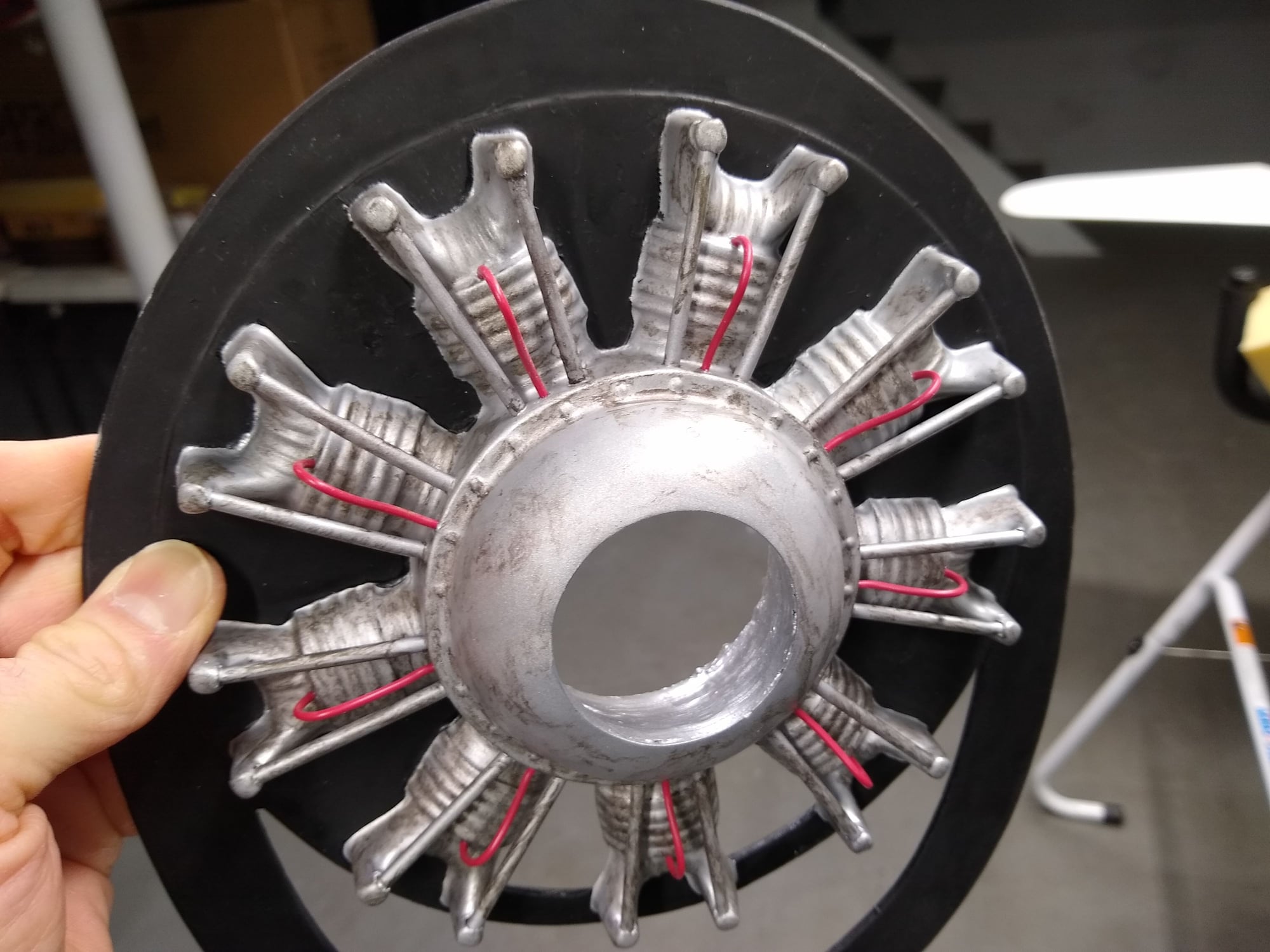
 04-30-2020, 03:00 AM
#21
I did not get a picture of it but the dummy radial engine was completely filled with West Systems Epoxy. This includes the cylinders as well as the engine case. I later needed to Dremel out the opening so the crank shaft and thrust washer could pass through. I wanted to add nose weight as well as be sure the thin plastic dummy engine did not crack. The dummy engine is glued to the bulkhead and the bulkhead is glued in place with CA. A bead of goop secures the entire bulkhead on both sides. I painted it black inside as I hate looking at bare fiberglass.