IA-58H Pucara Fenix Custom Plan and Build
 11-01-2023, 07:50 PM
#51
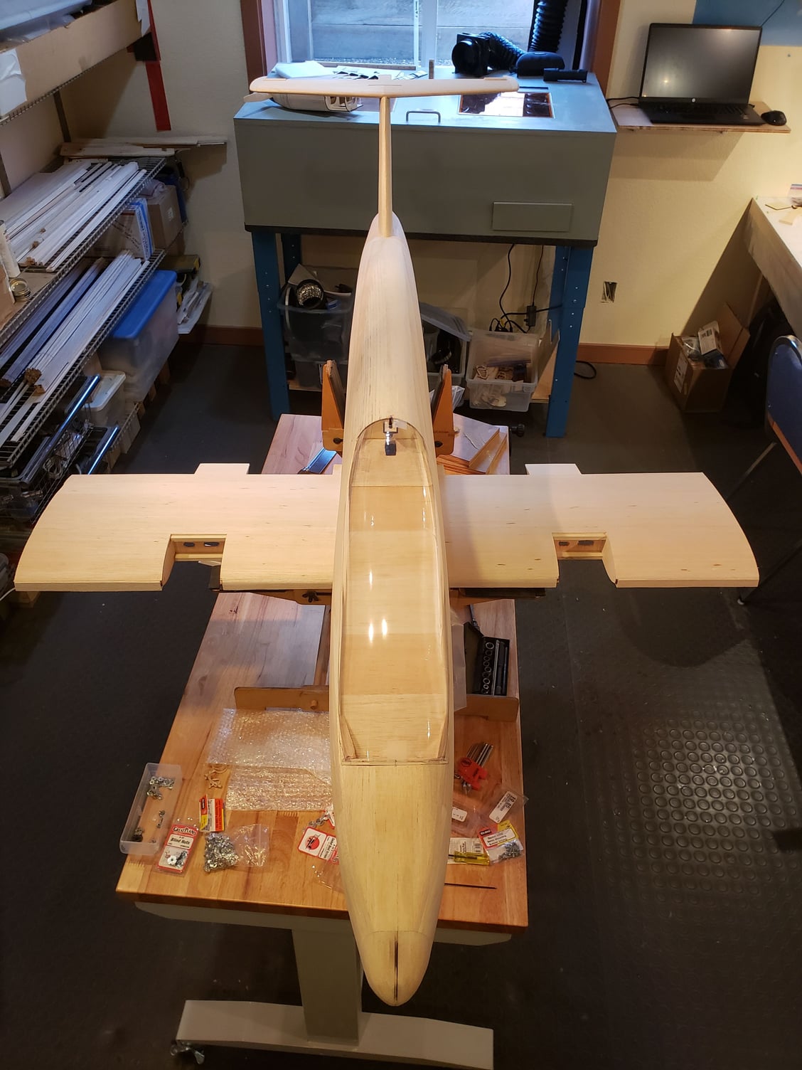
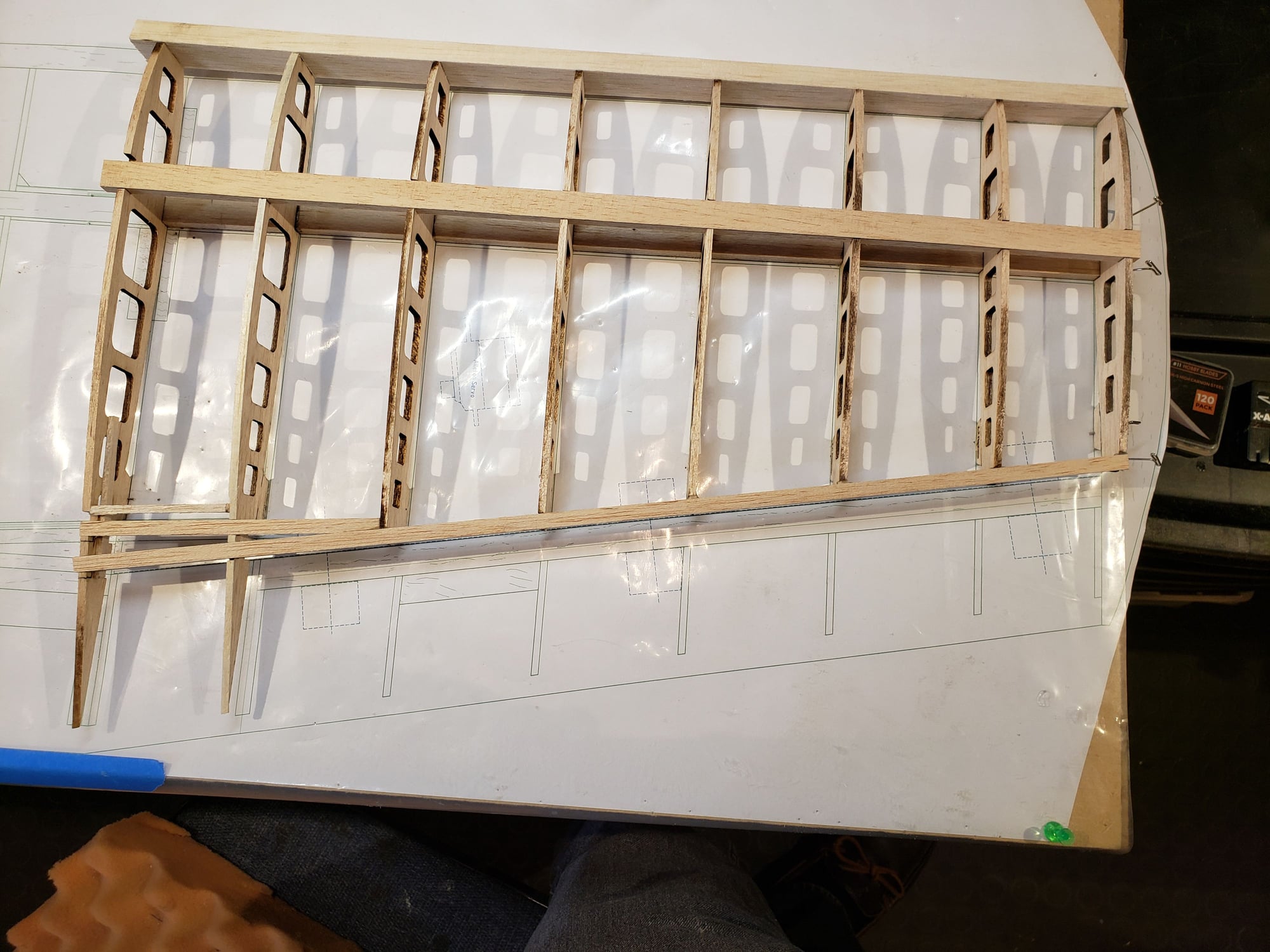
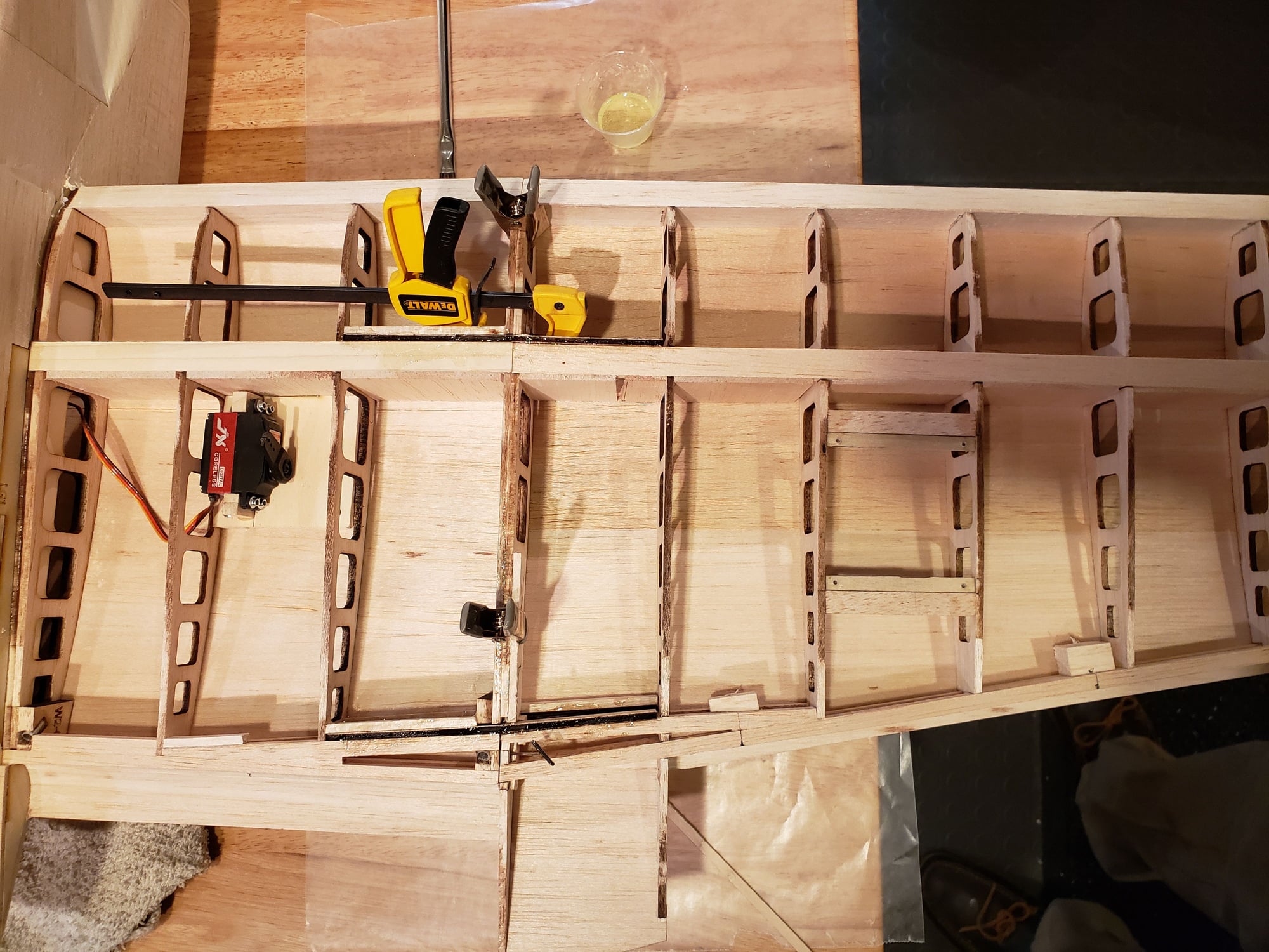
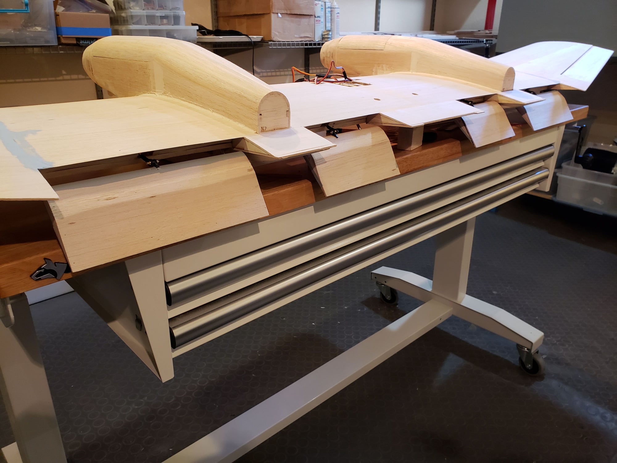
Completing the wing to the point that it can be lifted off the board ...
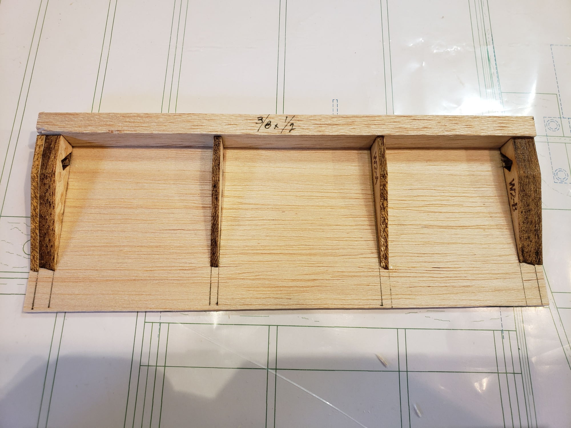
- add leading edge
- add rear spar
- add sheeting
The leading edge is added in 3 sections. The center one has 1/4" lite ply doublers to support the wing dowl pins.
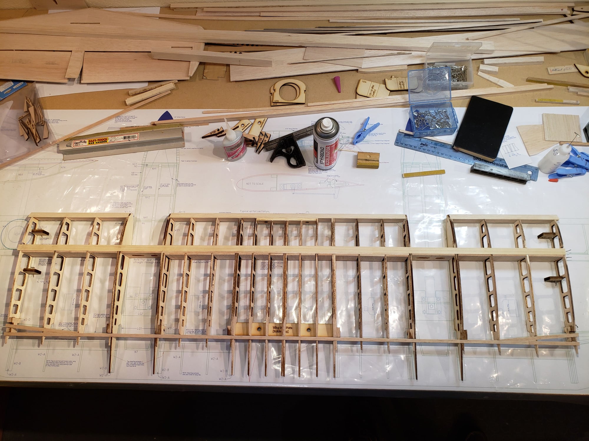
The rear spar is 1/4" sq stock. You can see in the picture that there is a "Y" in the spar at the last 2 ribs. The upper part will align with the rear spar in the outter wing panels and there will be a ply joiner to splice the joint.
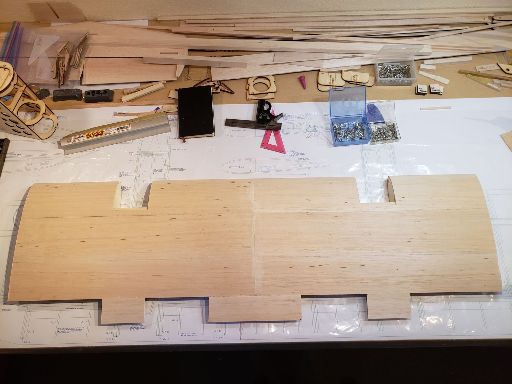
In the last pic you can see the sheeting (3/32") with cutouts for the flaps and nacelles.
- add leading edge
- add rear spar
- add sheeting
The leading edge is added in 3 sections. The center one has 1/4" lite ply doublers to support the wing dowl pins.
The rear spar is 1/4" sq stock. You can see in the picture that there is a "Y" in the spar at the last 2 ribs. The upper part will align with the rear spar in the outter wing panels and there will be a ply joiner to splice the joint.
In the last pic you can see the sheeting (3/32") with cutouts for the flaps and nacelles.

 11-01-2023, 07:56 PM
#53
I've installed the 1/4" wing dowels. Sanded the top half the the leading edge. Put 1/4-20 blind nuts in the fuse. I mounted the wing and it is perfectly square to the tail and perpendicular to the fuse centerline!
11-07-2023, 02:47 PM
#54
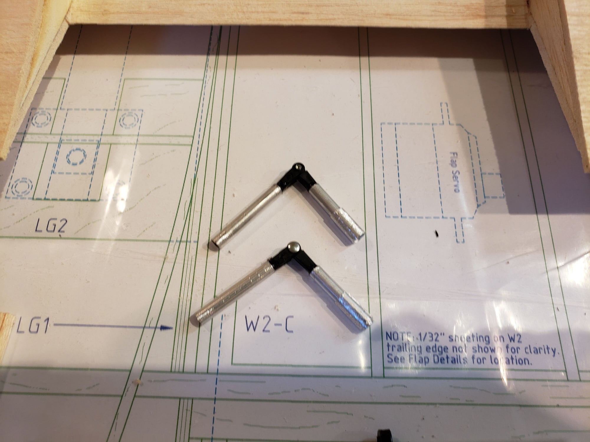
Making a slotted flap isn't terribly hard, but it's certainly a lot more work than setting up a plain flap because of the fact that the hinge line is outside the wing. There are a couple ways to set up the hinge. I'm using Robart pin hinges, so they need to be set at some angle as they don't close like a pair of scissors. Here's the design.
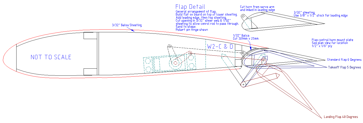
Note that 40 degrees down is the max deflection. A slotted flap develops it's greatest lift at that angle. And it develops more lift than a plain flap as you can see in this graph mapping the coefficient of lift against the angle of attack.
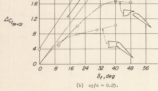
Note that 40 degrees down is the max deflection. A slotted flap develops it's greatest lift at that angle. And it develops more lift than a plain flap as you can see in this graph mapping the coefficient of lift against the angle of attack.
 11-07-2023, 02:52 PM
#56
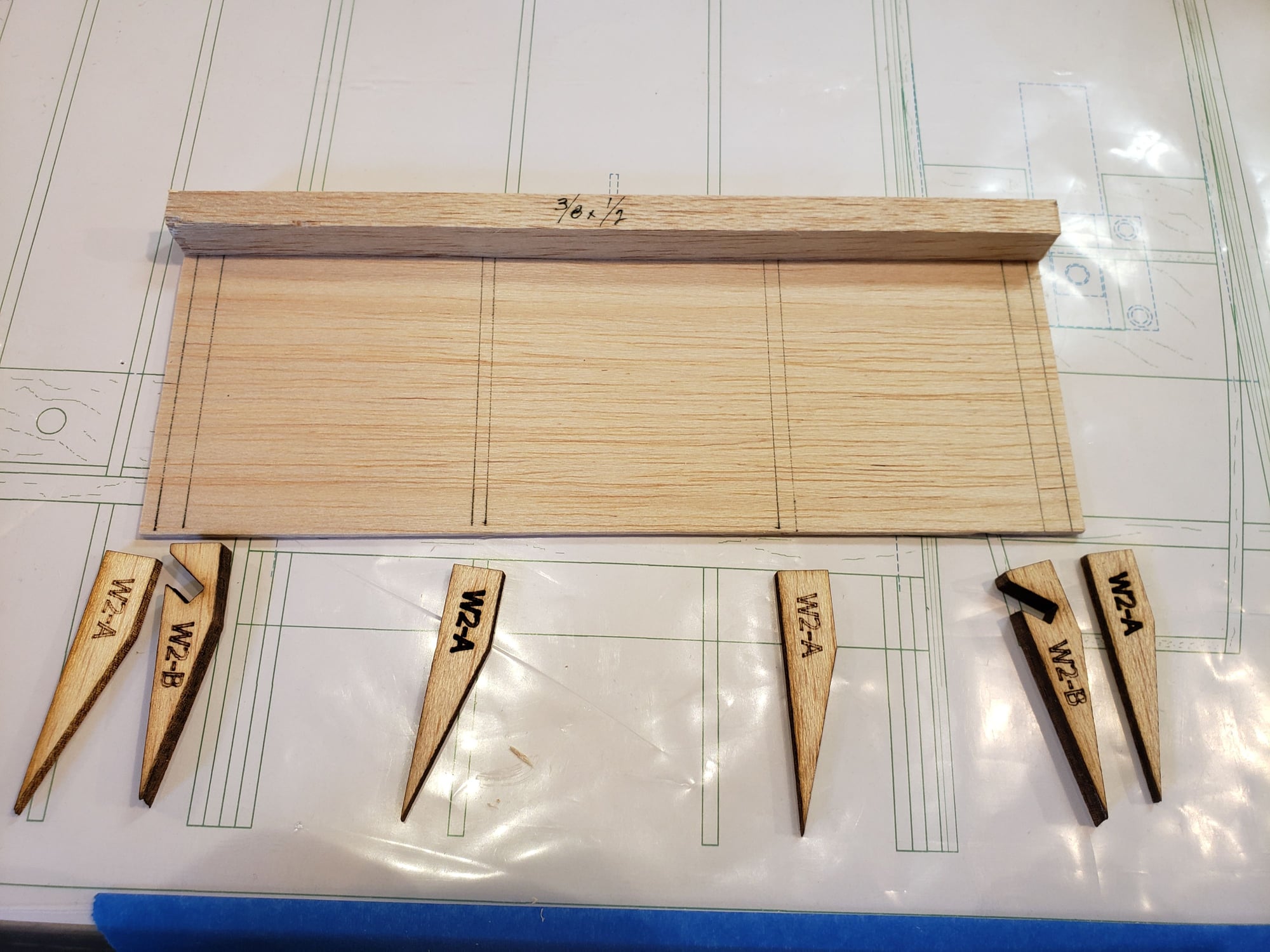
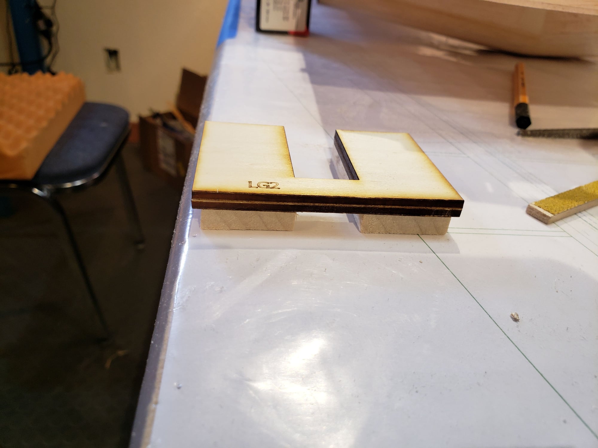
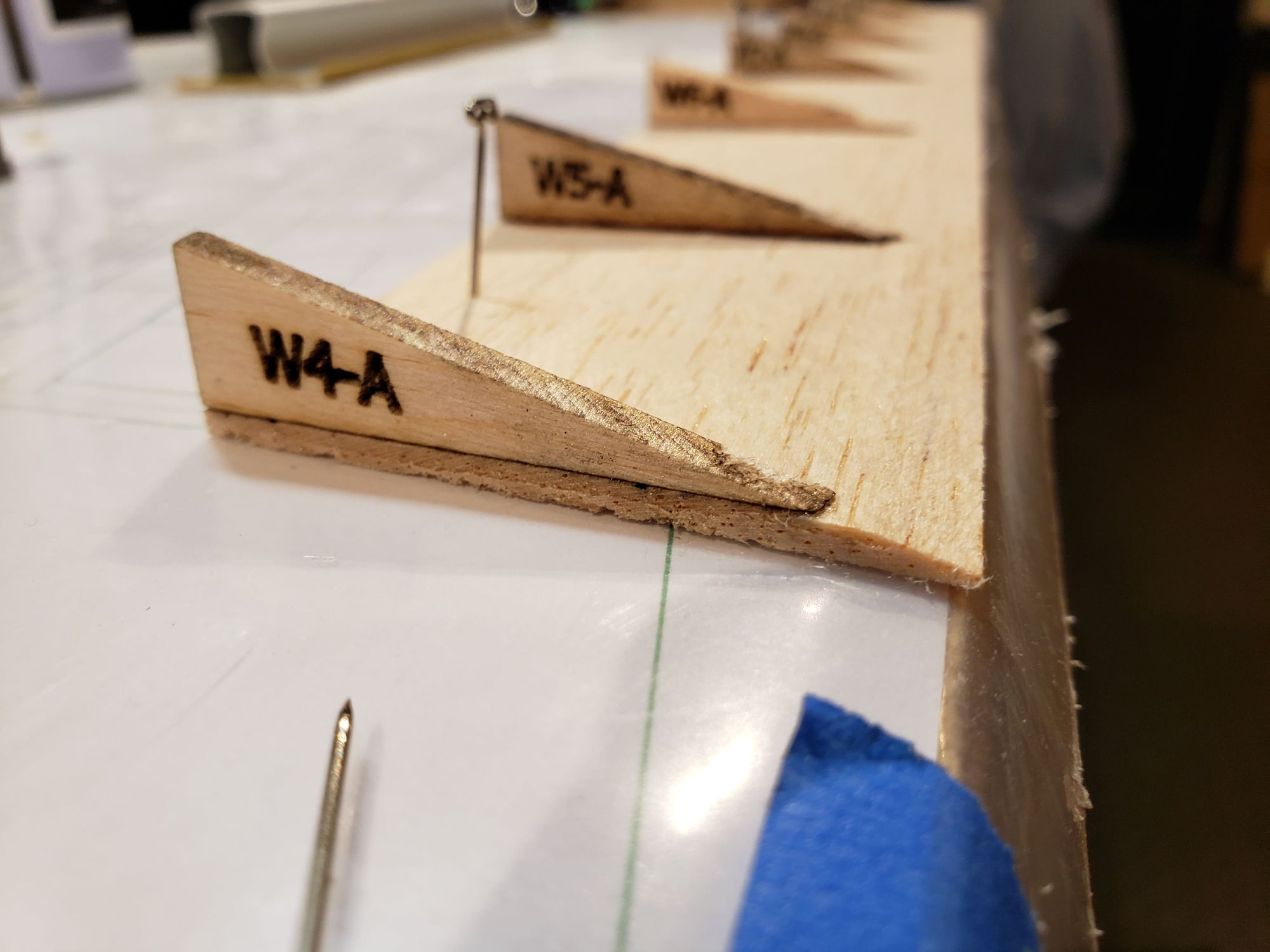
There are 8 hinges across the 4 flap segments. All the hinges need to be set the same or the flap segments will not move consistently or maybe even correctly. I designed 1/4" blocks to go in the wing and flap segment to set this angle.
 11-07-2023, 03:00 PM
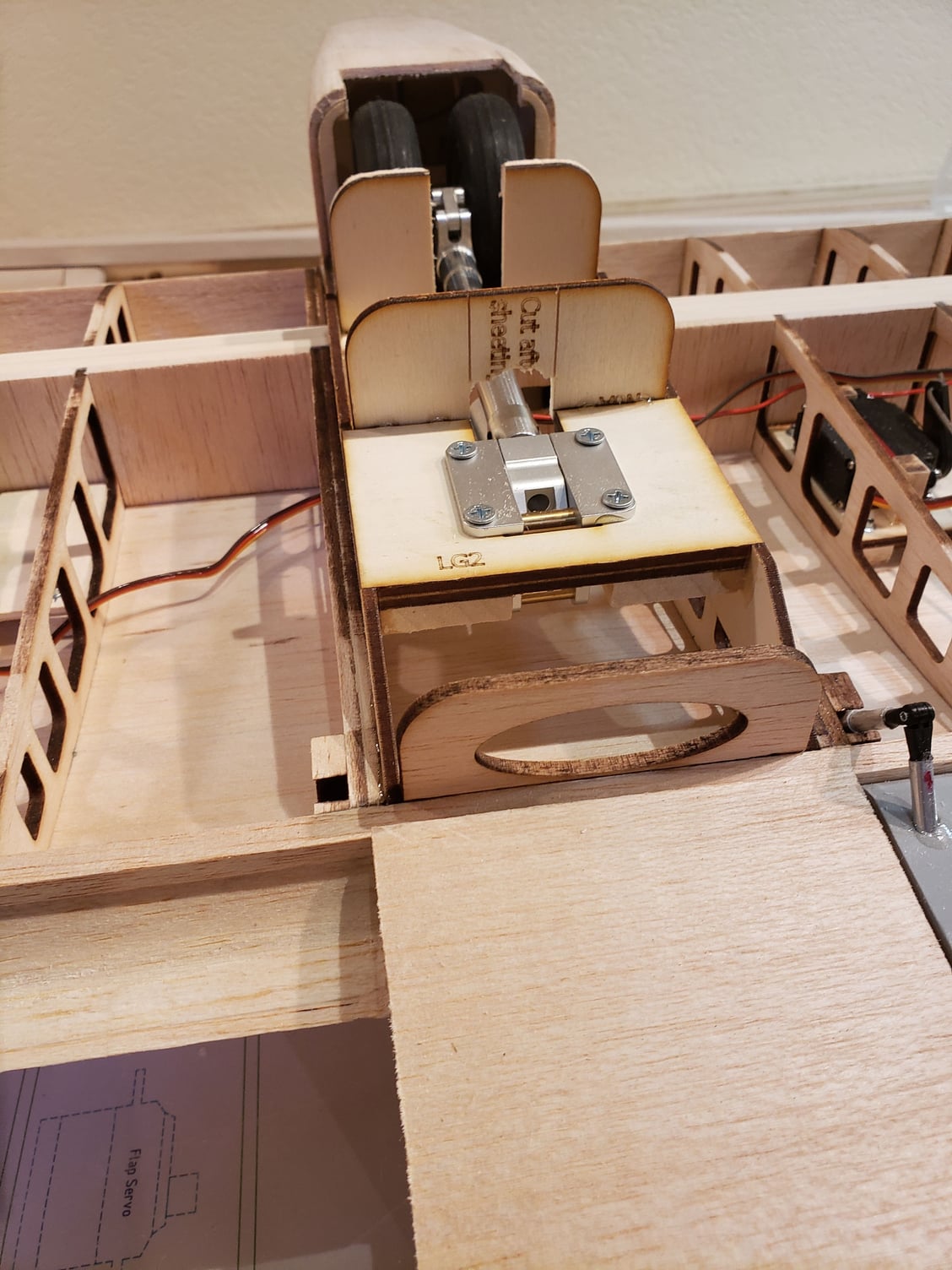
#58
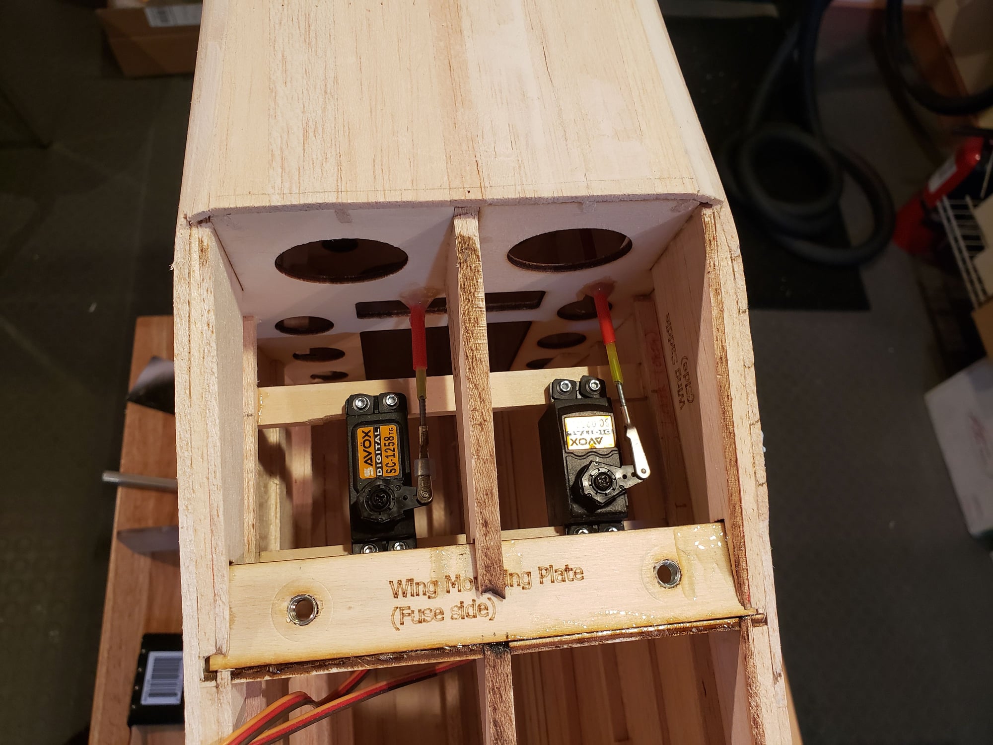
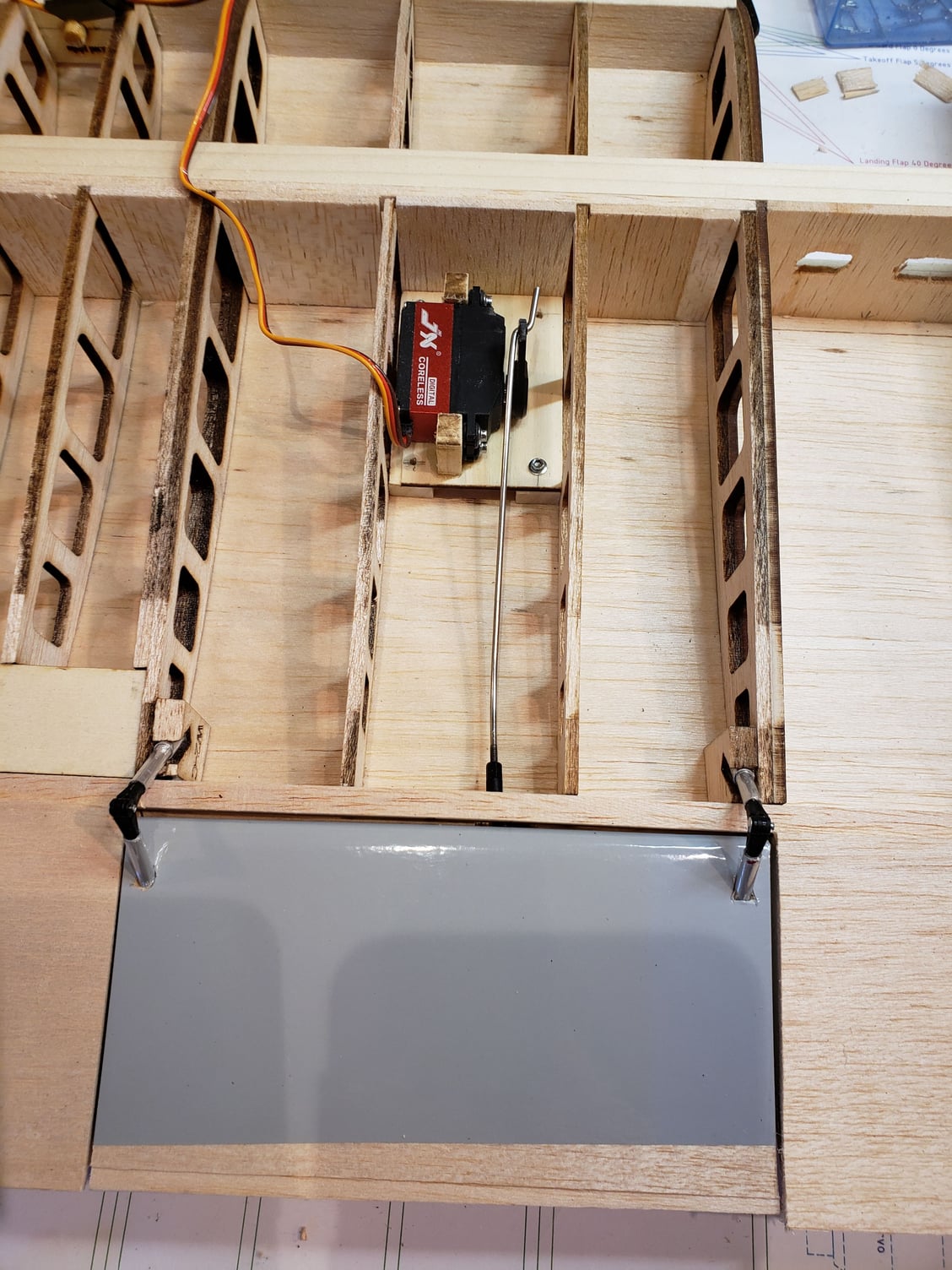
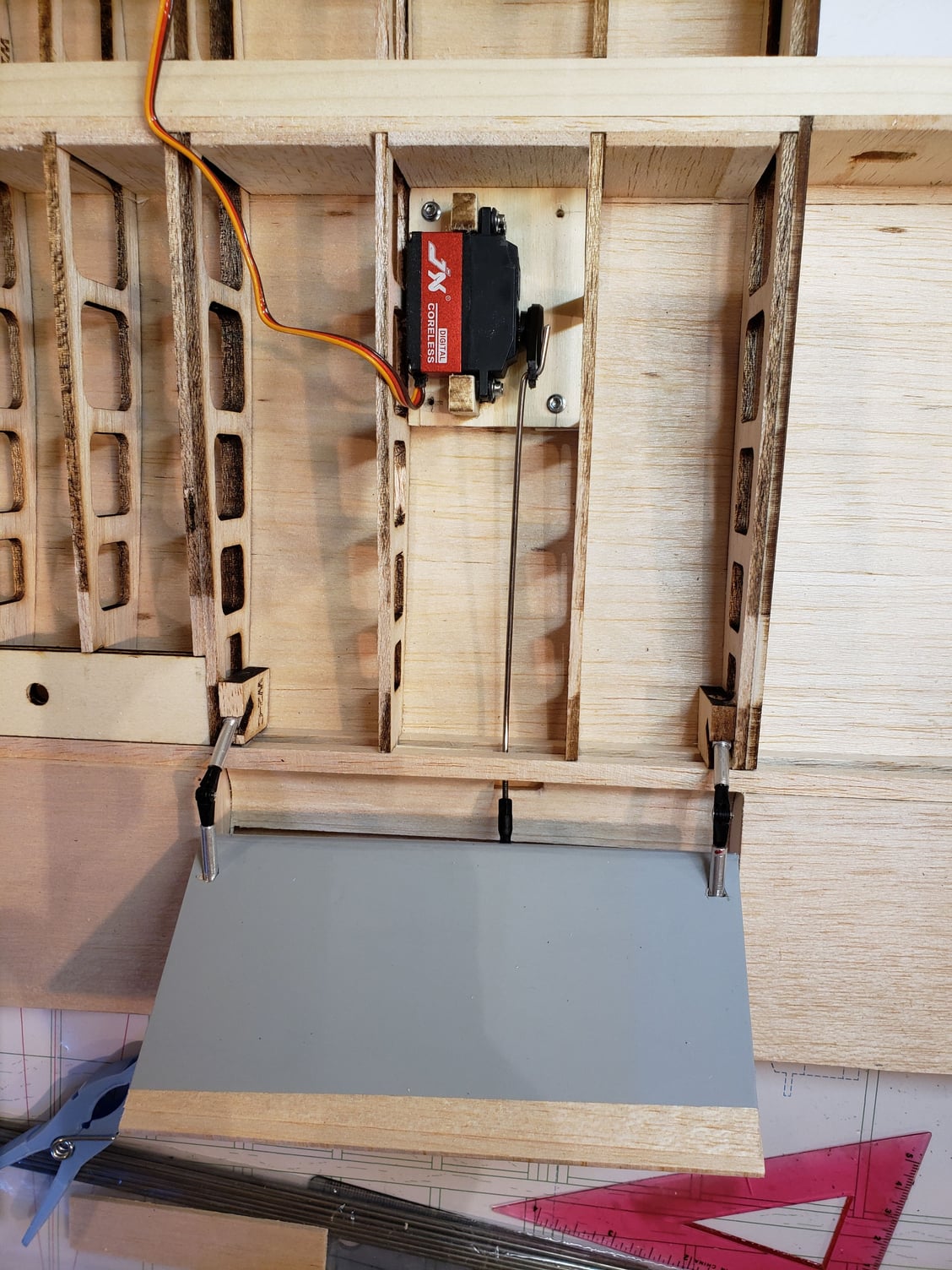
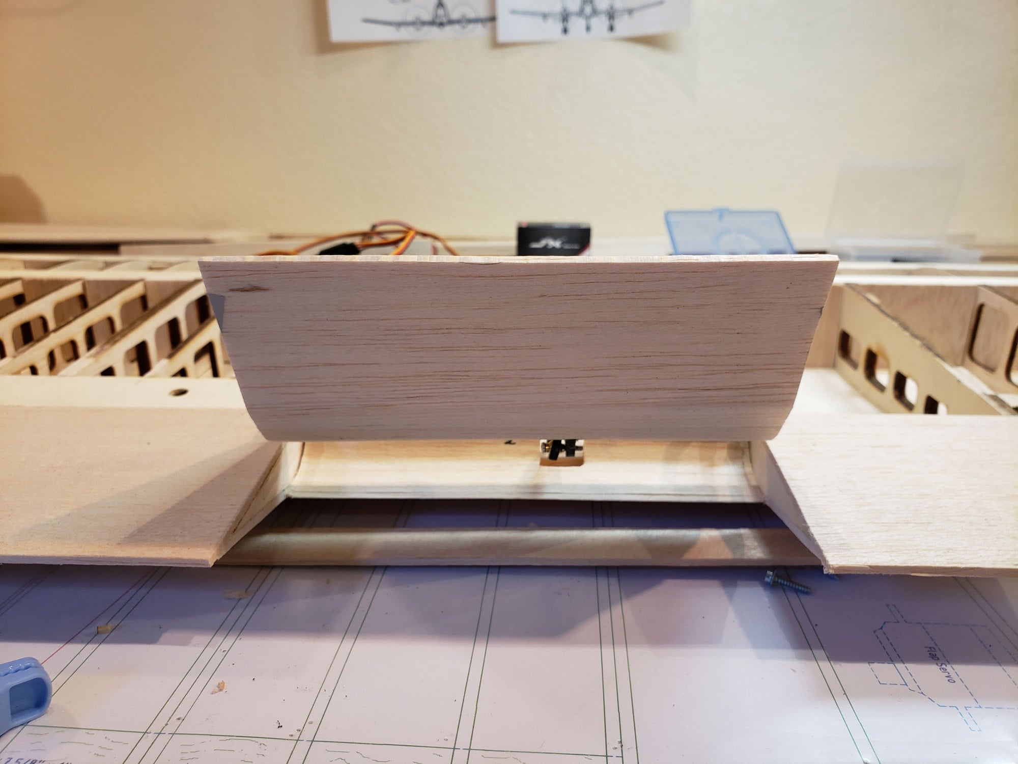
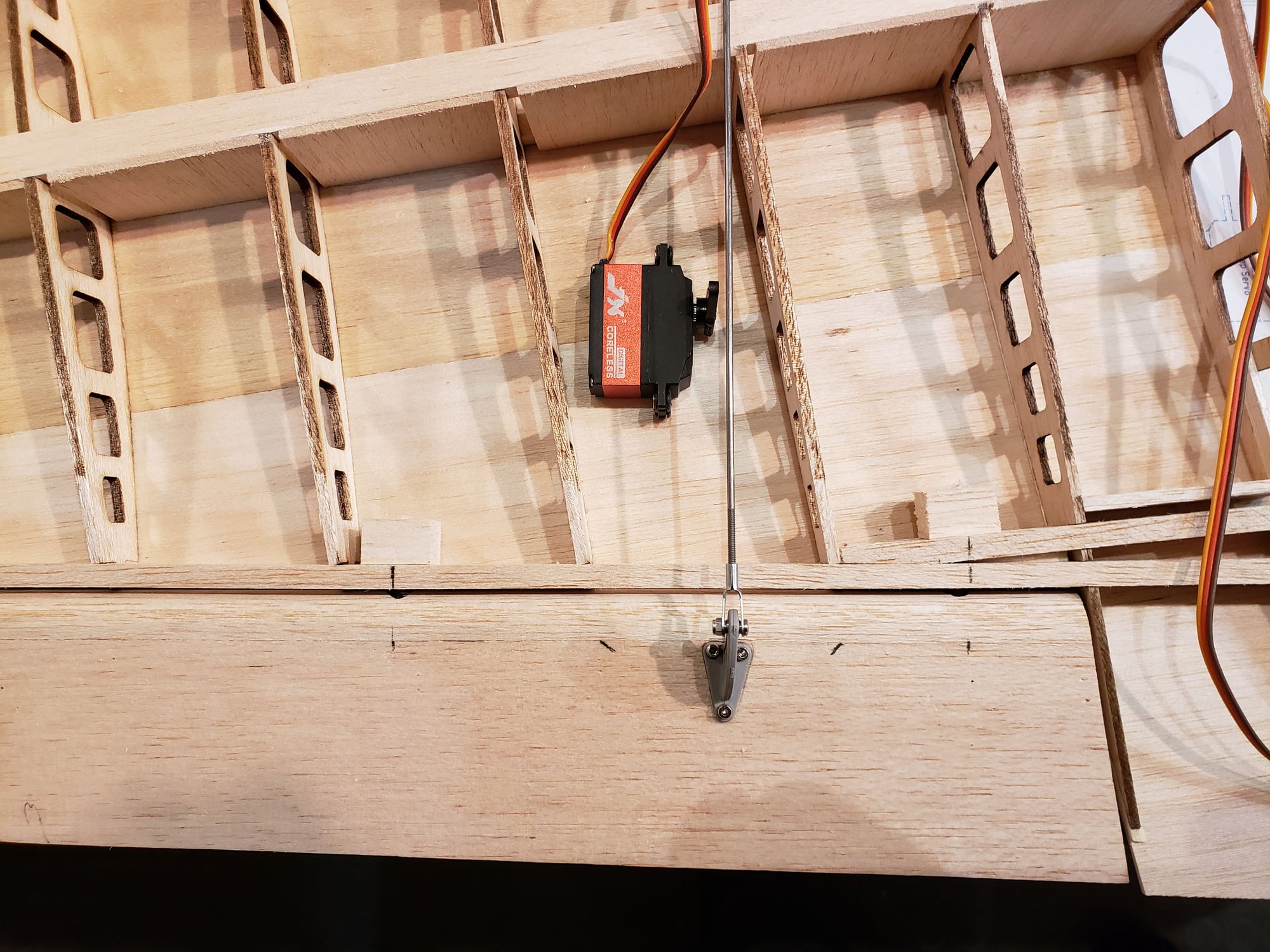
Here's the flap in place. It needs to be held at the correct angle to the wing. The blocks I made only get you close, this will make the alignment near perfect. The last 3 picts show the flap and servo mechanism installed and functional.
11-16-2023, 05:29 PM
#59
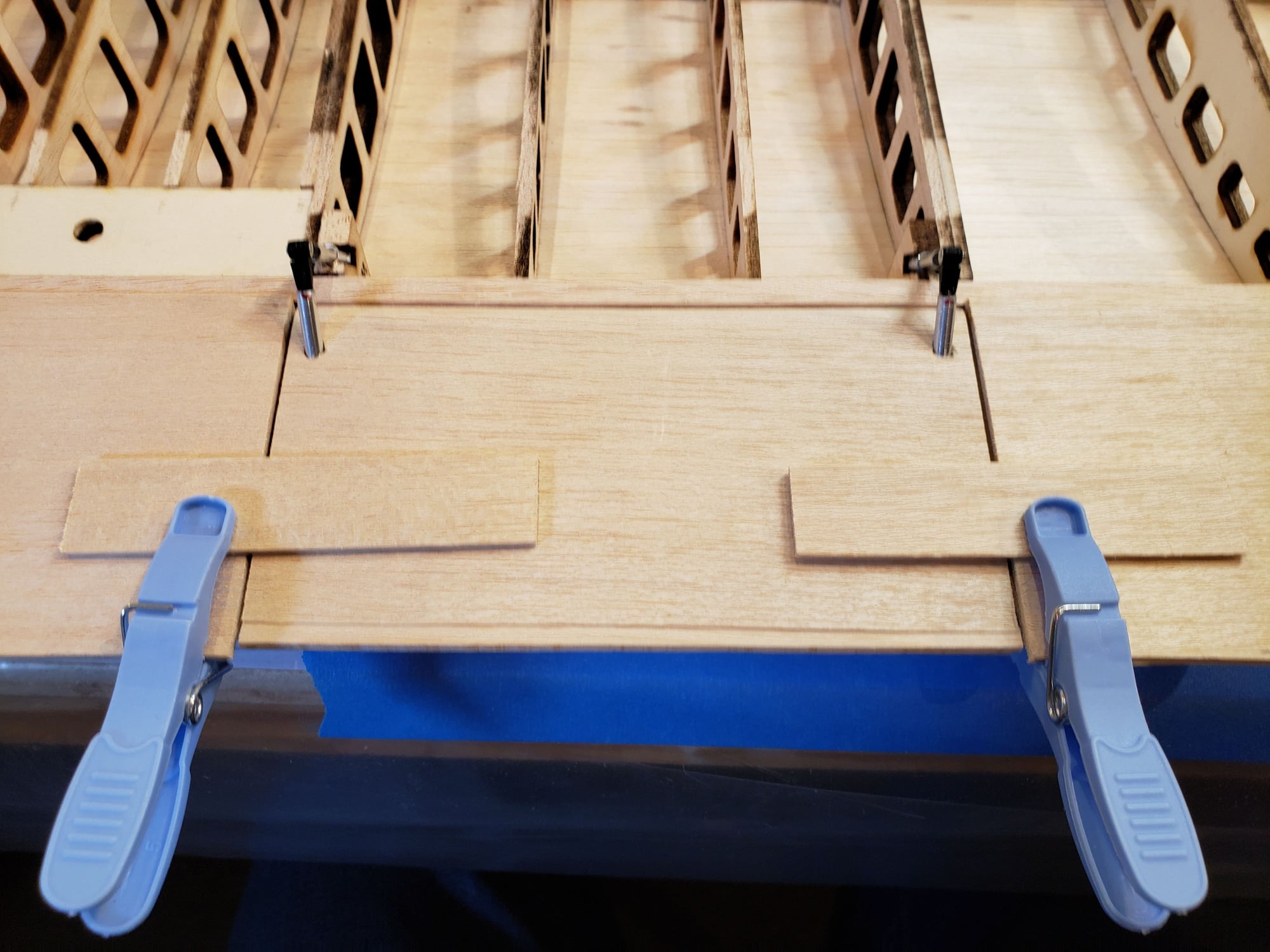
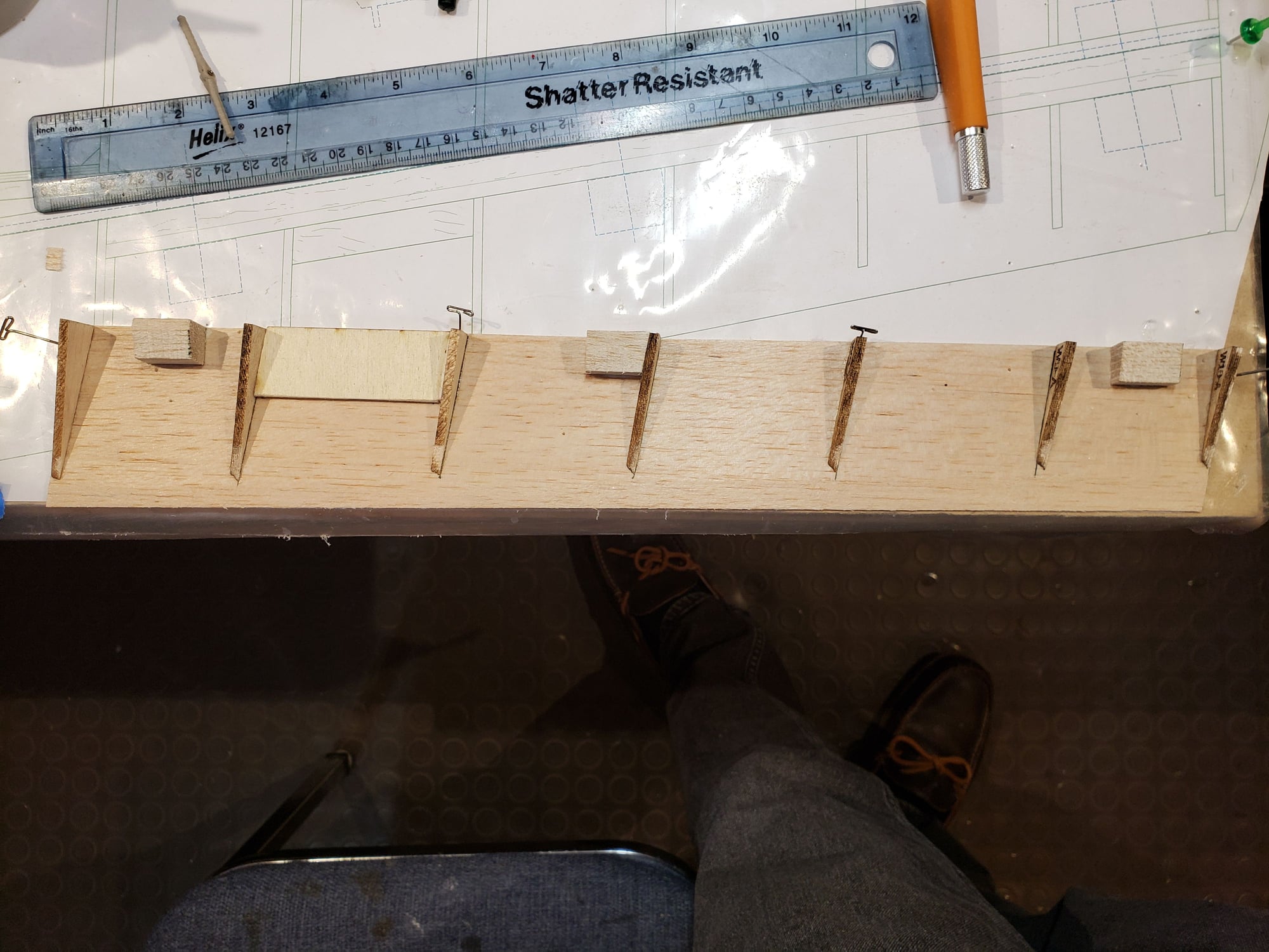
To enable a smooth flow of air through the slot when the flap is open, I use 1/32" balsa to line the gap on the TE of the wing.
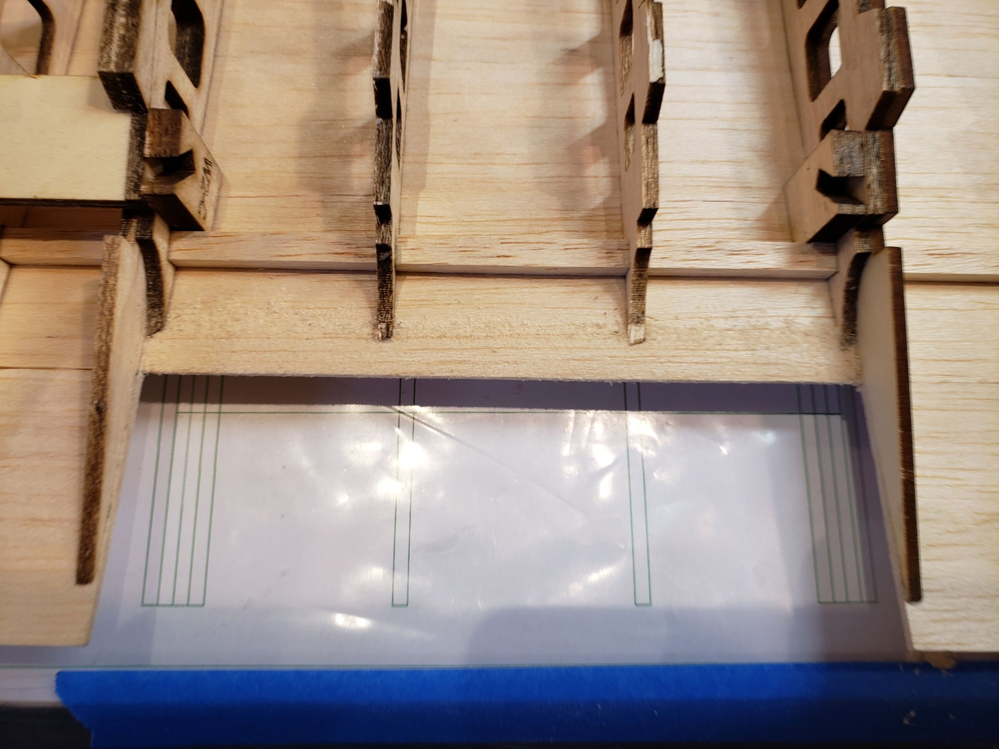
TE with cutouts to support sheeting.
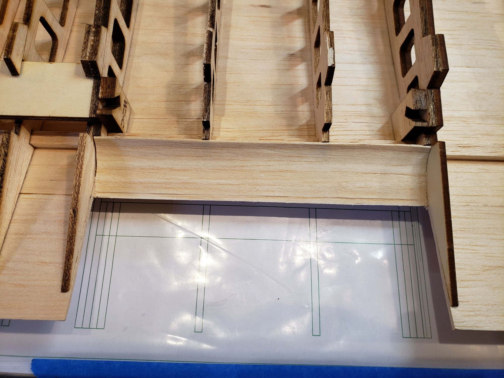
1/32" sheet added
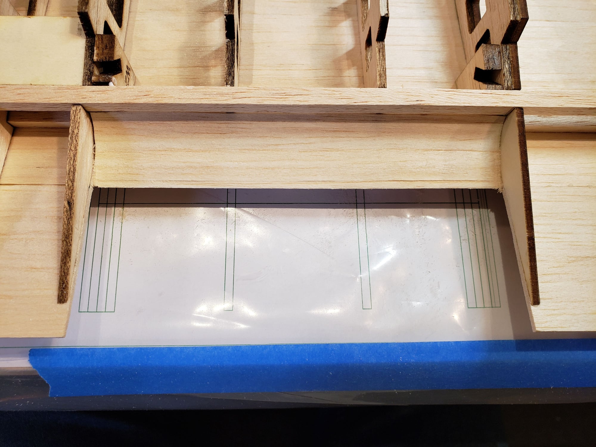
Rear spar added.
TE with cutouts to support sheeting.
1/32" sheet added
Rear spar added.
11-16-2023, 05:38 PM
#60
Getting back to work on the nacelles ... The cowl is a close fit around the motor, which does not leave a lot of room for heat to dissipate. So, I will route air from the lower intake up to the motor and out the TE of the nacelle. Here's how it comes together ...
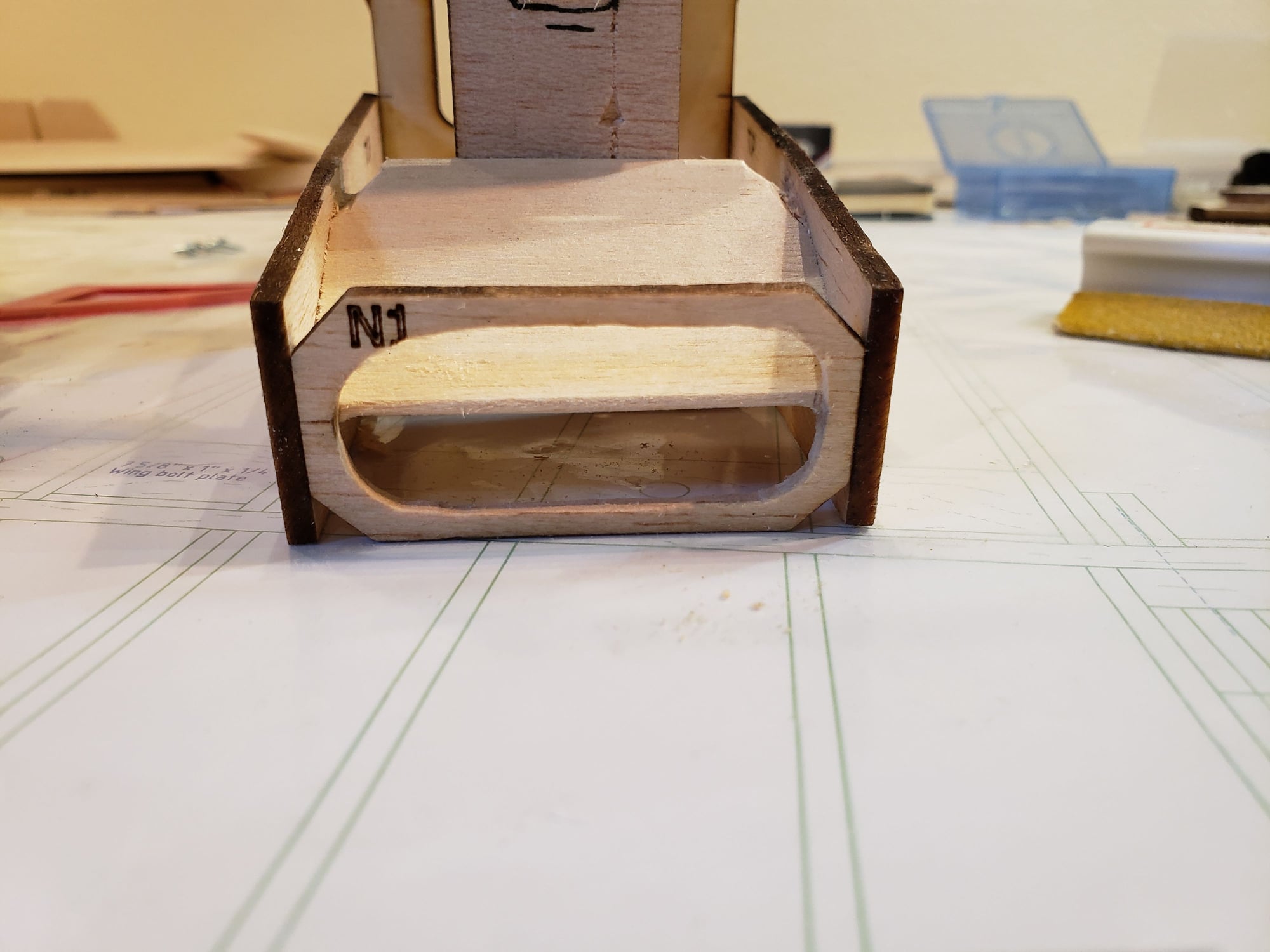
Add a divider to split the airflow coming in. The upper flow will go to the motor, the lower flow will go to the ESC.
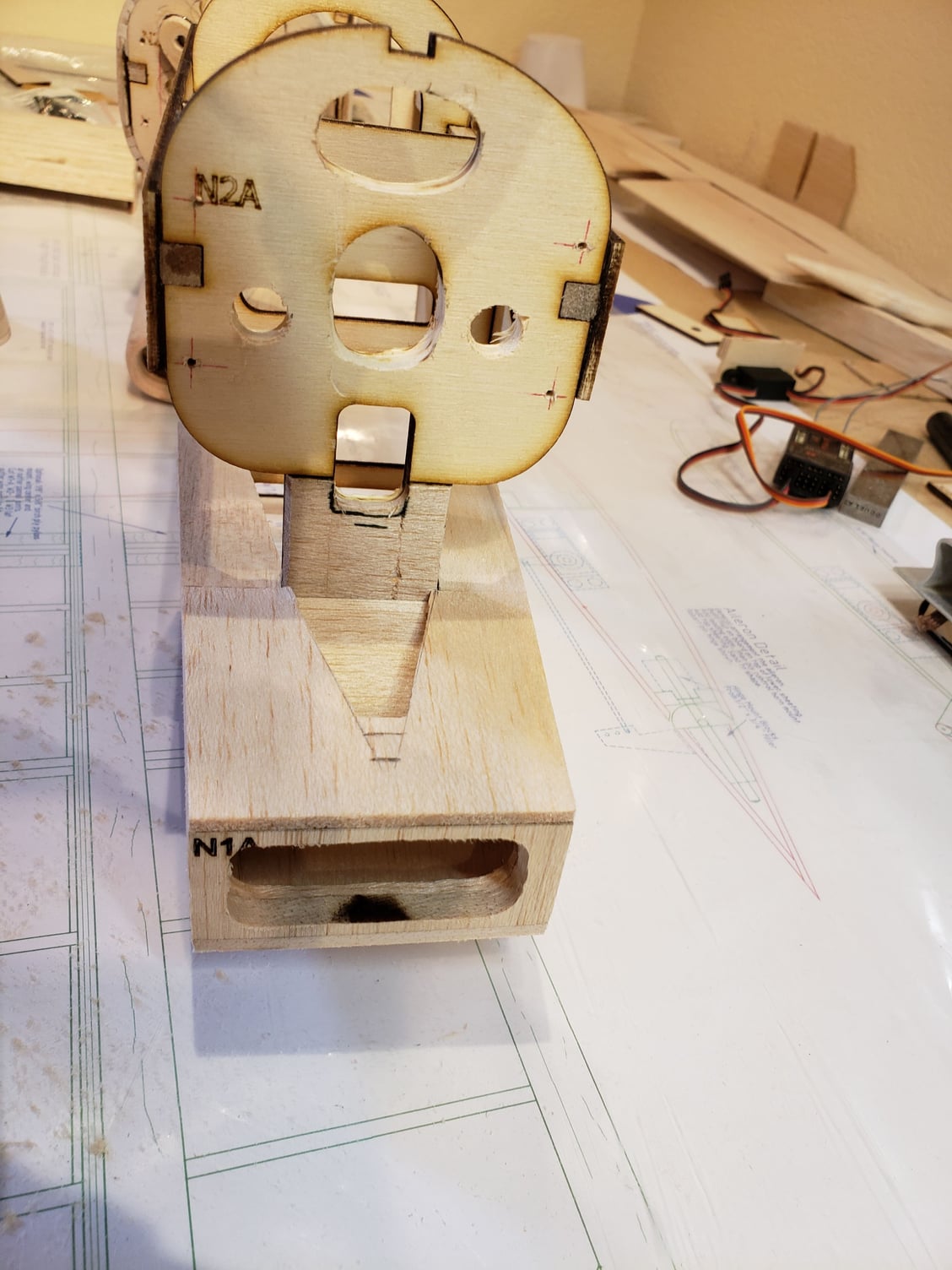
Build out the rest of the intake, cutting a hole the shape of the 'V' fairing that separates the cowl from the scoop.
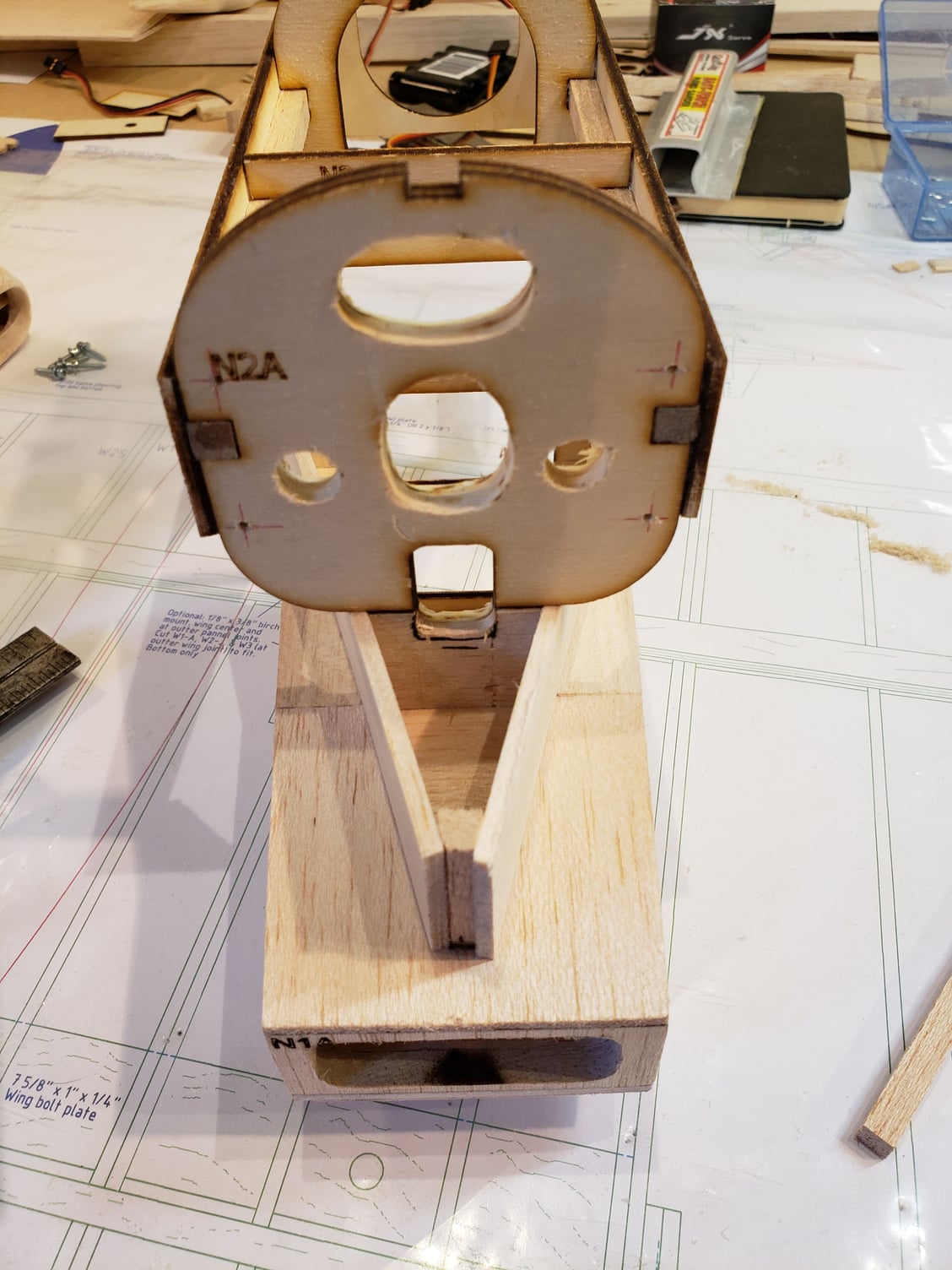
Add the 'V' shaped fairing. Cut holes in the fairing to allow the air to escape.
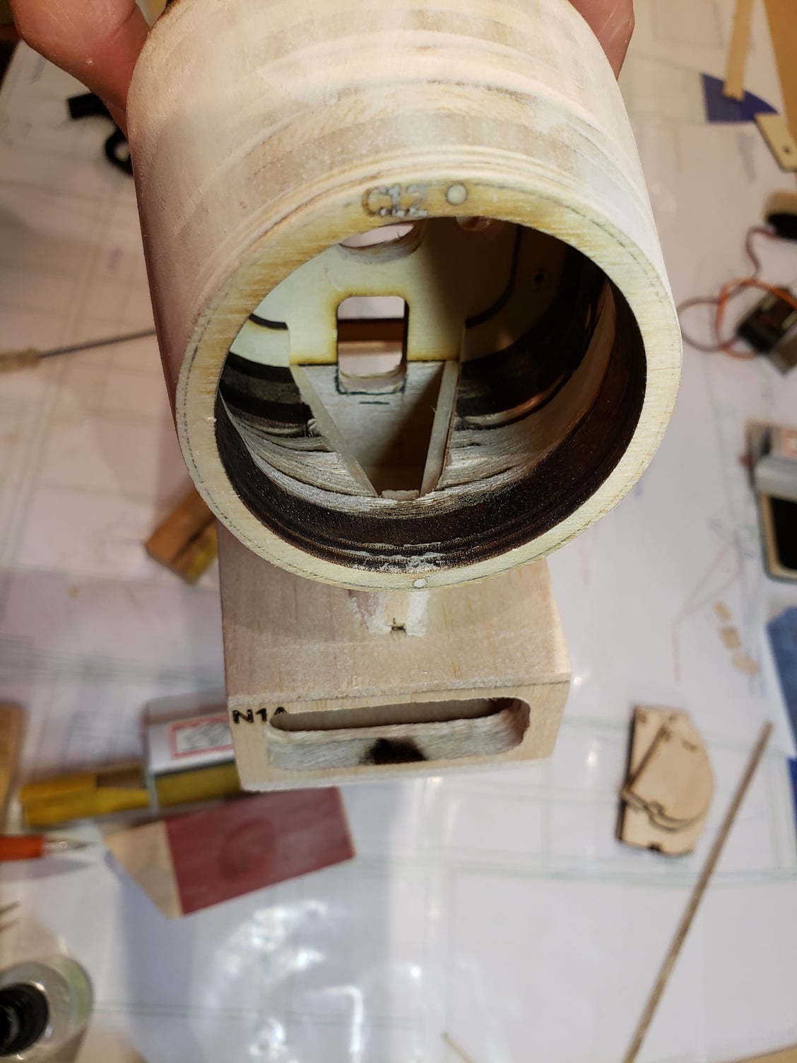
Cut an opening in the bottom of the cowl to fit over the fairing's opening.
Add a divider to split the airflow coming in. The upper flow will go to the motor, the lower flow will go to the ESC.
Build out the rest of the intake, cutting a hole the shape of the 'V' fairing that separates the cowl from the scoop.
Add the 'V' shaped fairing. Cut holes in the fairing to allow the air to escape.
Cut an opening in the bottom of the cowl to fit over the fairing's opening.
 11-29-2023, 04:43 PM
#64
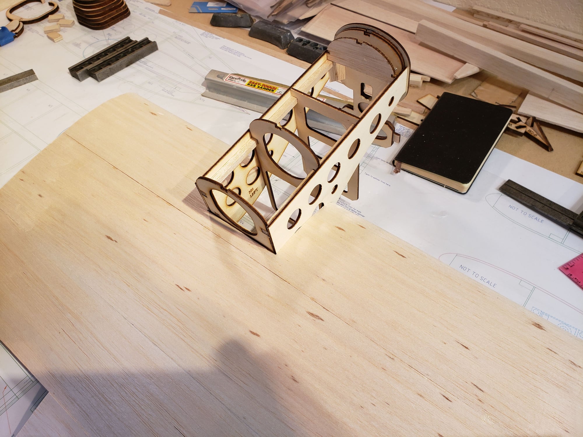
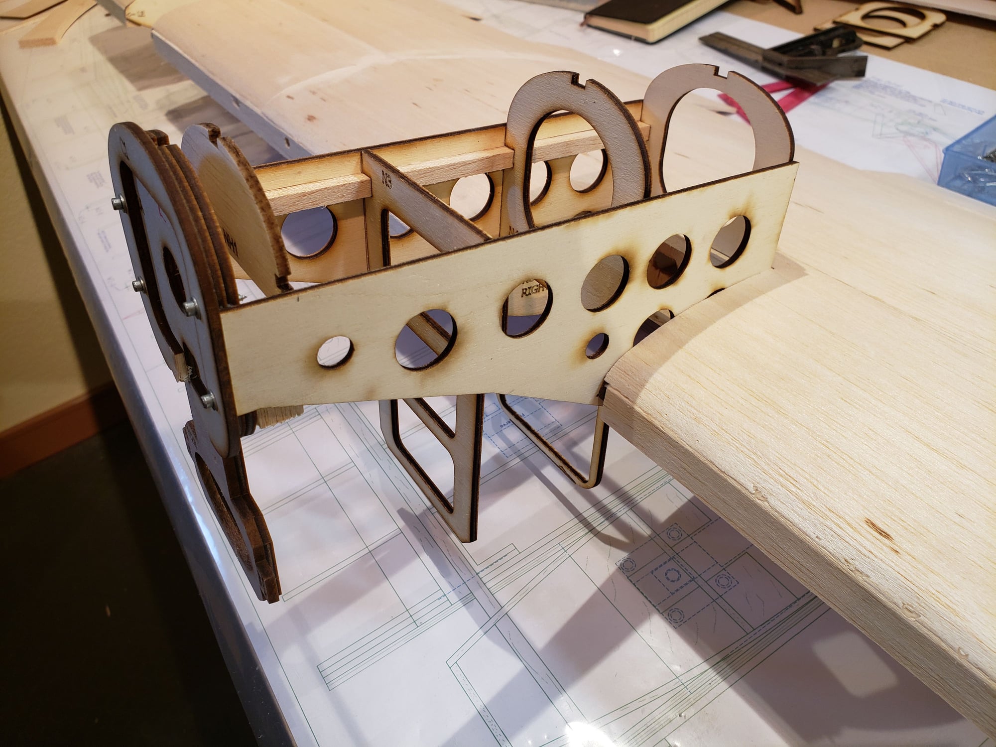
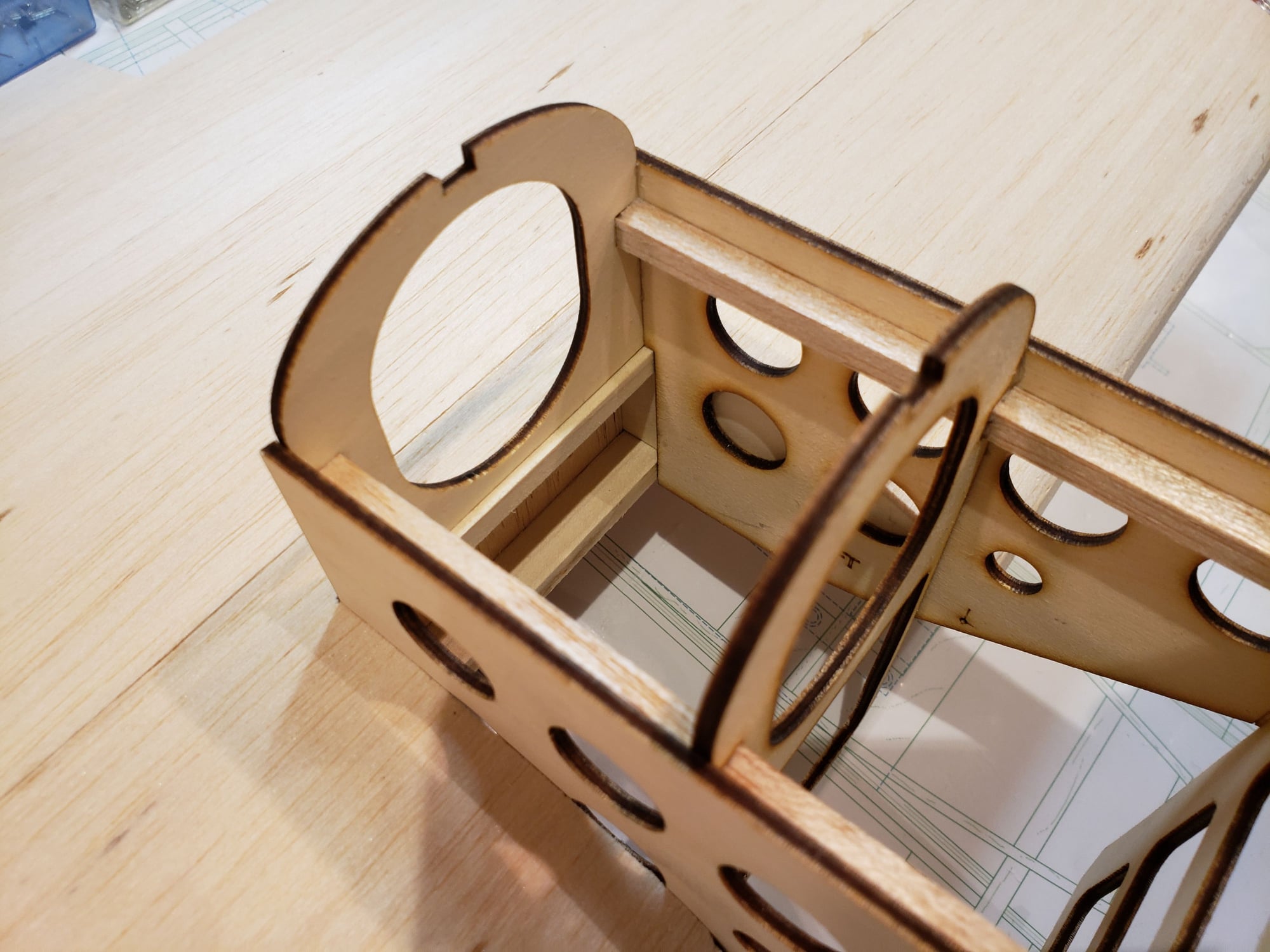
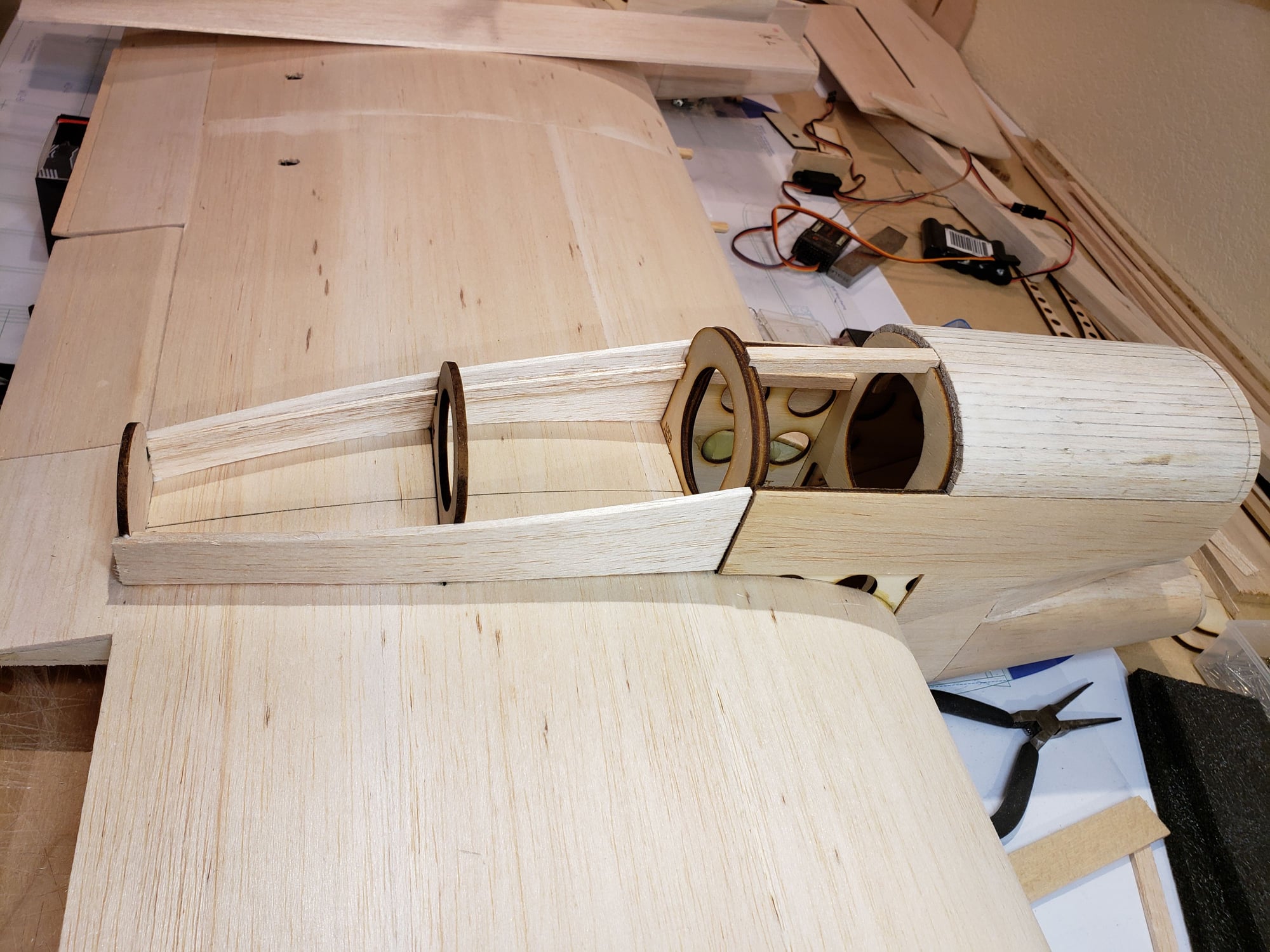
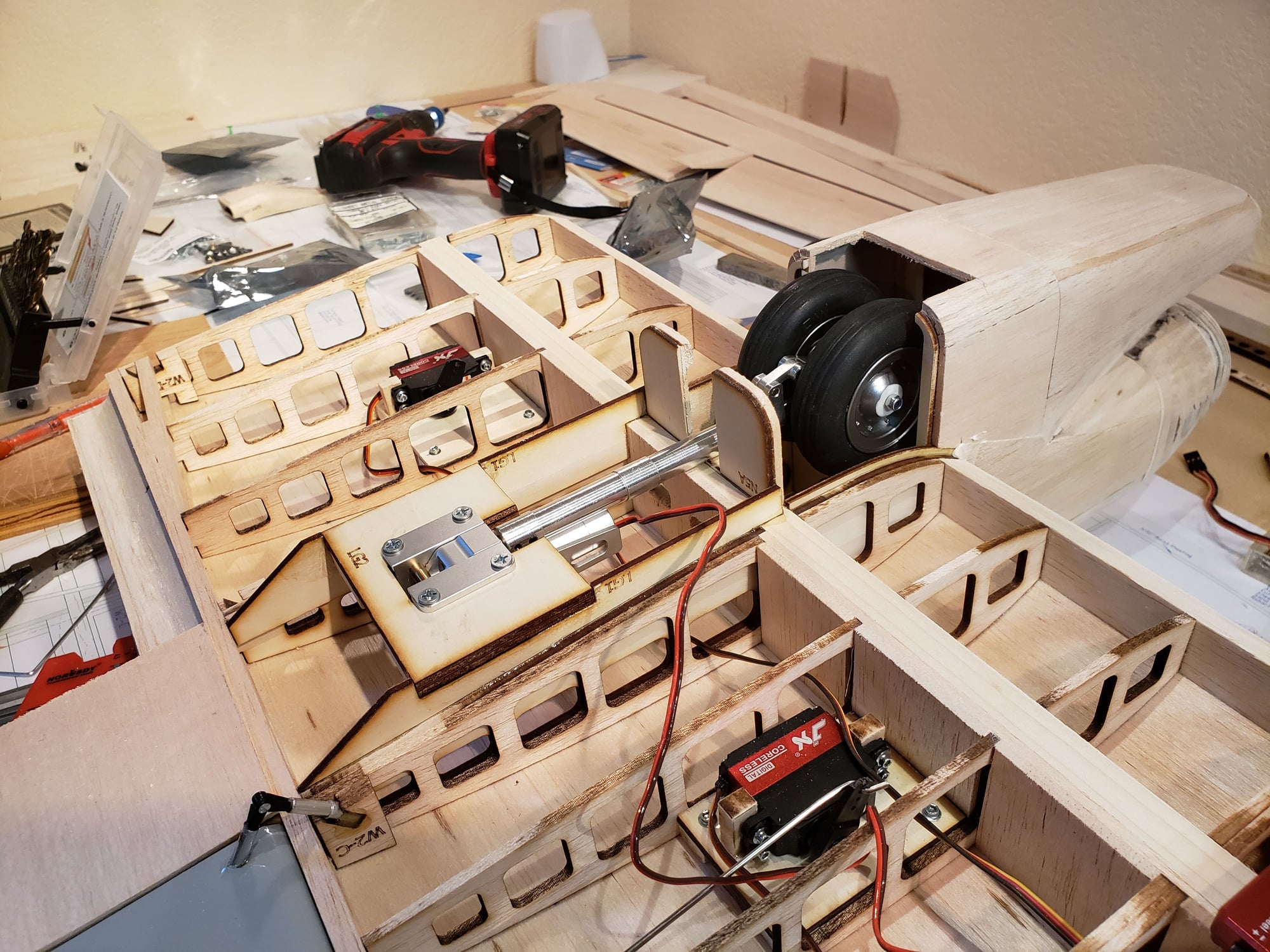
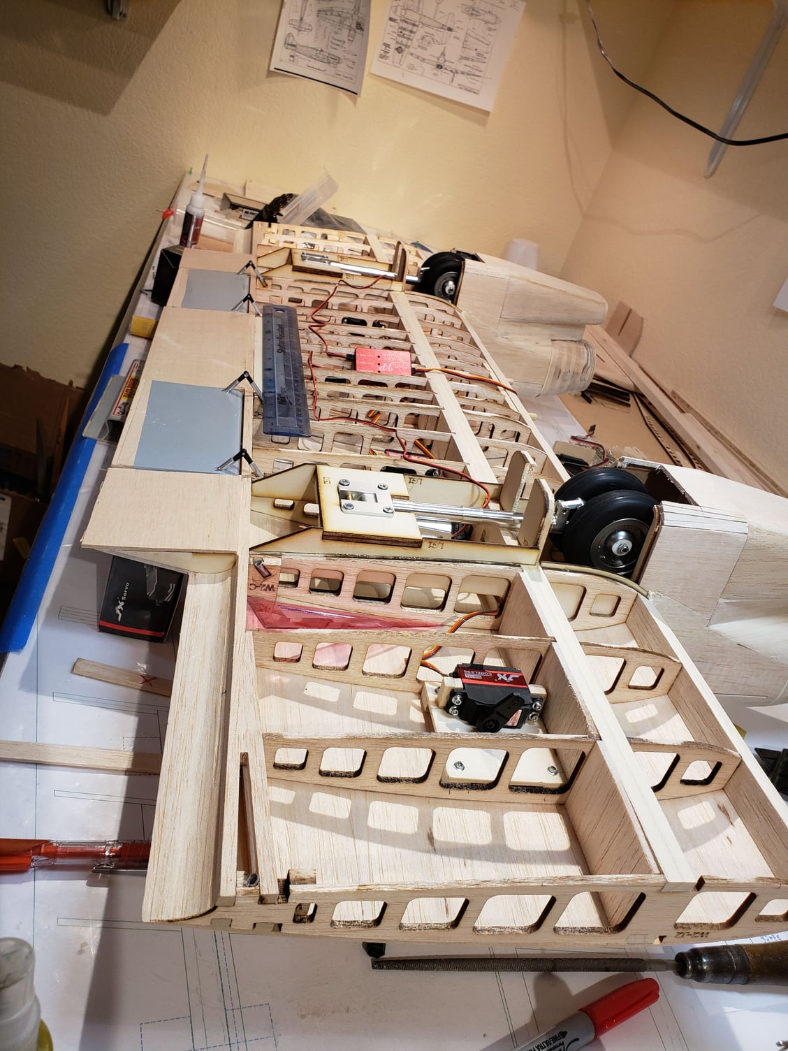
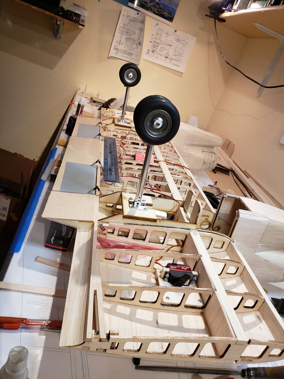
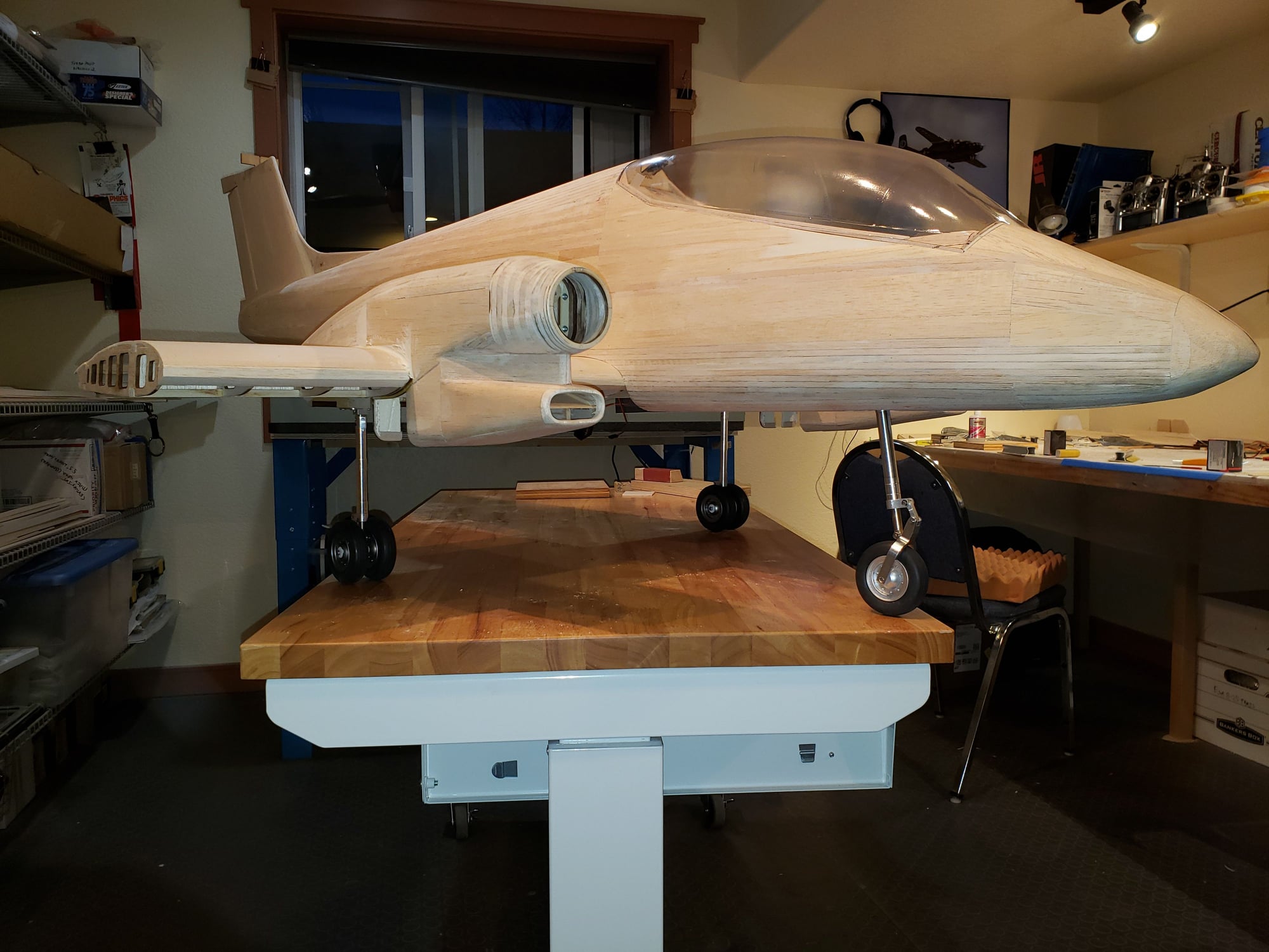
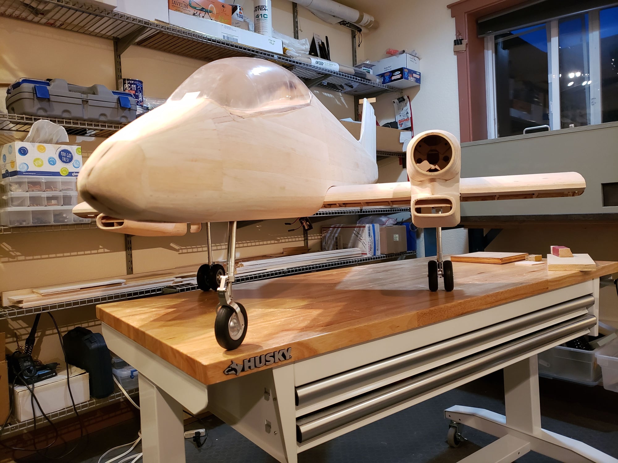
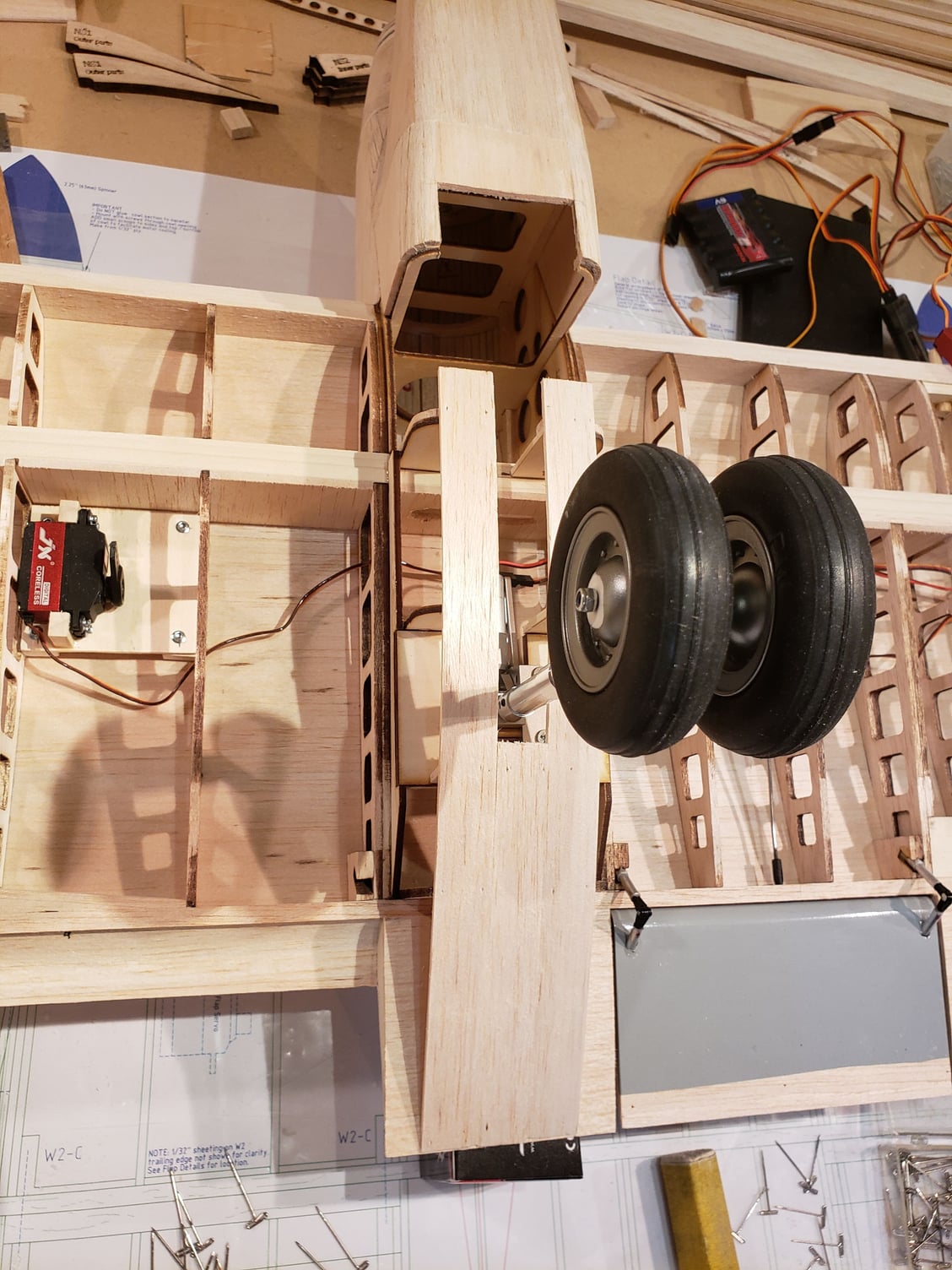
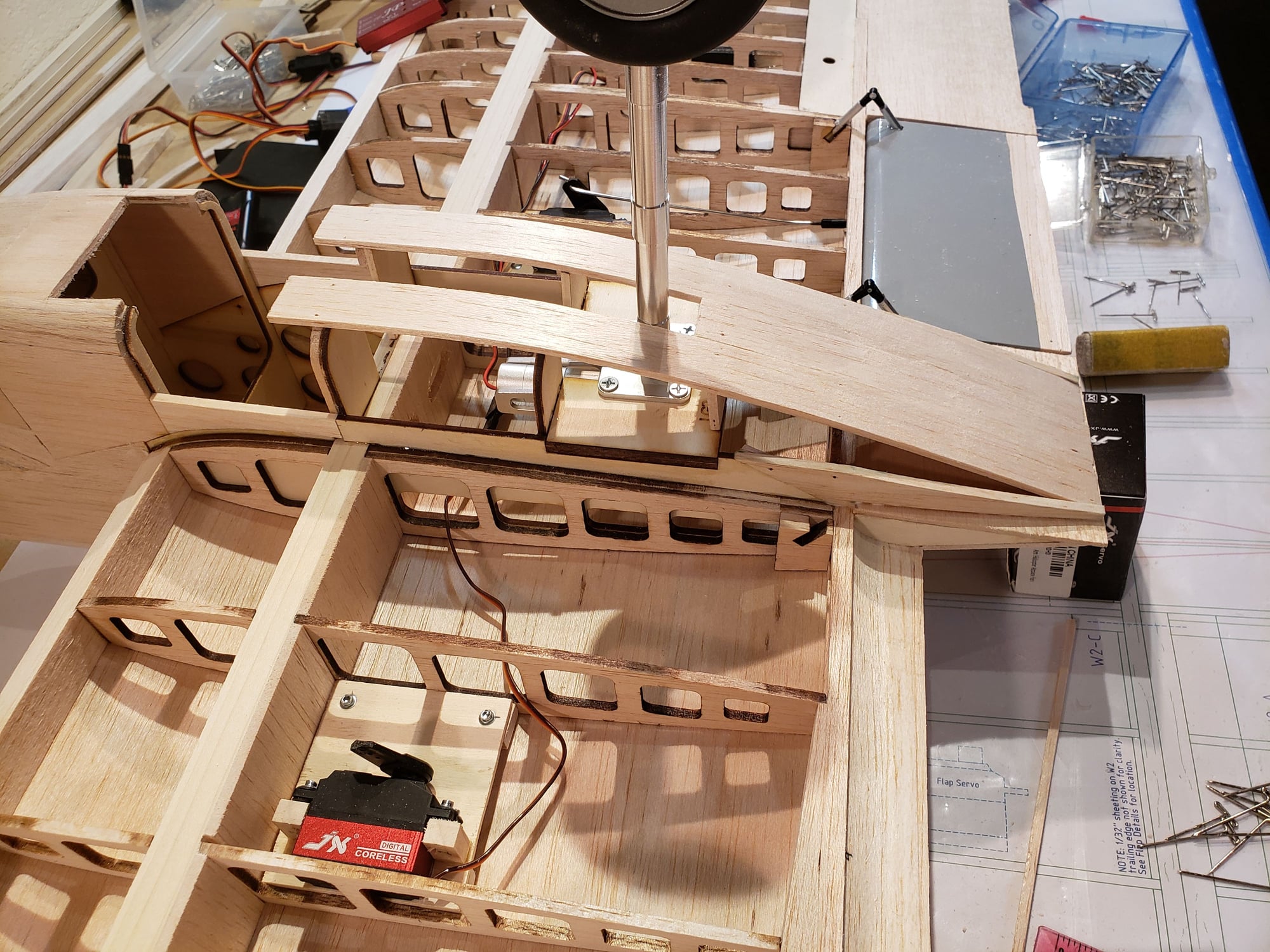
Installing the main gear ... first an observation. It's interesting to me that the Pucara has dual wheels on each main gear strut. Typically, this might be done for load bearing reasons, but this isn't that heavy a plane. I'm guessing that using dual wheels enabled them to have the struct retract under the main spar and at the same time minimize the size of the nacelle. But if anyone knows for sure ... please post!
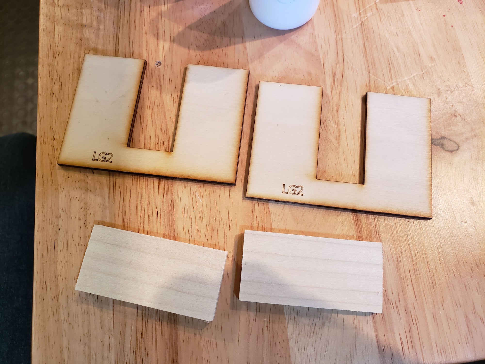
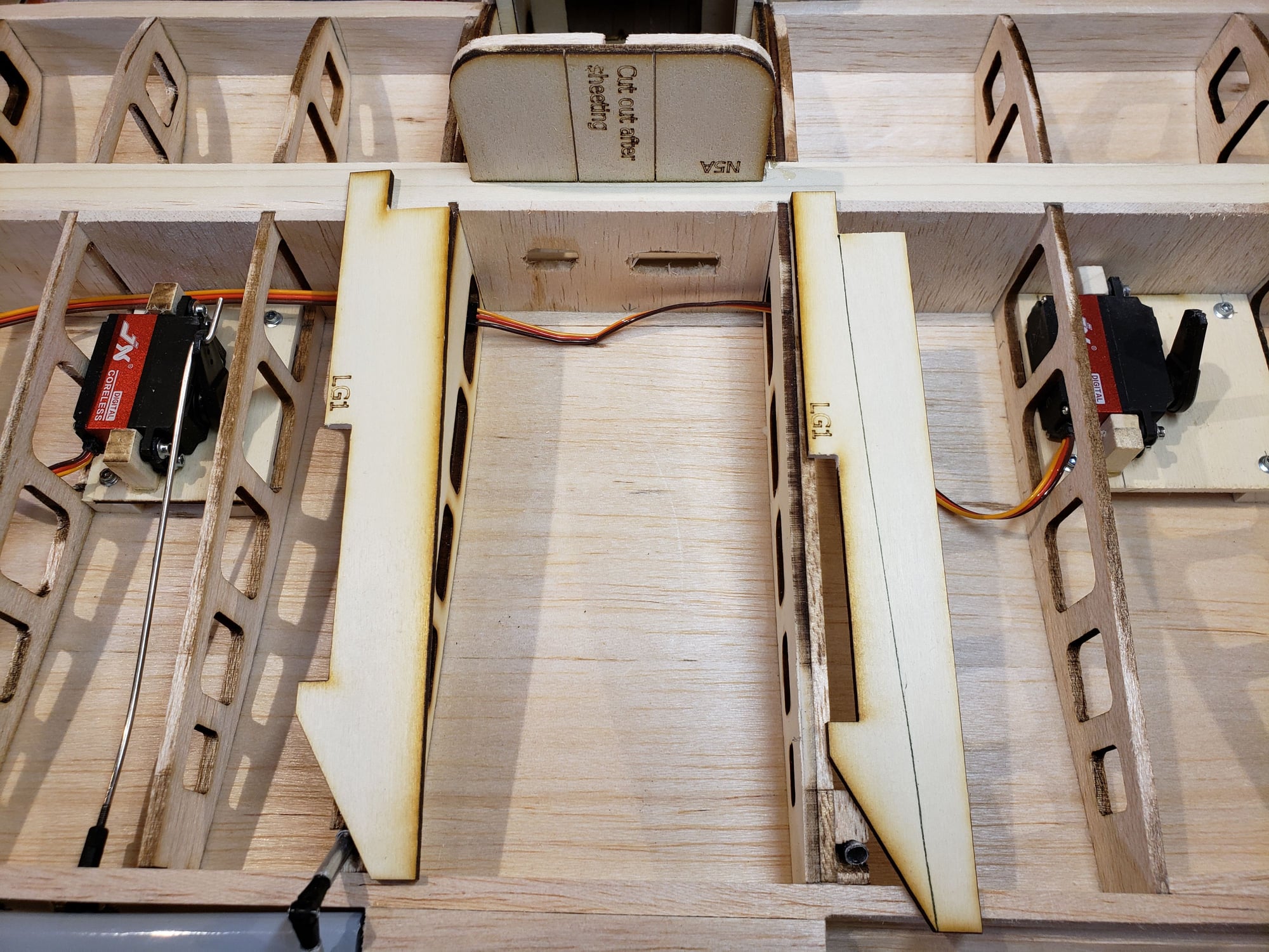
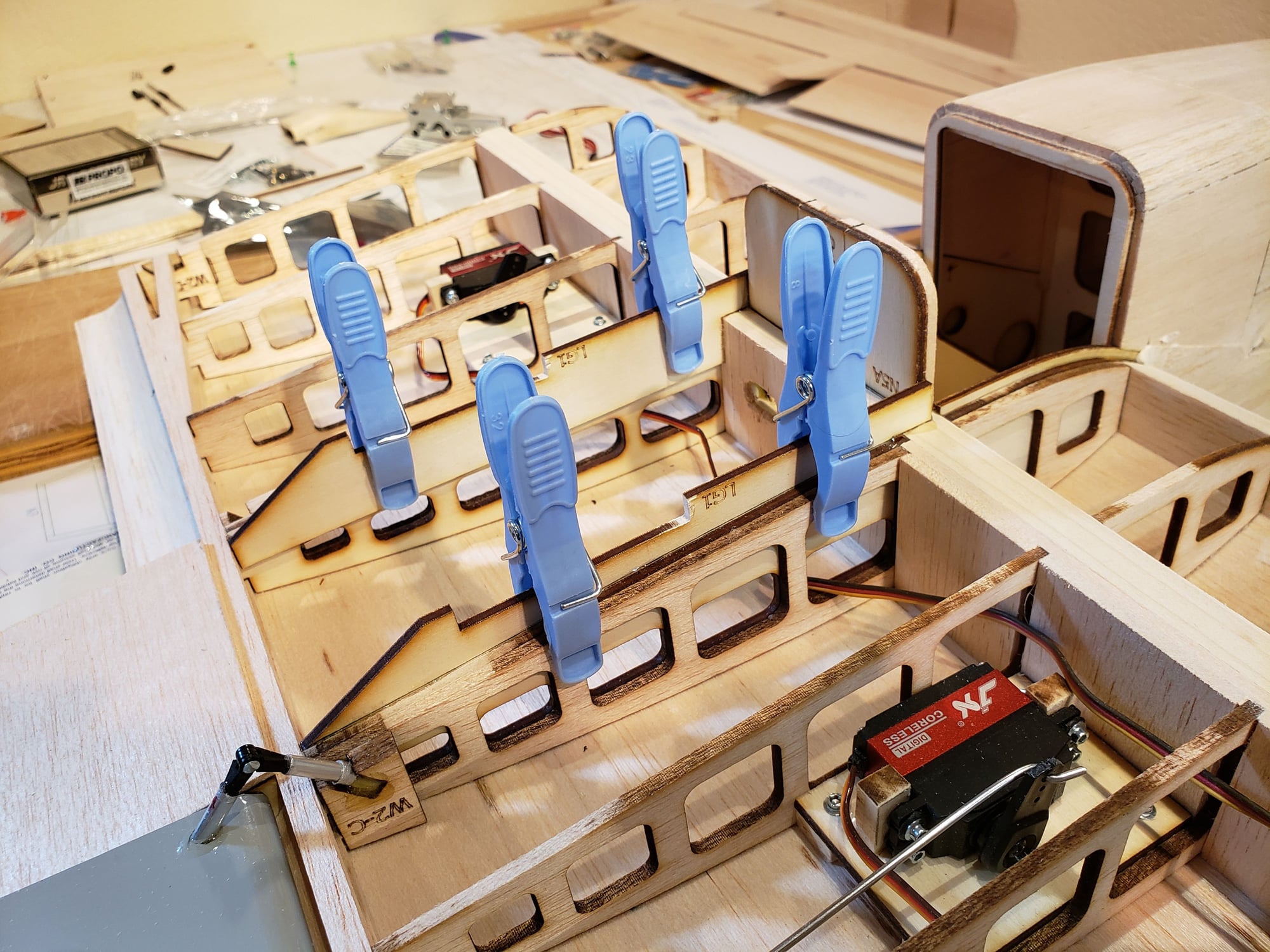
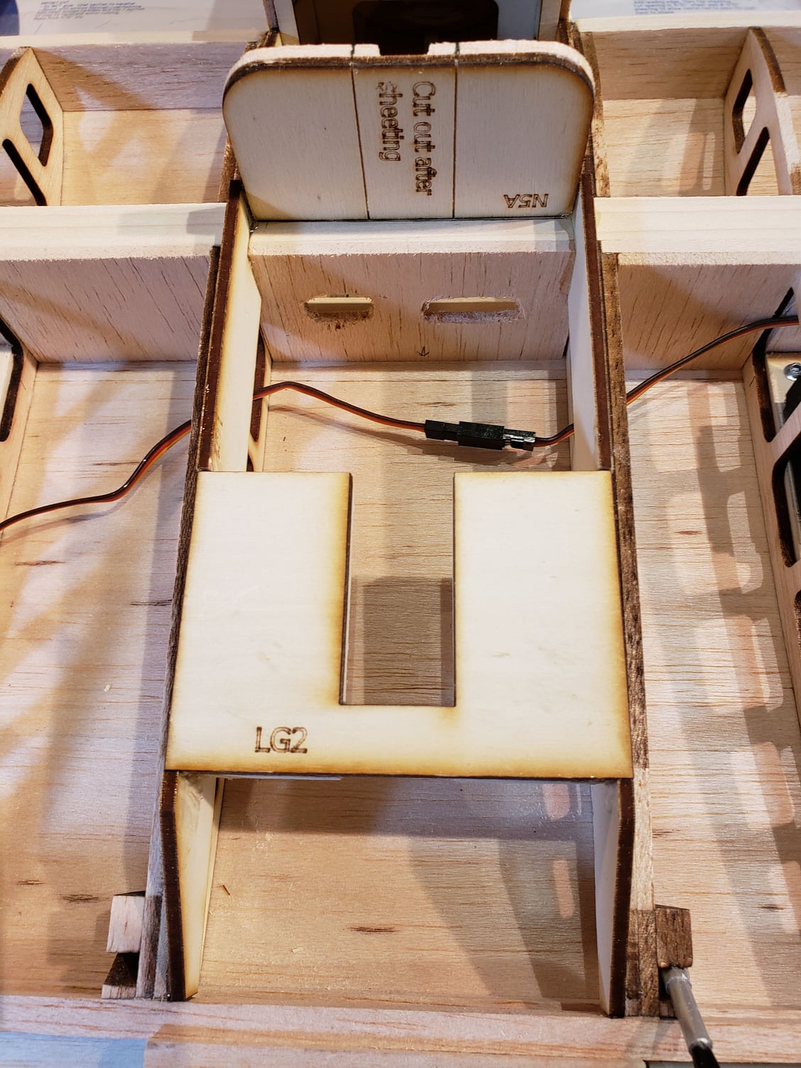
I'll go with a scale dual wheel setup on mine. The gear is mounted to 1/4" ply and 1/4" hardwood rails (they are under the ply). The ply mount plates are fitted into a notch in the ply ribs, which themselves tie into the main and secondary spars. Once these were fitted, the nacelle formers are put in place and then sheeted/planked.
There's a bunch of picts for this, so will break it into 2 posts. These are showing the buildout of the LG mount assembly.

 11-29-2023, 04:53 PM
#66
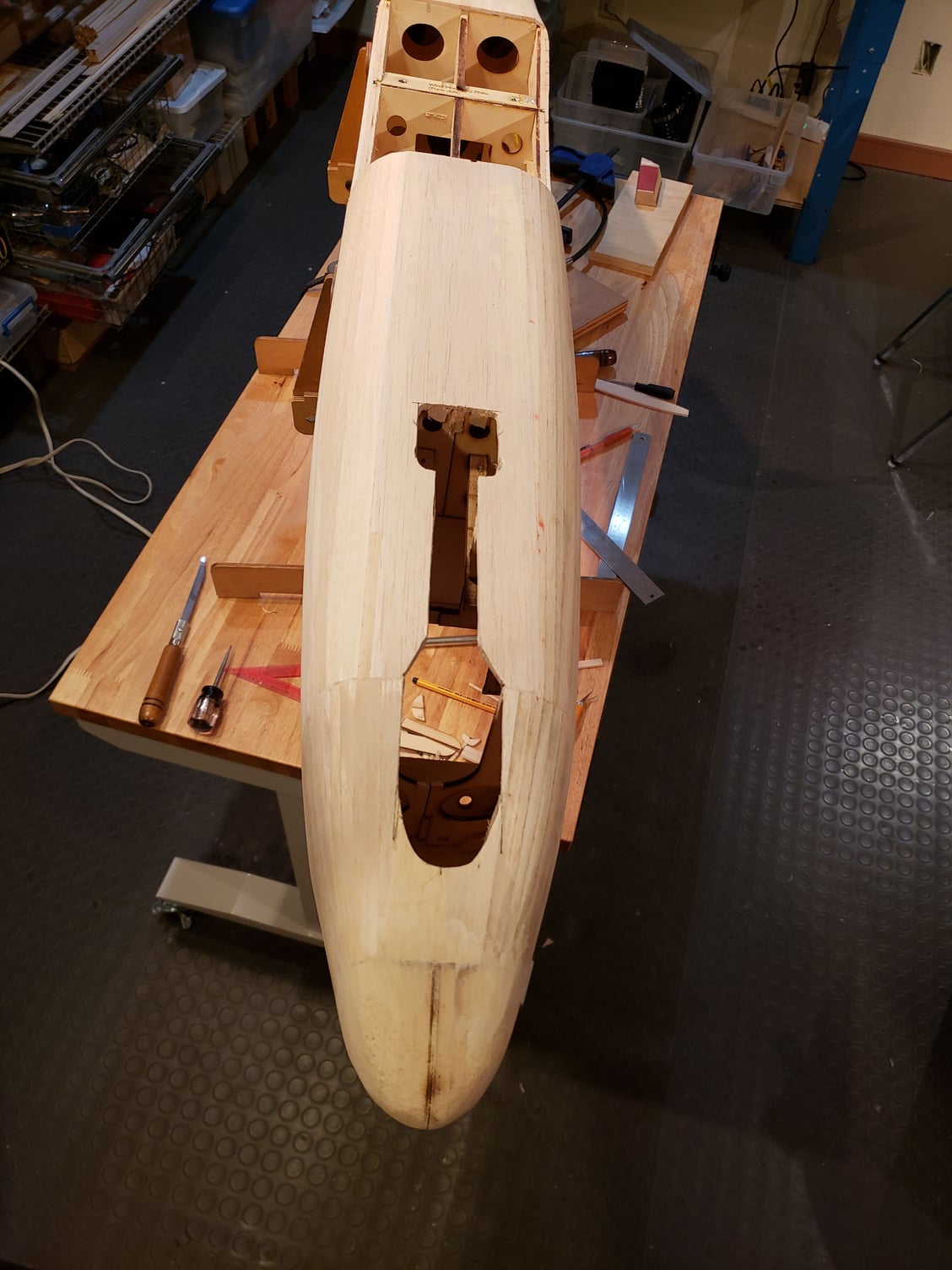
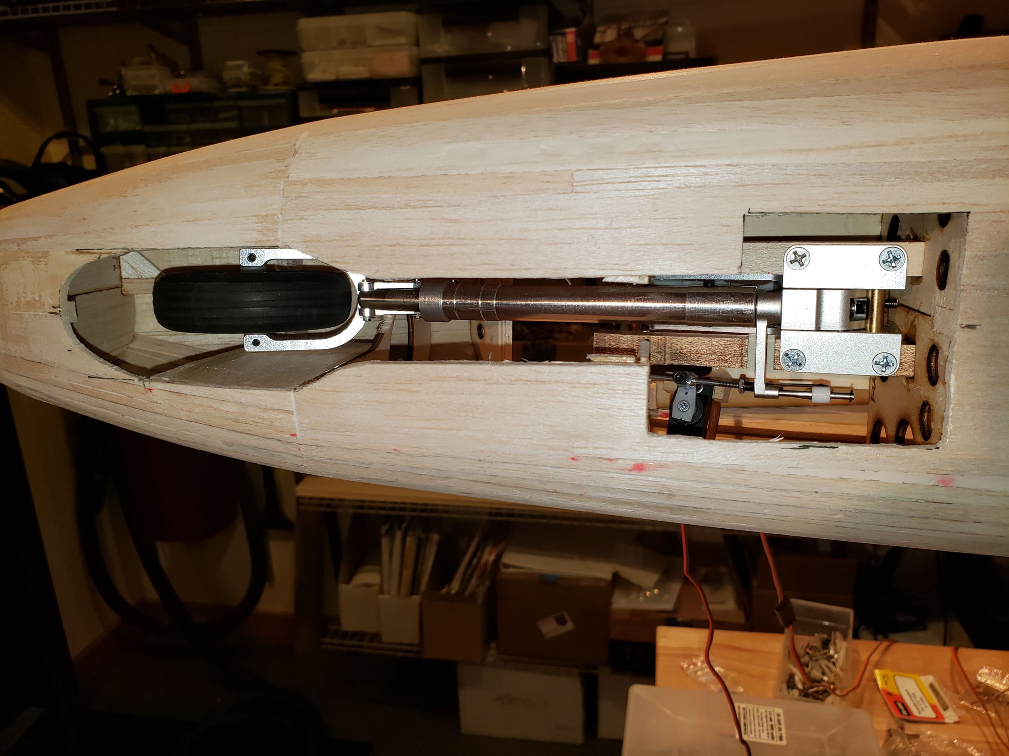
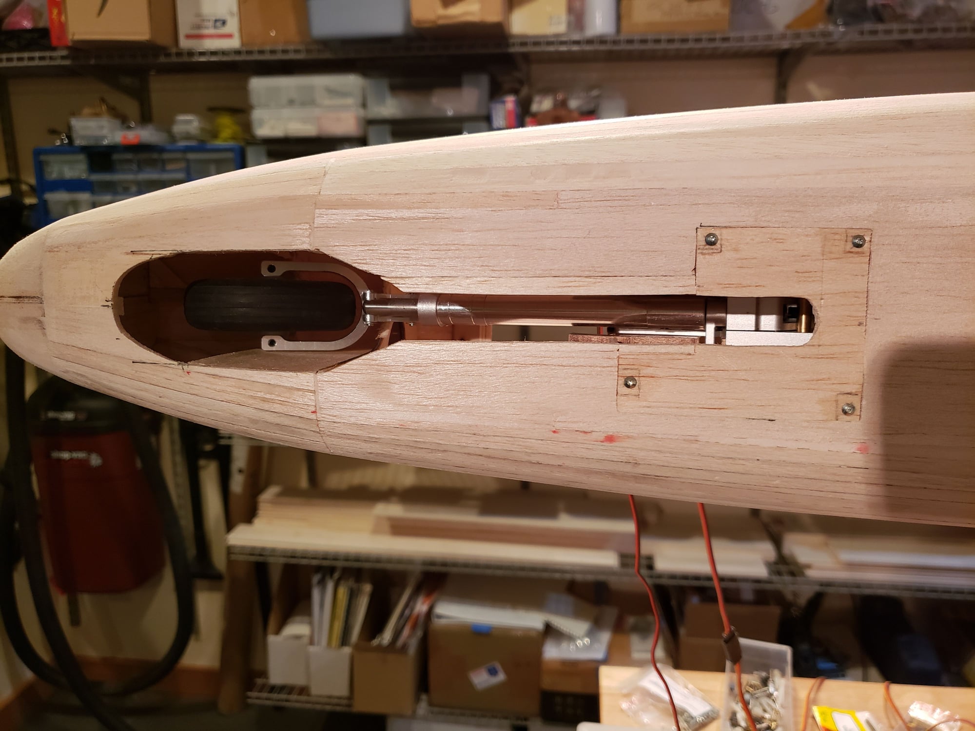
Installing the nose gear ... opened the bottom of the fuse to enable installation of the retract as the rails were installed during the fuse construction. The rails are angled at 10 degrees so that you can use a standard 90 degree retract and still get the slanted forward look of the Fenix nose gear. You can see a steering servo has been installed next to the nose gear and a hatch is in place to cover most of the opening.
 12-13-2023, 01:09 PM
#68
With holidays and travel work on the Fenix has been slow. But some progress to report ...
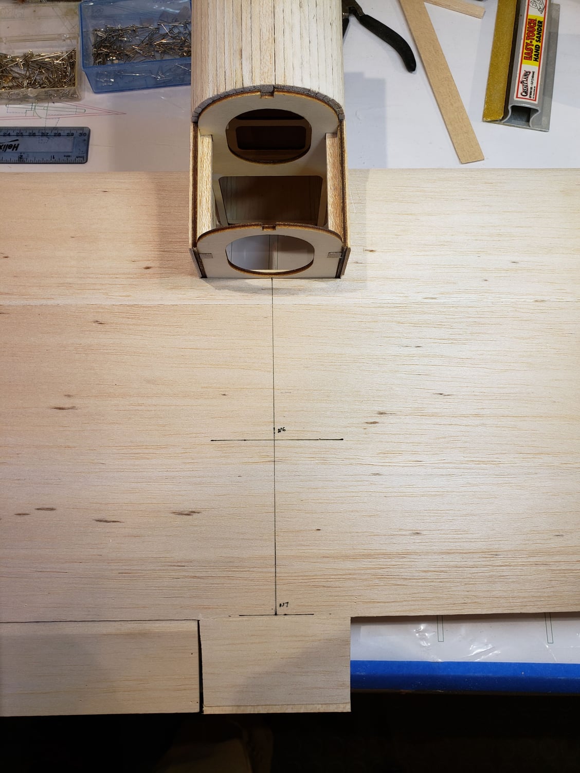
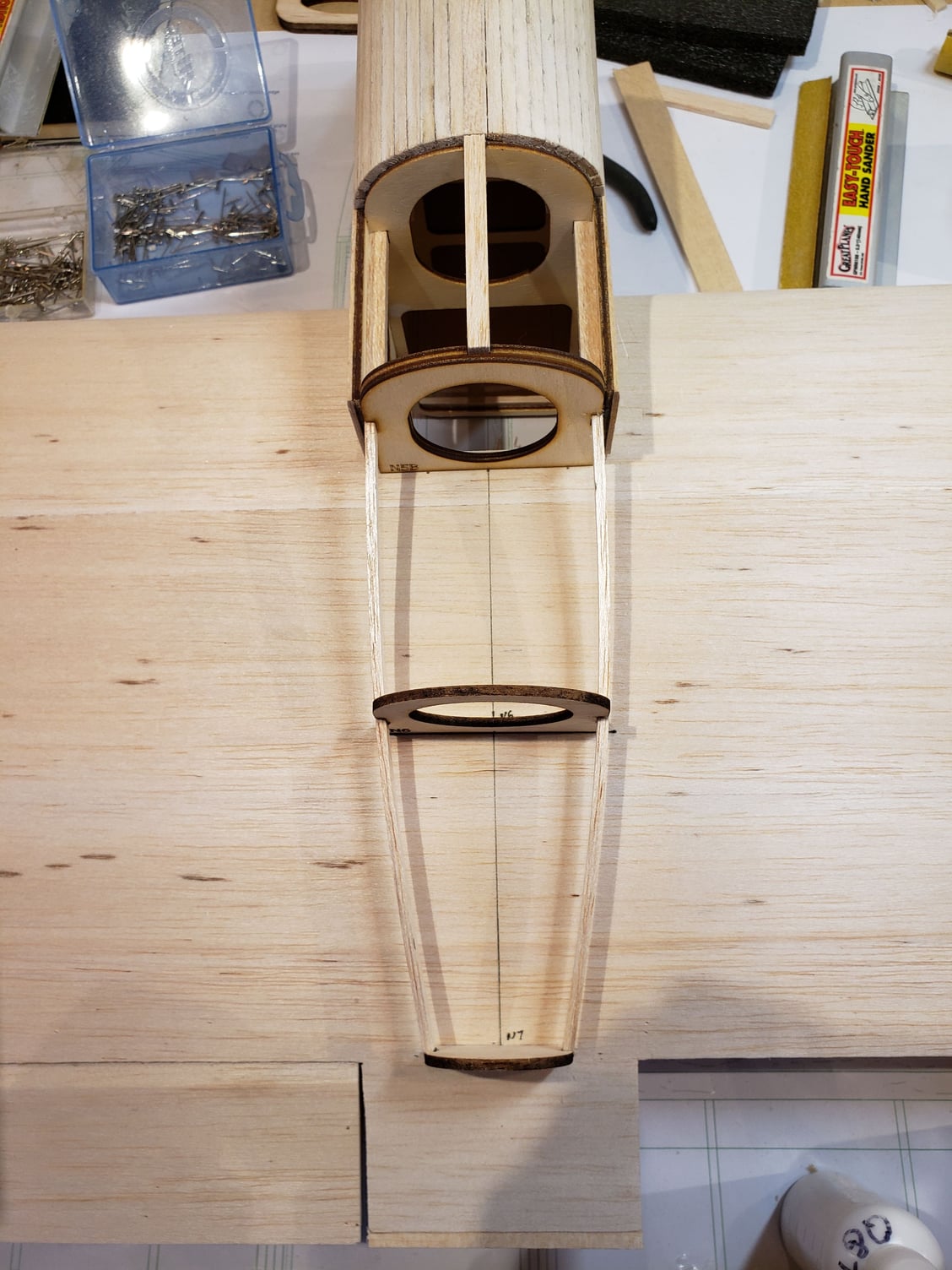
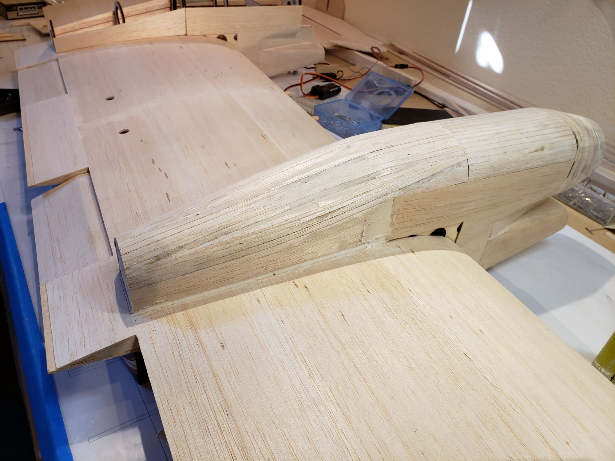
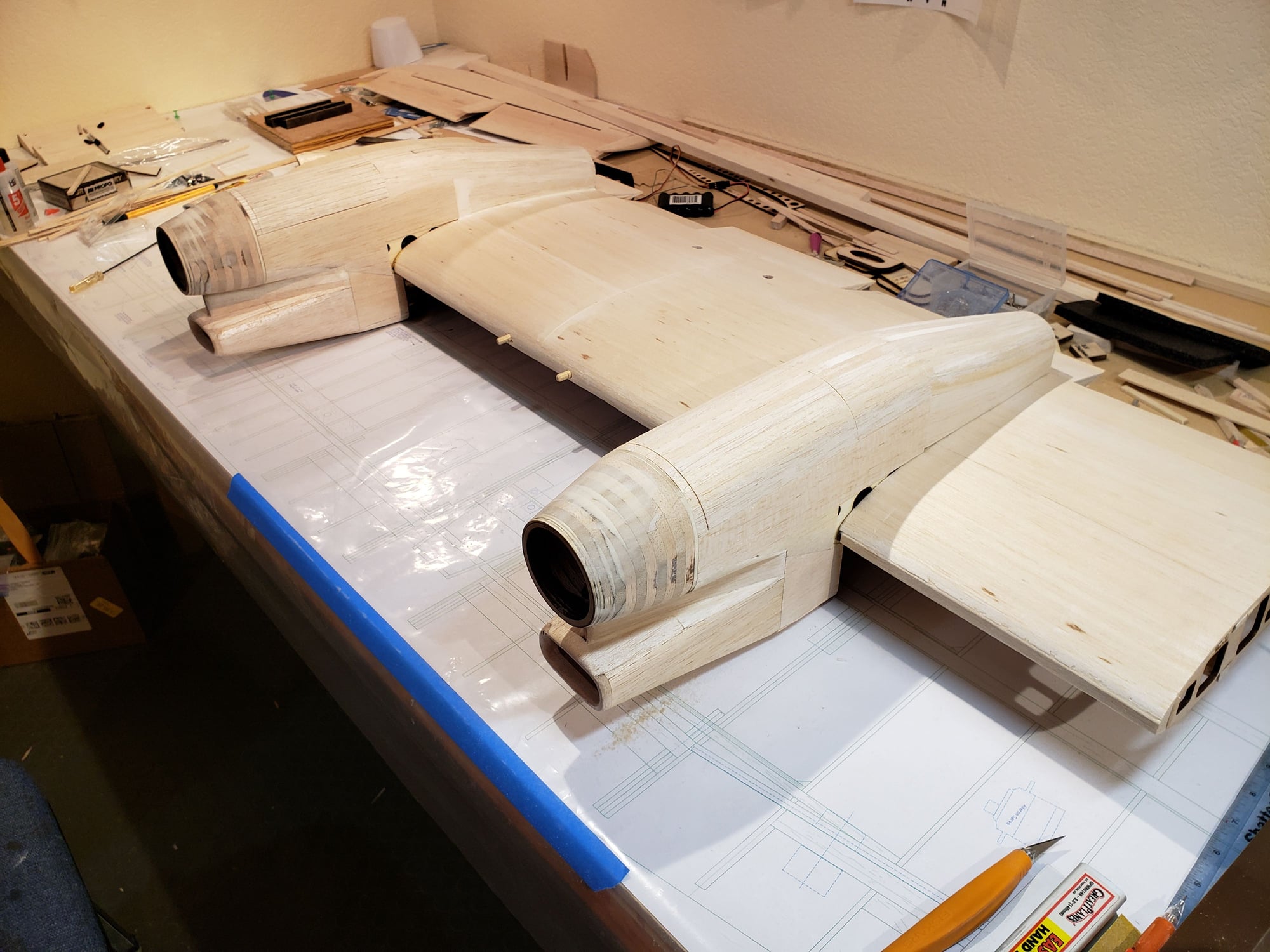
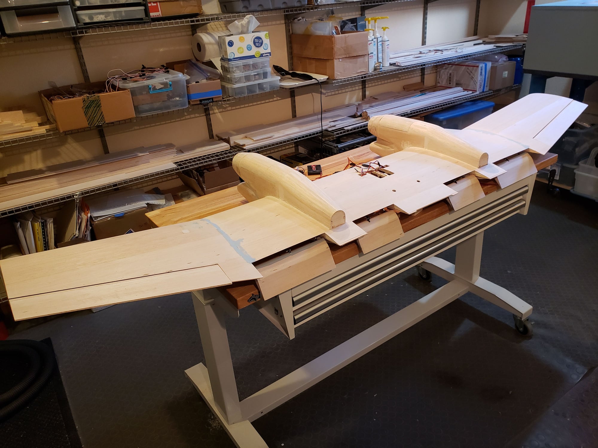
Assembly of the lower half of the nacelle. Put the formers in place and then sheet/plank around them all. Leave an opening for the gear to move
Assembly of the lower half of the nacelle. Put the formers in place and then sheet/plank around them all. Leave an opening for the gear to move
12-13-2023, 01:17 PM
#69
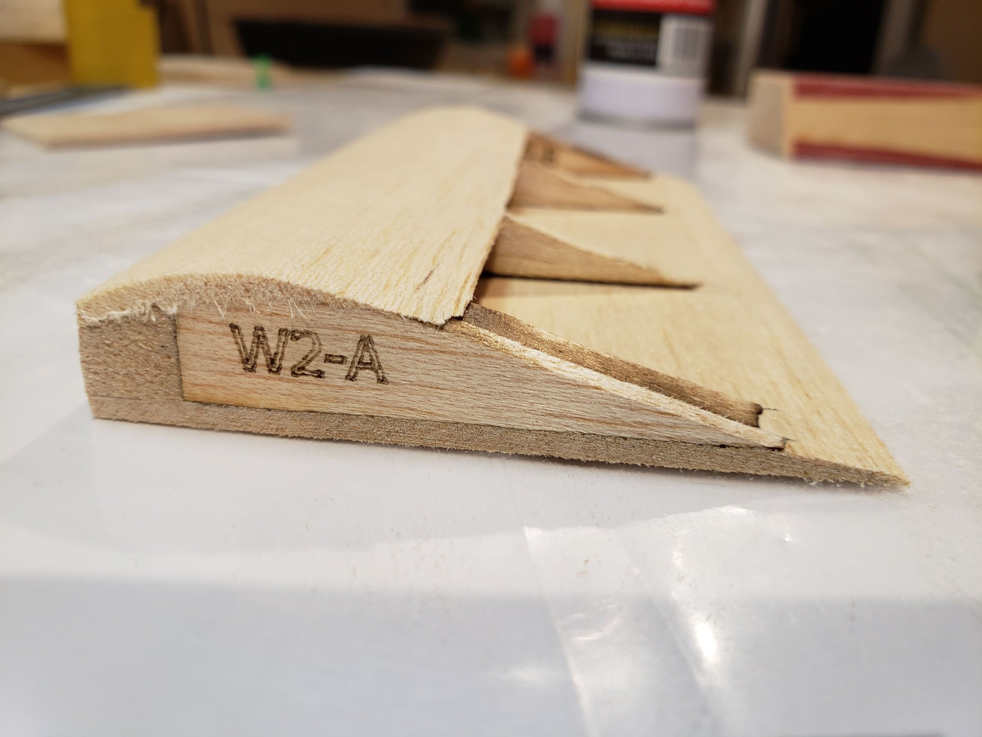
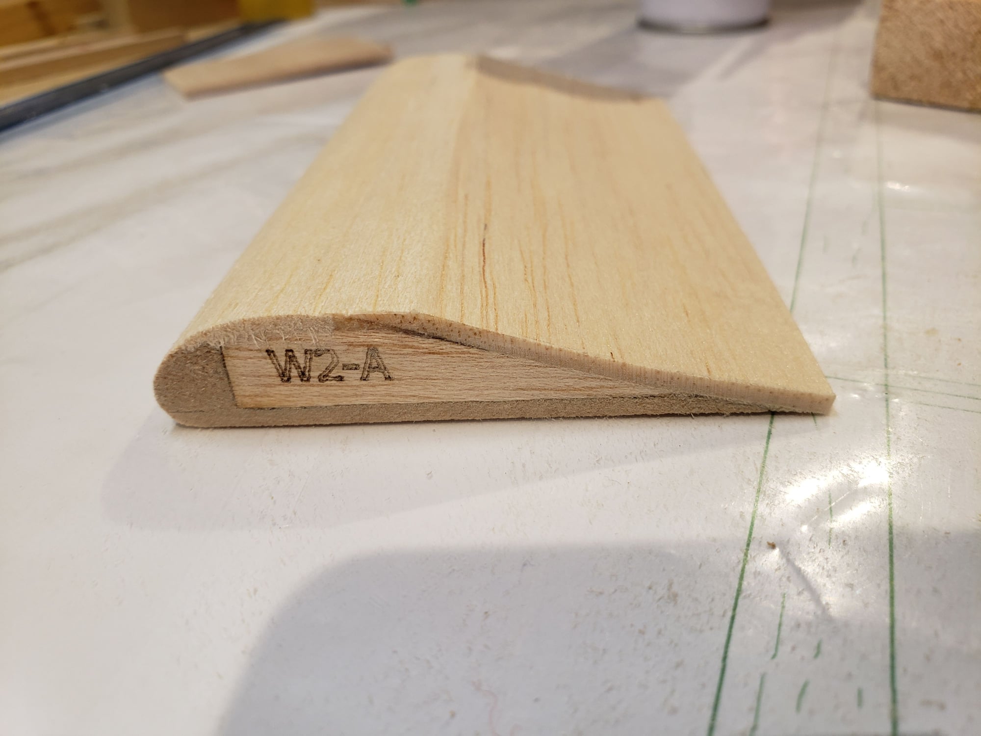
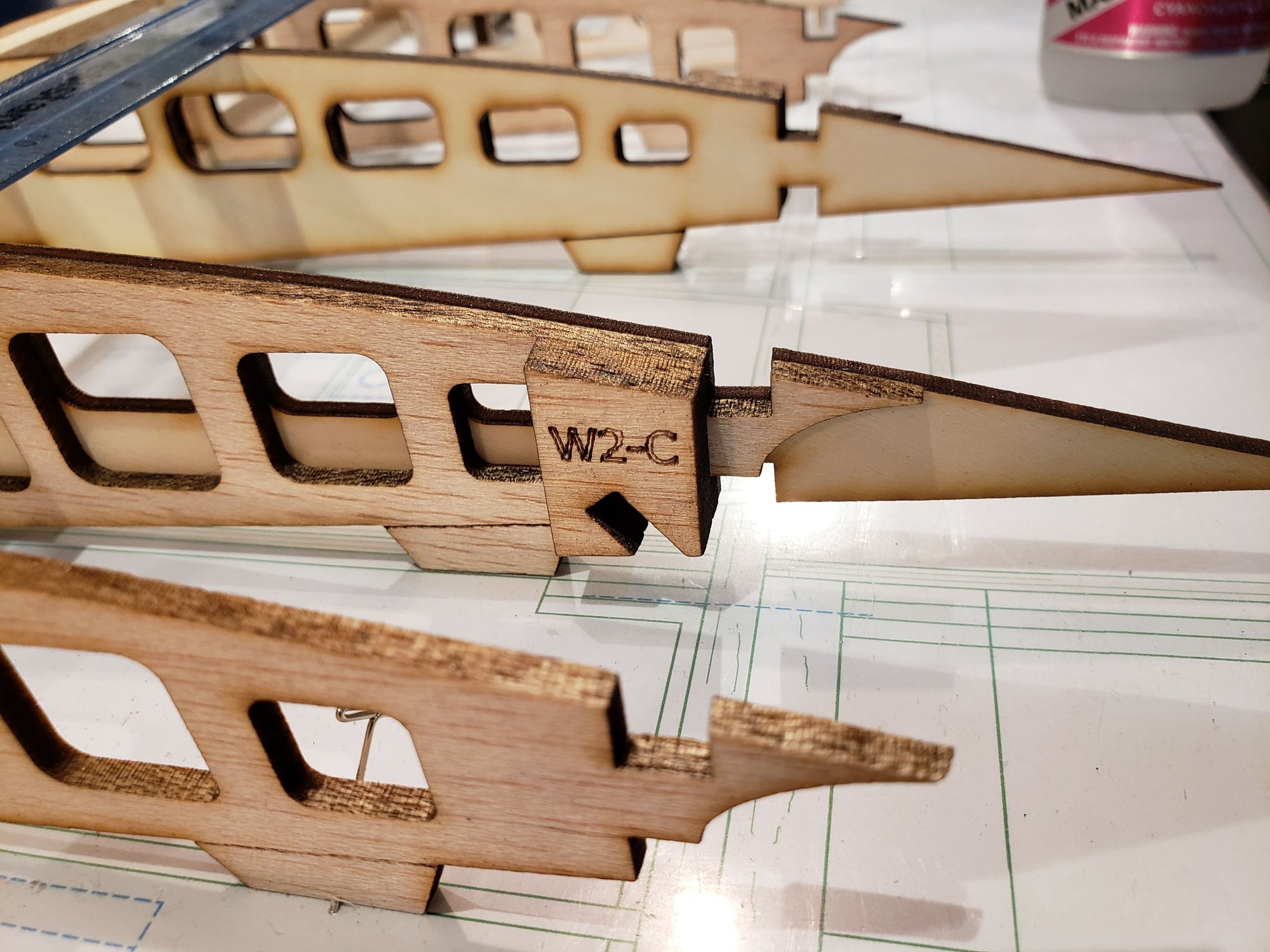
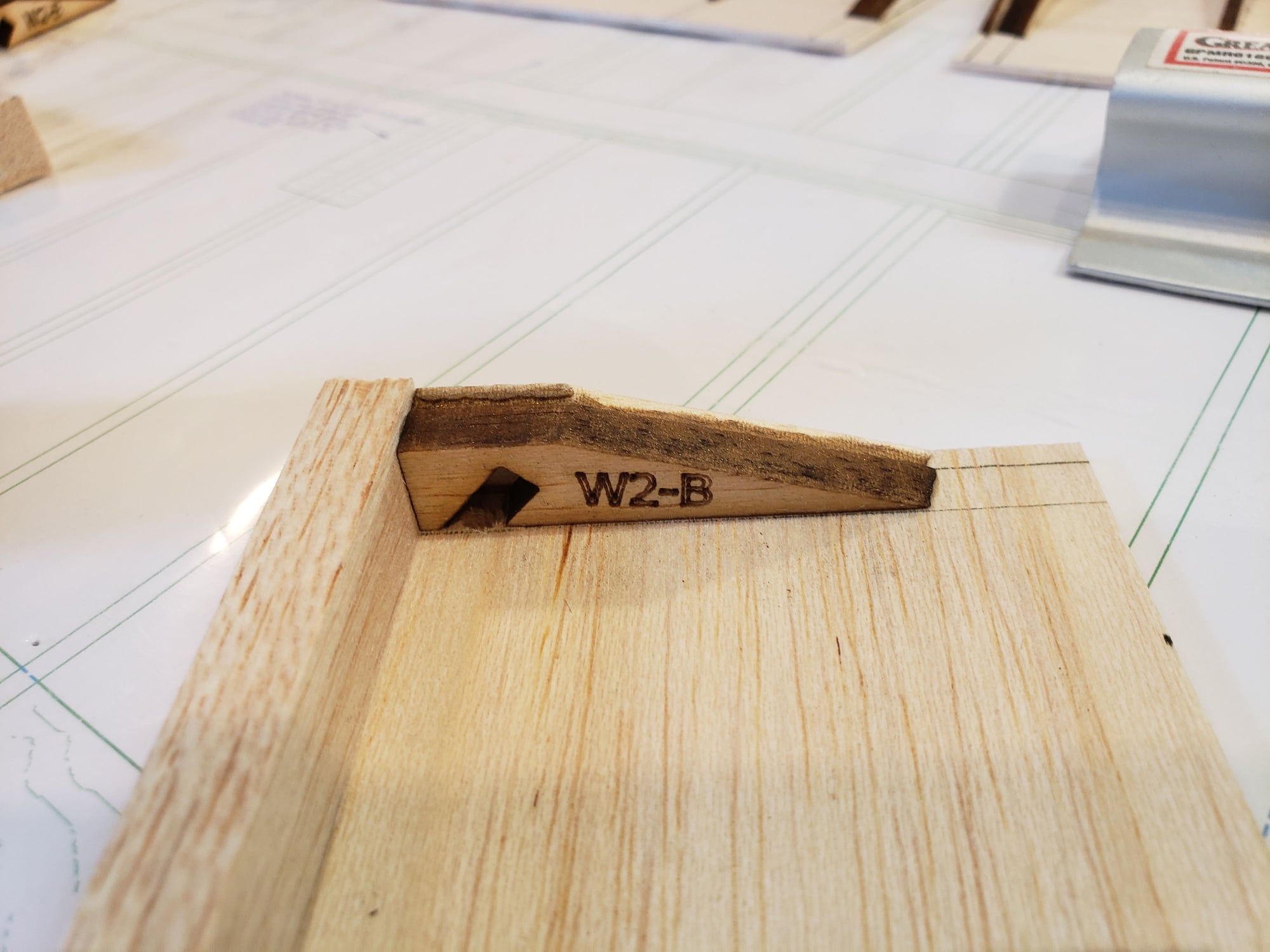
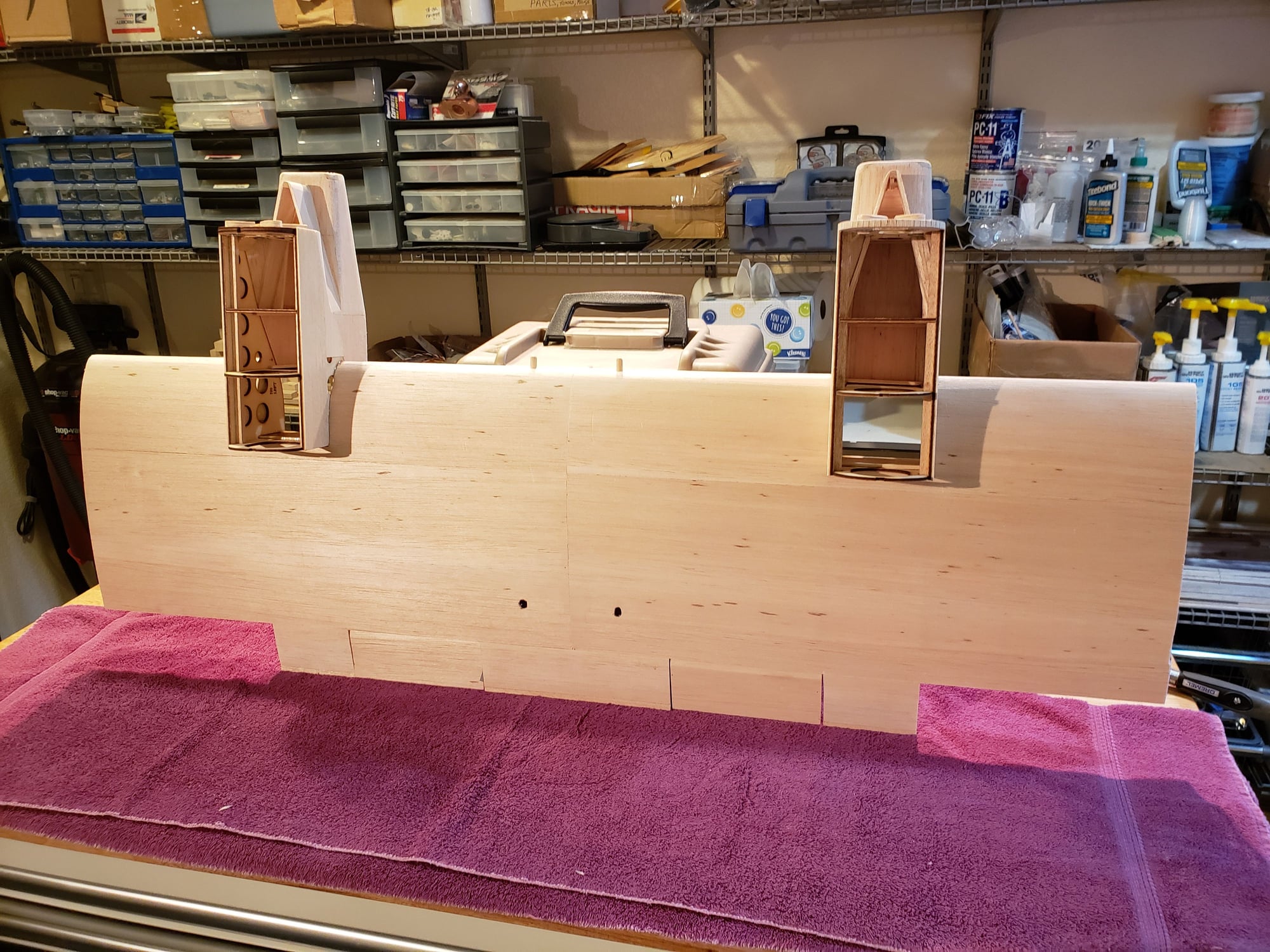
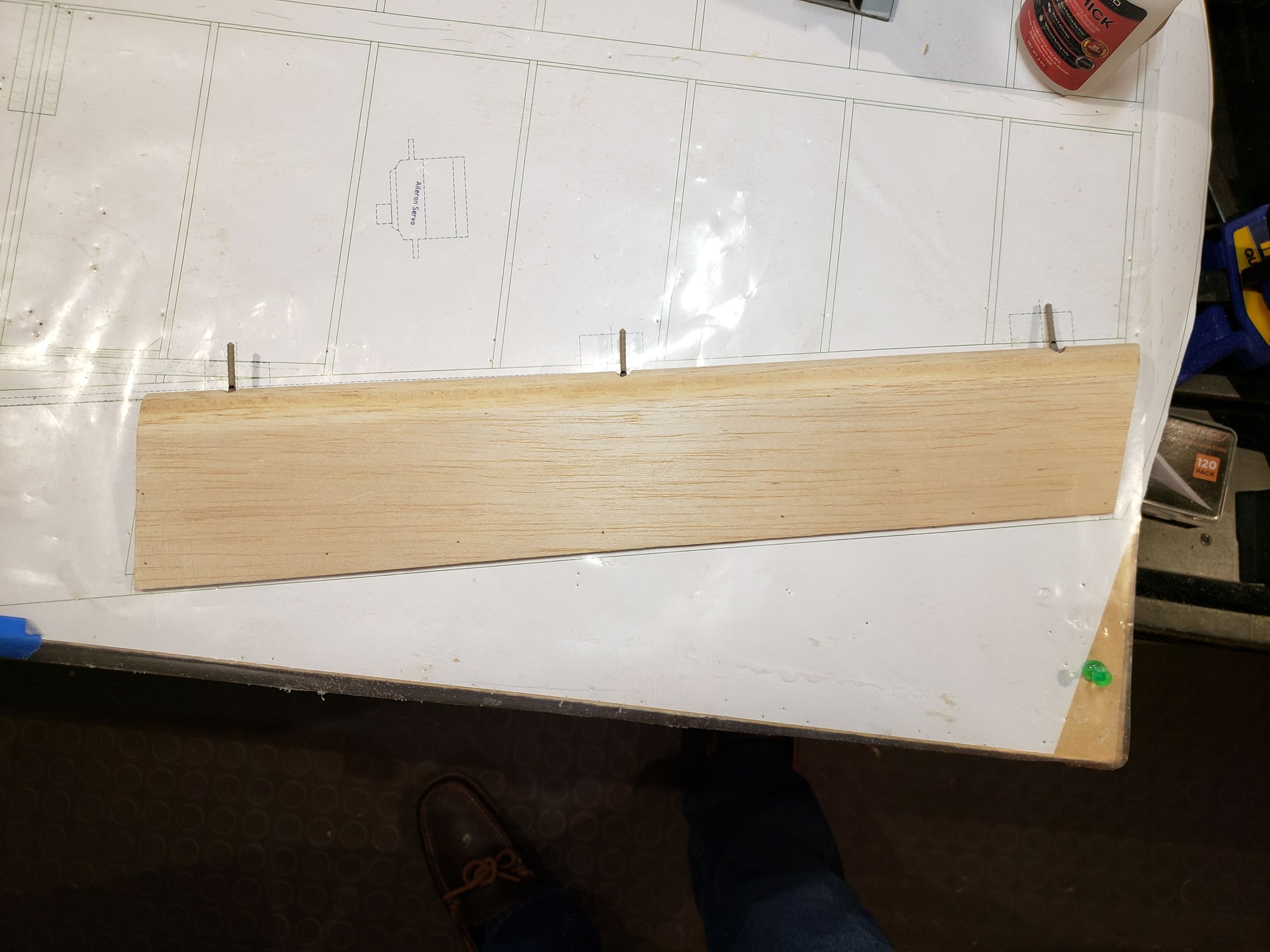
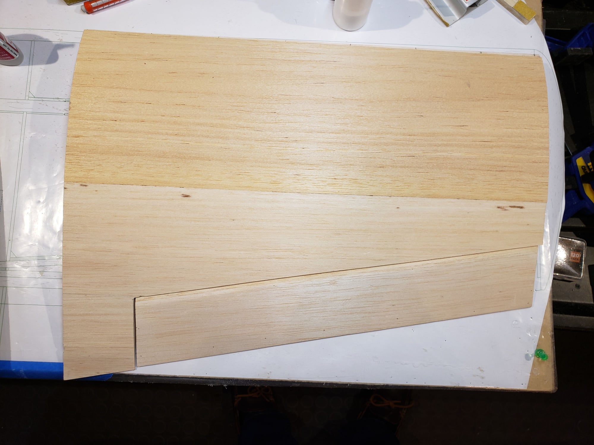
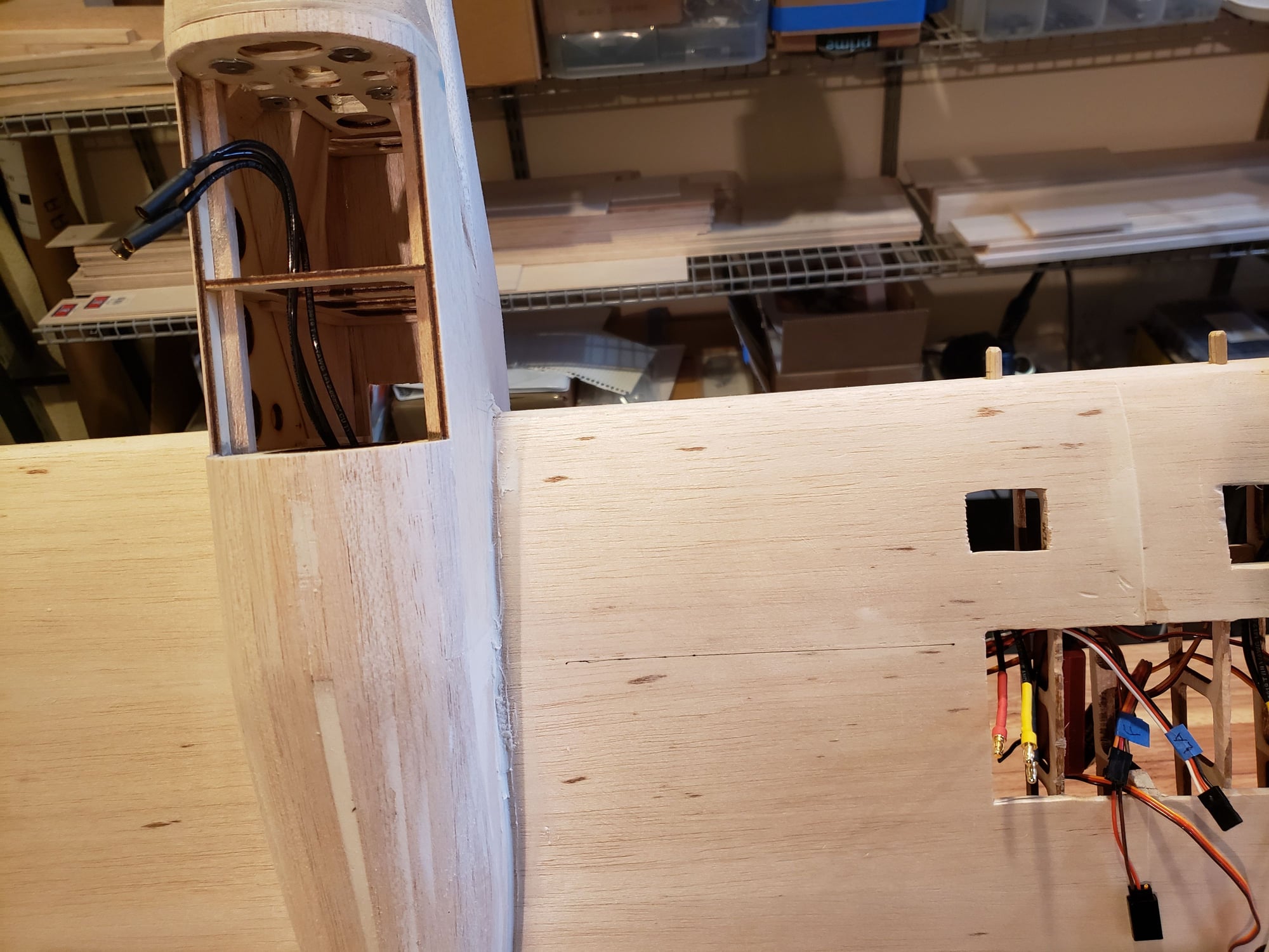
Building the outer wing panels is easy. Frame them up like the rest of the wing and sheet the top before removing from the plan.
Note the small piece of balsa just above the rear spar between the 2 left most ribs. This is a guide for the dihedral brace that's inserted when the wing is joined.
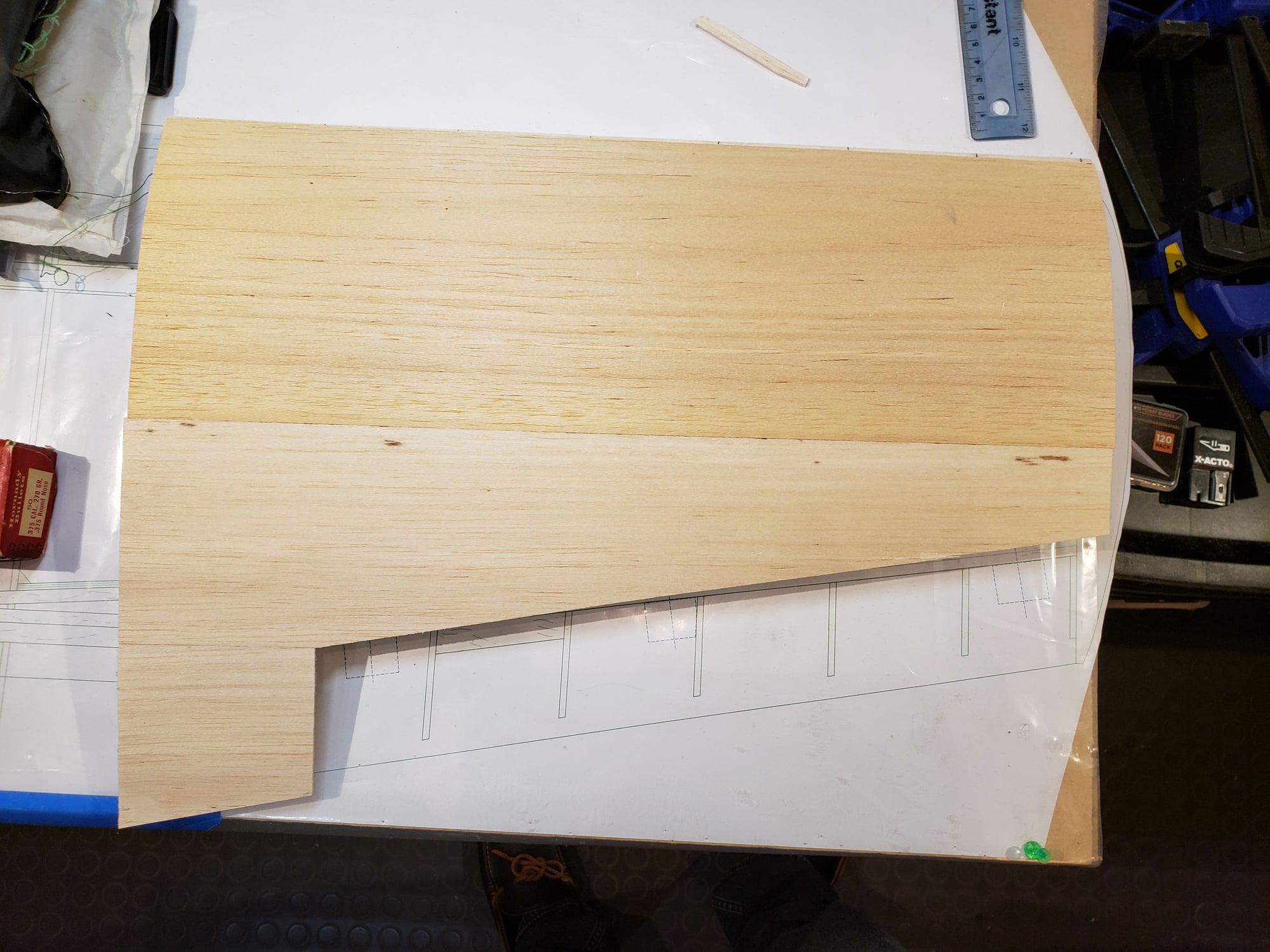
Note the small piece of balsa just above the rear spar between the 2 left most ribs. This is a guide for the dihedral brace that's inserted when the wing is joined.
12-13-2023, 01:21 PM
#70
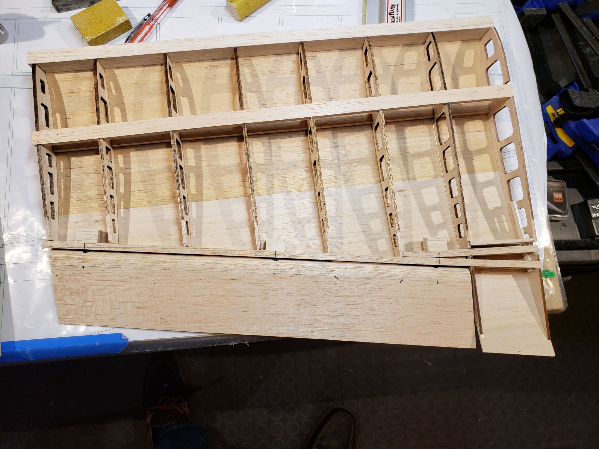
The aileron is built up in a series of steps per below.
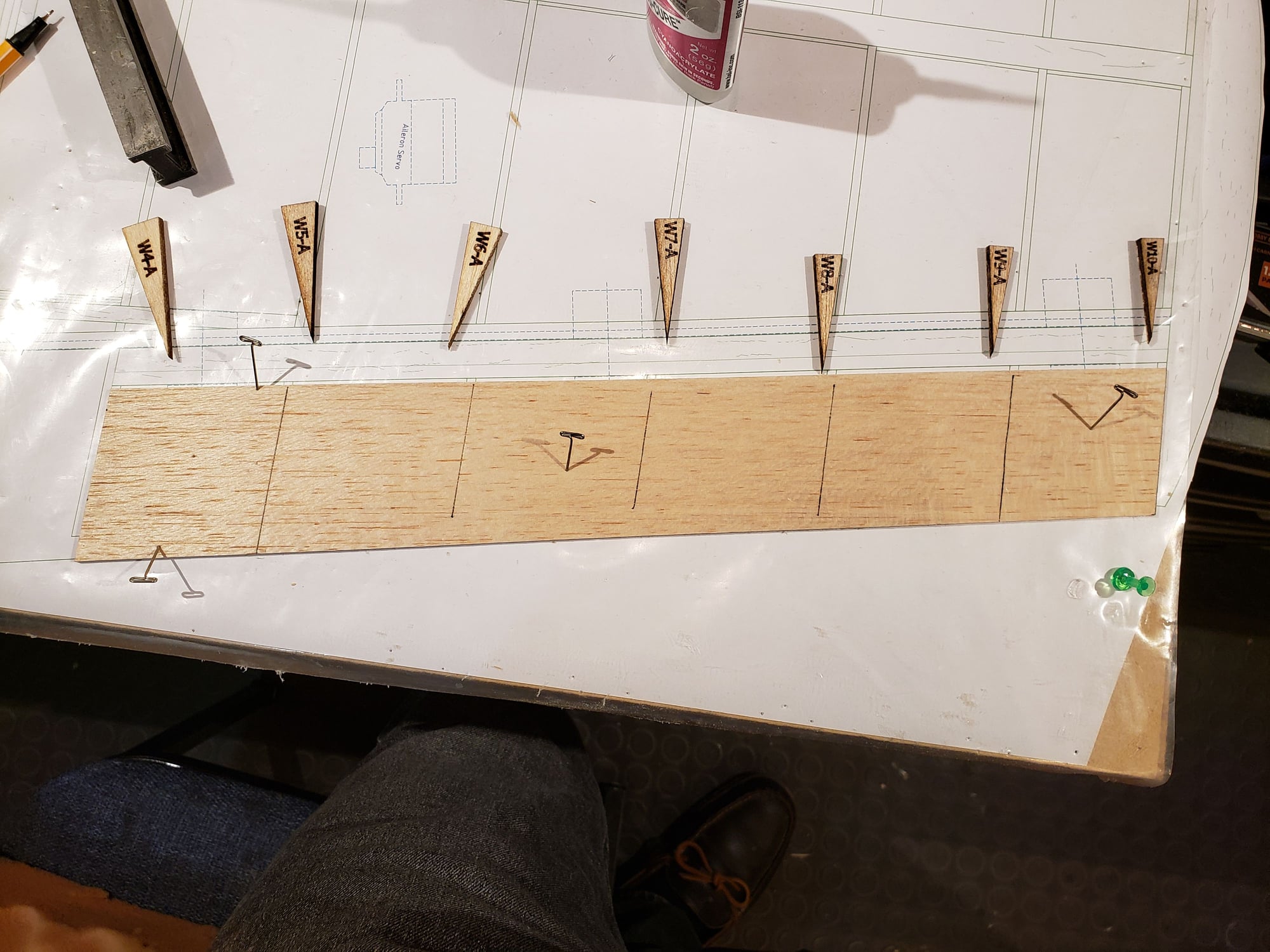
Cut bottom sheeting to size and lay out locations of the ribs.
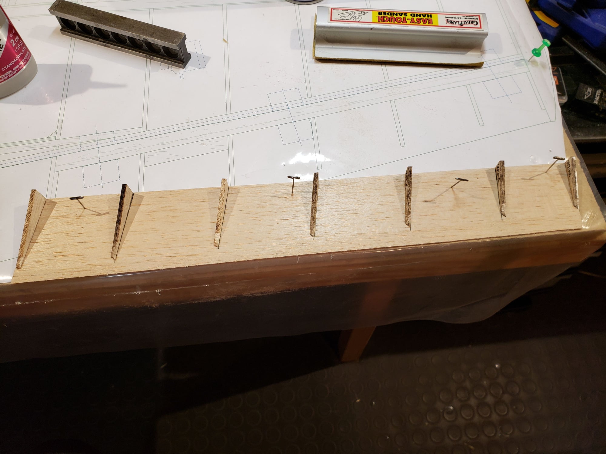
Glue in place.
Hard to see, but the trailing edge balsa is sanded to the same slope as the top of the ribs to facilitate adding the top sheeting.
Install hinge blocks and a ply mount for the control horn.
Add top sheeting and leading edge. Install pin hinges after sanding LE to shape.
Cut bottom sheeting to size and lay out locations of the ribs.
Glue in place.
Hard to see, but the trailing edge balsa is sanded to the same slope as the top of the ribs to facilitate adding the top sheeting.
Install hinge blocks and a ply mount for the control horn.
Add top sheeting and leading edge. Install pin hinges after sanding LE to shape.
12-13-2023, 01:25 PM
#71
Set up the aileron and associated servo.
Install hinge blocks and drill for pin hinges.
Installed!
Control horn in place and planning the location of the aileron servo.
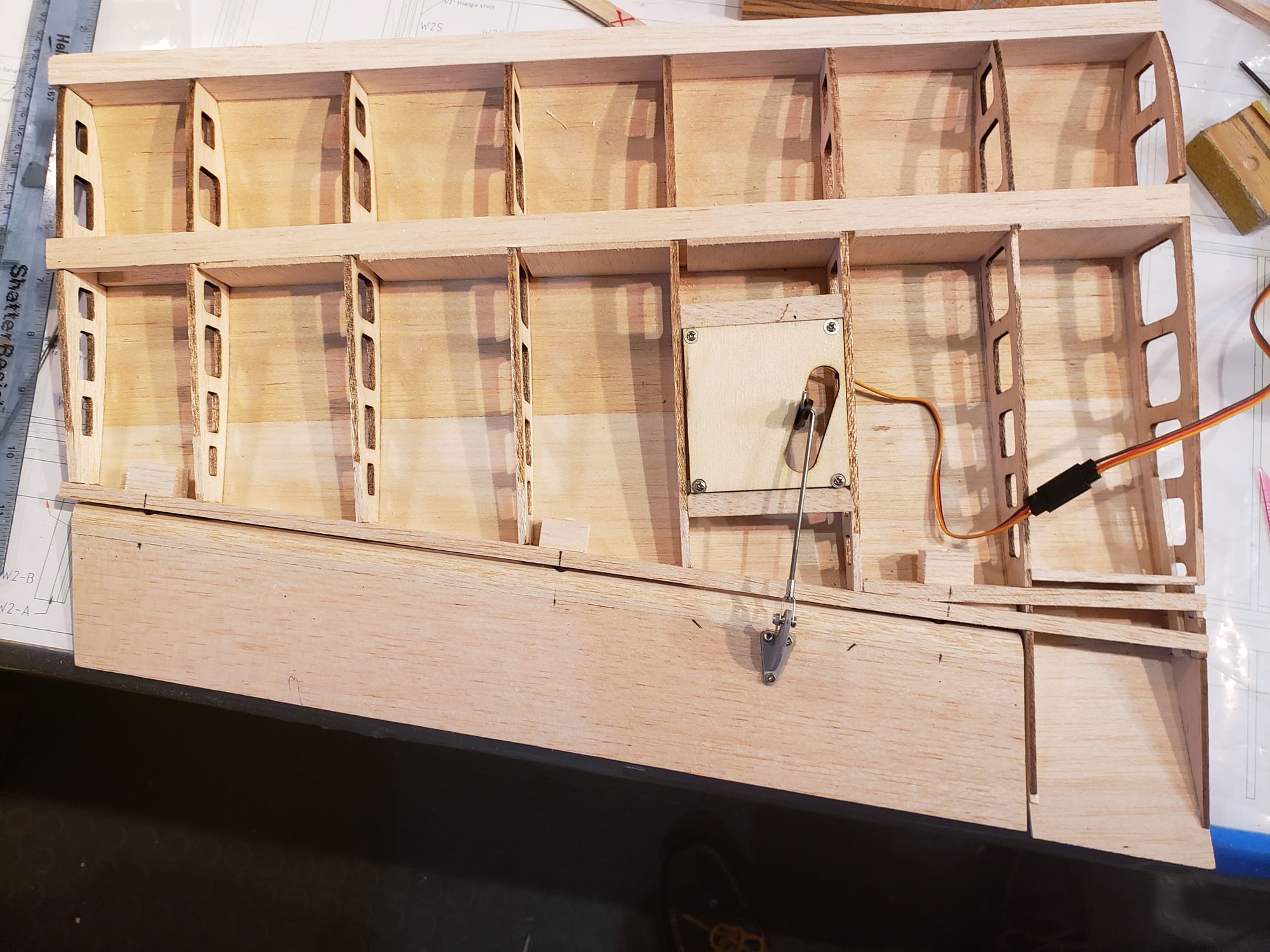
Aileron servo installed, connected, and functioning!
Install hinge blocks and drill for pin hinges.
Installed!
Control horn in place and planning the location of the aileron servo.
Aileron servo installed, connected, and functioning!
The following users liked this post:
jescardin (12-14-2023)
12-28-2023, 09:21 AM
#72
Slow progress through the holidays ... starting to get back in the swing of things.
Adding the outer wing panels requires setting up the 4 dihedral braces and aligning the inner and outer panels. The braces are different for the top and bottom as the respective angles are slightly different. Slow cure epoxy should be used to completely coat the braces where they join the spar and then assemble and clamp all together.
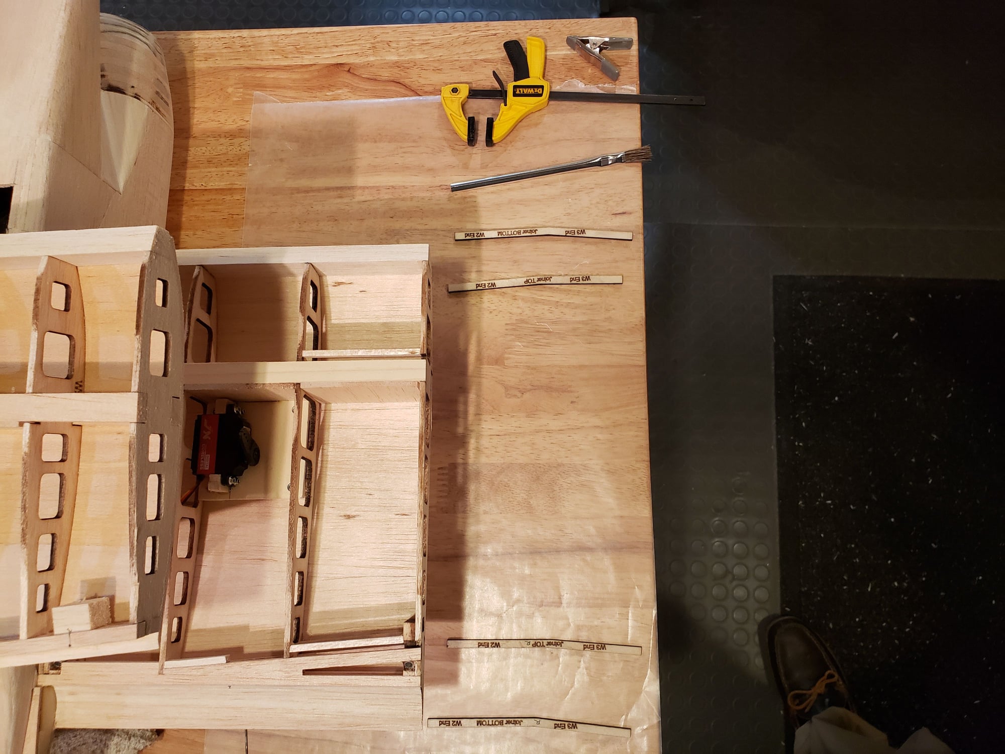
Adding the outer wing panels requires setting up the 4 dihedral braces and aligning the inner and outer panels. The braces are different for the top and bottom as the respective angles are slightly different. Slow cure epoxy should be used to completely coat the braces where they join the spar and then assemble and clamp all together.
01-04-2024, 04:37 PM
#73
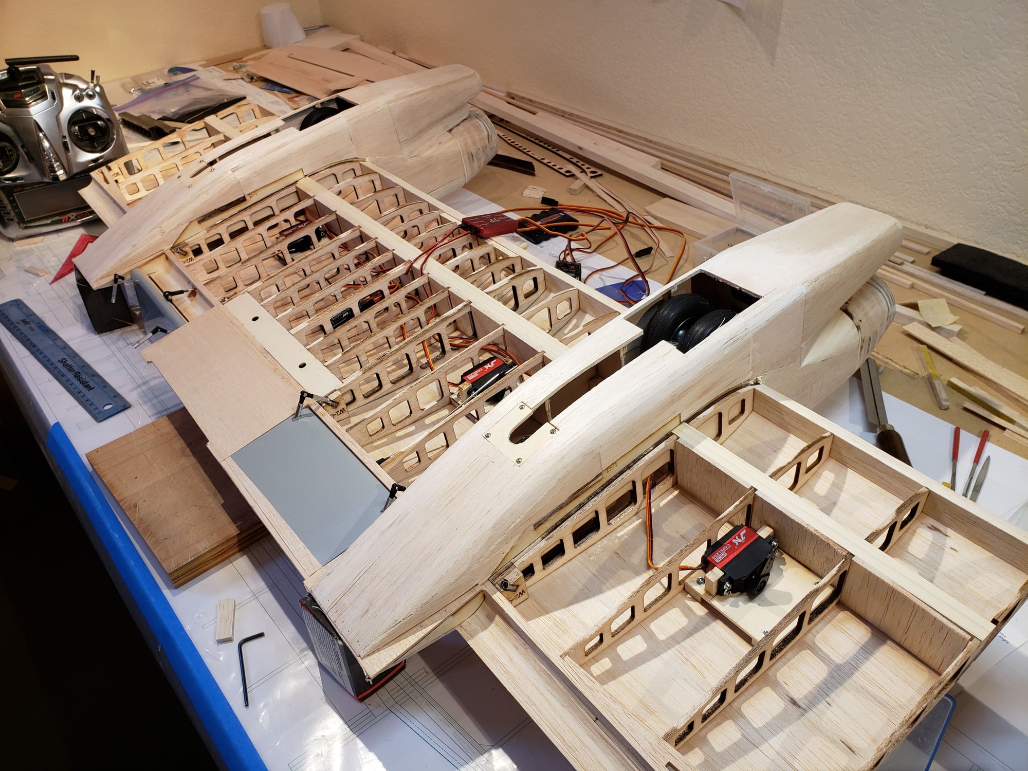
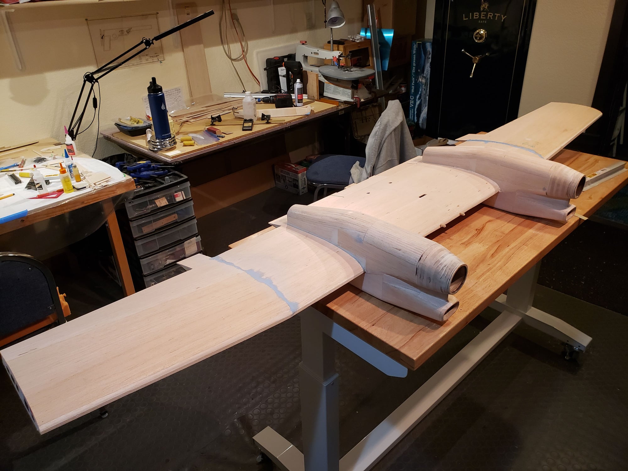
With the wing joined, it's time to complete the flaps. The outer flap section had to wait till the panel was added to be able to align the TE of the flap properly. Once done, I did a basic setup on the JR Matchbox for flap travel. The 2nd & 3rd pic shows the flaps WAY DOWN ... more than needed. The max for landing would be 40 degrees.
01-04-2024, 04:53 PM
#74
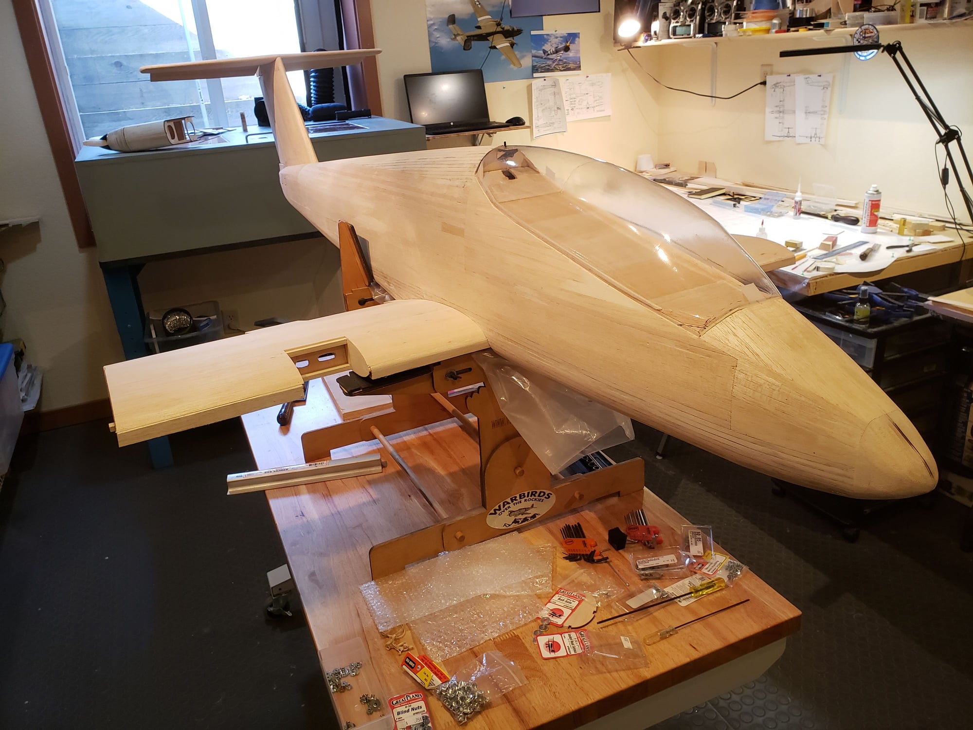
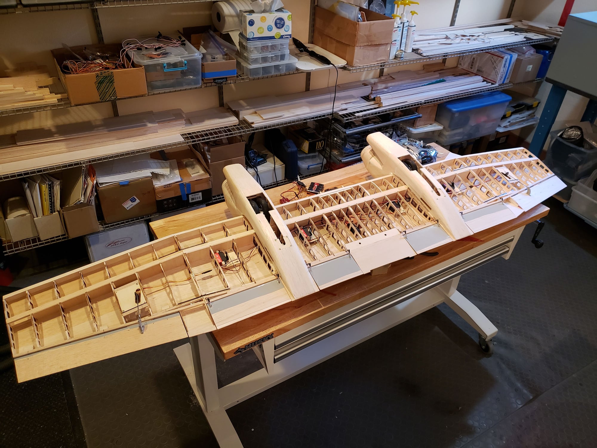
Wiring up the motors. With batteries in the fuse and motors in the nacelles, it's obvious to the casual observer that there will need to be an extension. In this case, about 18". Originally I was going to put the ESC in the nacelle. This means putting the extension on the battery side. While that can be done, capacitors need to be added on the extension near the ESC to manage the changing current loads. I opted to extend the motor side wires. The ESC will be mounted to the top of the wing and receive cooling airflow. I've opted for bullet connectors at each end of the extension for flexibility. Once this is all working it could be optimized to remove a set.
So the setup will look something like this ...
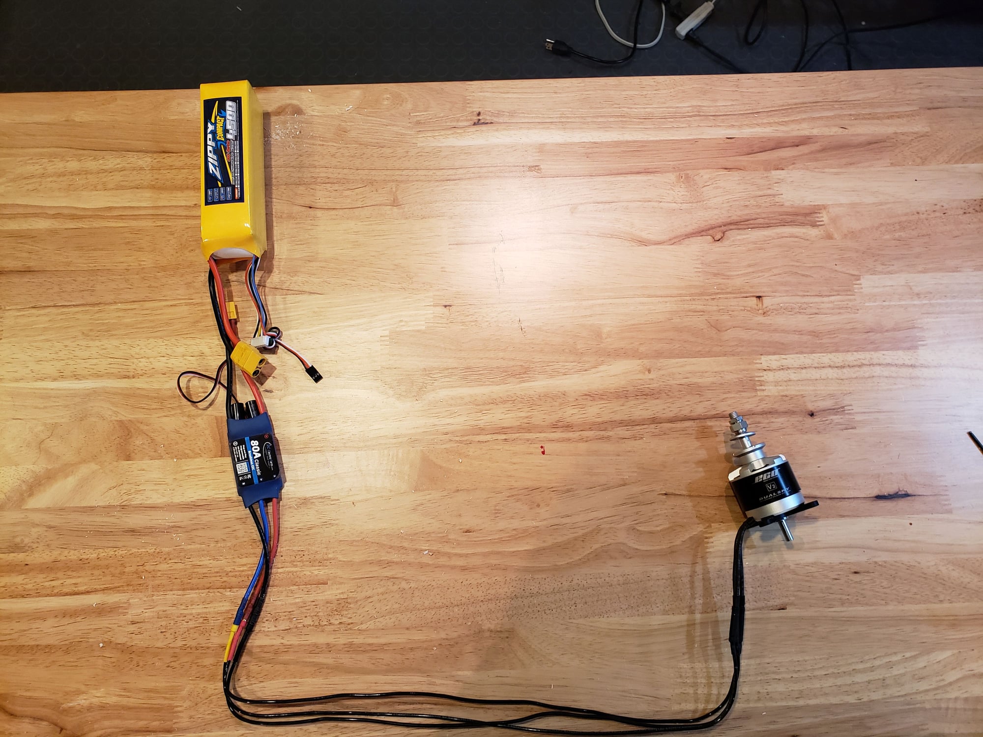
Battery is NOT plugged in
Extension wires in the wing
So the setup will look something like this ...
Battery is NOT plugged in
Extension wires in the wing