


IA-58H Pucara Fenix Custom Plan and Build
 09-03-2023, 01:30 PM
#1
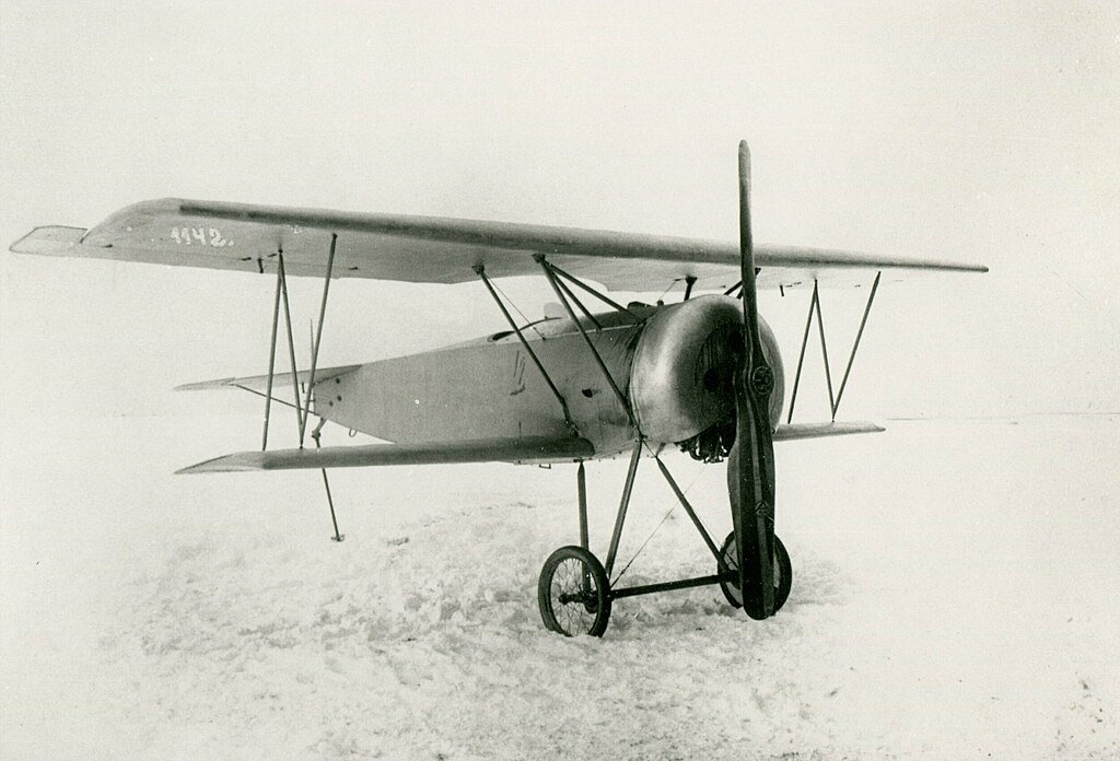
I'm starting a new project to build a 1/7 scale IA-58H Pucara Fenix (Argentinian, designed and built by FMA). The Fenix is the latest variant of the Pucara, whose design dates back to the late 1960's. The general design does not stand up to current needs for light attack aircraft, thus the Fenix is being developed for a COIN or COunter INsurgency role. It has many upgrades to areas like avionics, sensors, weapons, and most notably engines. The engine upgrade materially changes the cowling and gives the plane a distinctively more aggressive look. At lease in my opinion 
A couple of shots here where you can see the difference.
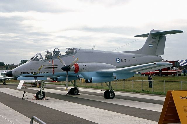
IA-58A
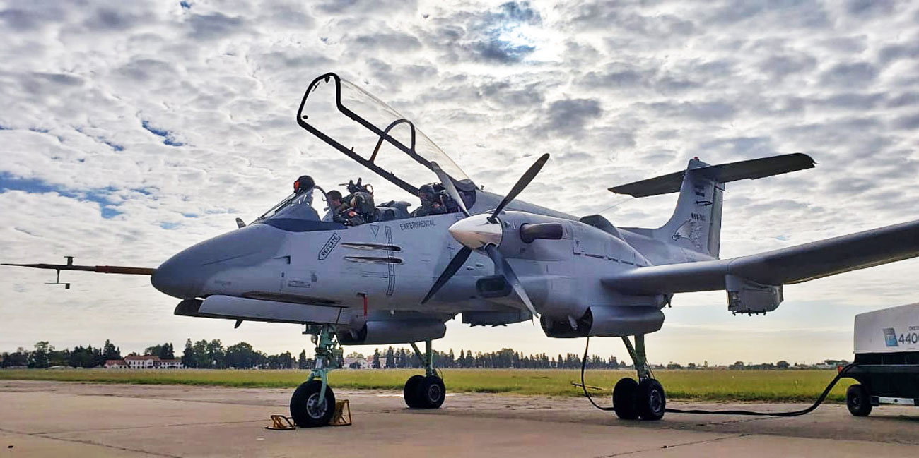
IA-58H
A couple of shots here where you can see the difference.
IA-58A
IA-58H
 09-03-2023, 01:39 PM
#2
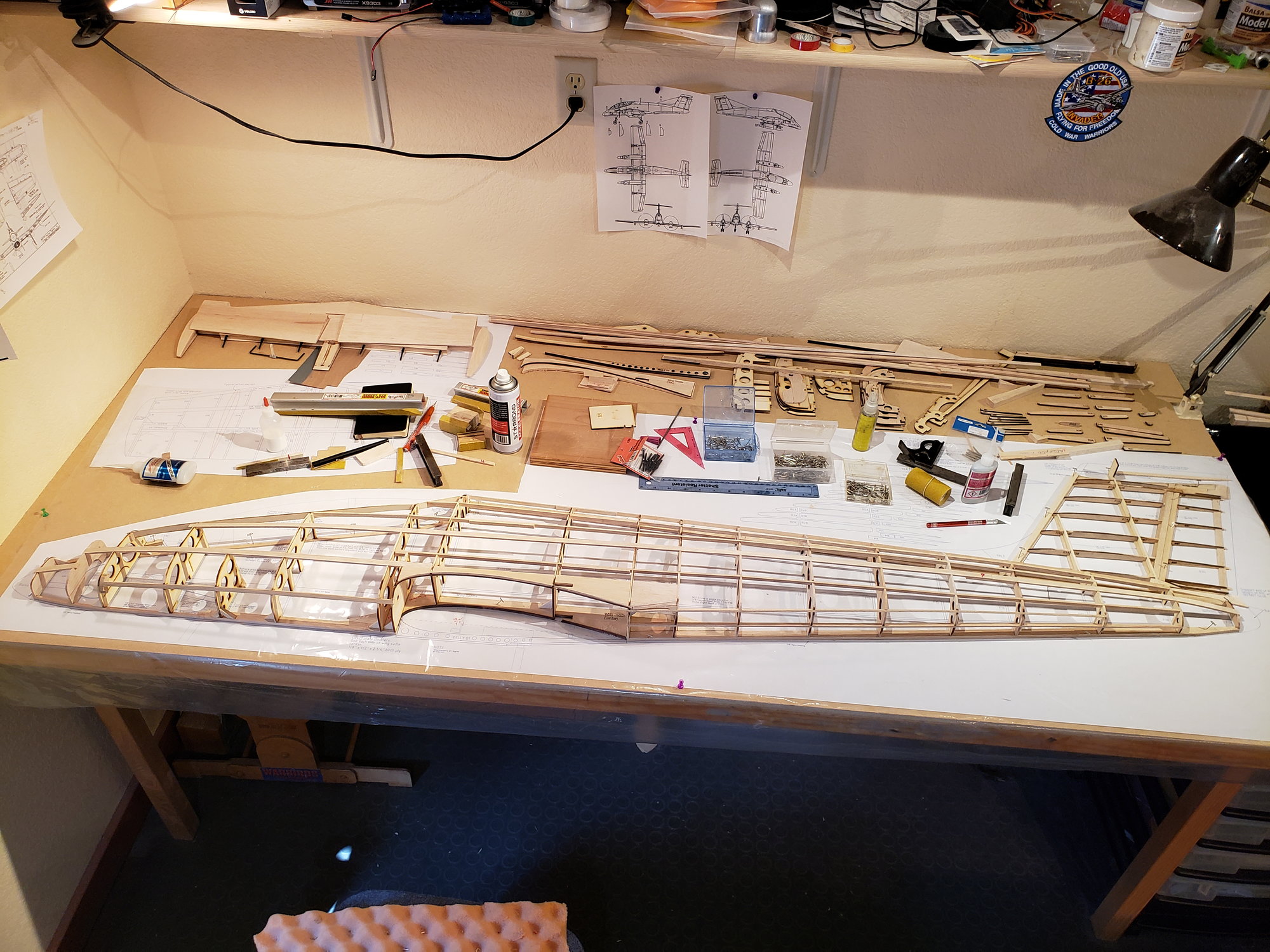
As there are no kits or plans for the Fenix variant or in the size I'm looking for, I've decided to draw my own. Drawing the plans was quite a journey in and of itself, probably worthy of it's own thread, but we'll focus on the build here.
My goal in drawing the plan was to keep the aircraft as scale as possible, but still relatively easy to fly. To that end the one change I've made to to increase the wing area by 12%.
Wing Span: 2,061 mm (81")
Wing Area: 636,866 sq mm (987 sq")
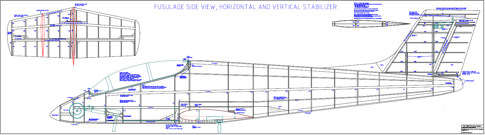
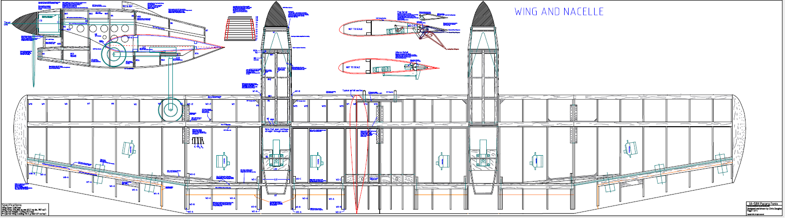
These are the rough plans.
My goal in drawing the plan was to keep the aircraft as scale as possible, but still relatively easy to fly. To that end the one change I've made to to increase the wing area by 12%.
Wing Span: 2,061 mm (81")
Wing Area: 636,866 sq mm (987 sq")
These are the rough plans.
09-03-2023, 02:05 PM
#3
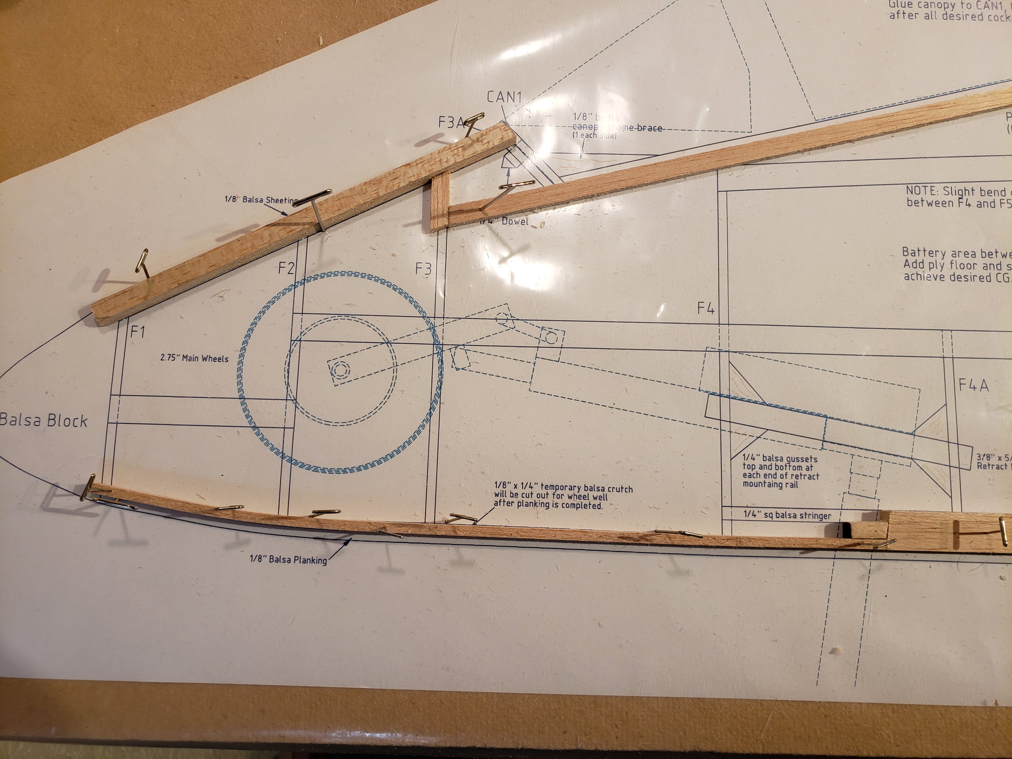
One concern I had with drawing my own plans was to ensure the plane would be stable in flight. While the plan is obviously of an existing and successful design, we all know that not everything scales. While the Fenix has a generous V-stab and H-stab there is also a LOT of area ahead of the CG in both the fuse and the 2 engine nacells. The Fenix increased this area over the previous engine cowling designs.
I used eCalc for the initial analysis, putting in all the relevant dimensions including aspects of the fuse. It came back with a CG 25.50 ... 30.50% of MAC, OK, that's good. eCalc also indicated that the H-stab is sufficiently large for stable flight and that the fuse would not effect it negatively. effect it.
All that said, I wanted further confirmation that the design would be stable. I built a 1/4 scale model of my 1/7 scale model as a hand launched glider. I used the CG from eCalc. I'm quite pleased with how well this glider flies. It's quite stable. I moved the CG back to 35-40% MAC and it still flies great.
09-03-2023, 02:13 PM
#4
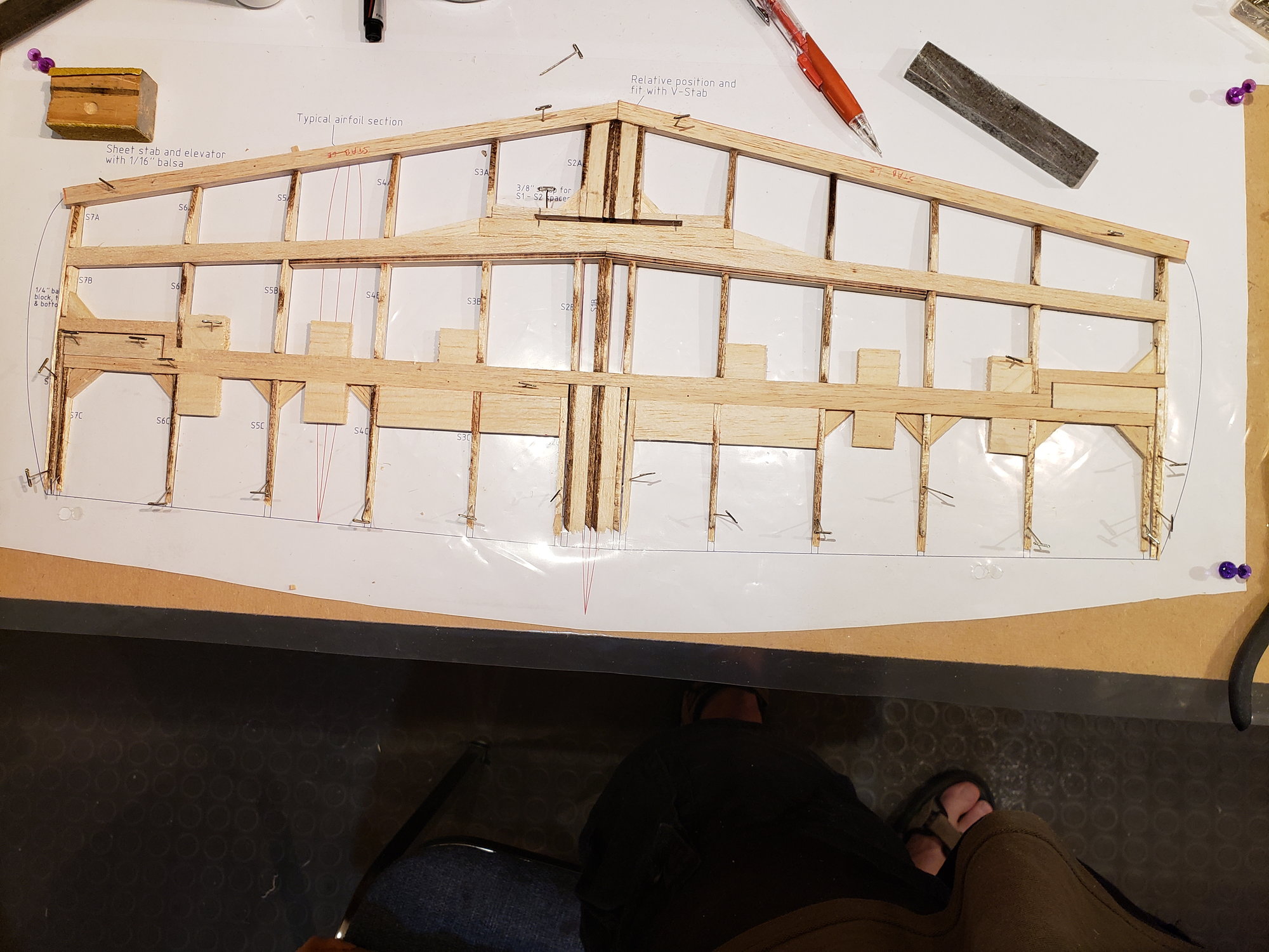
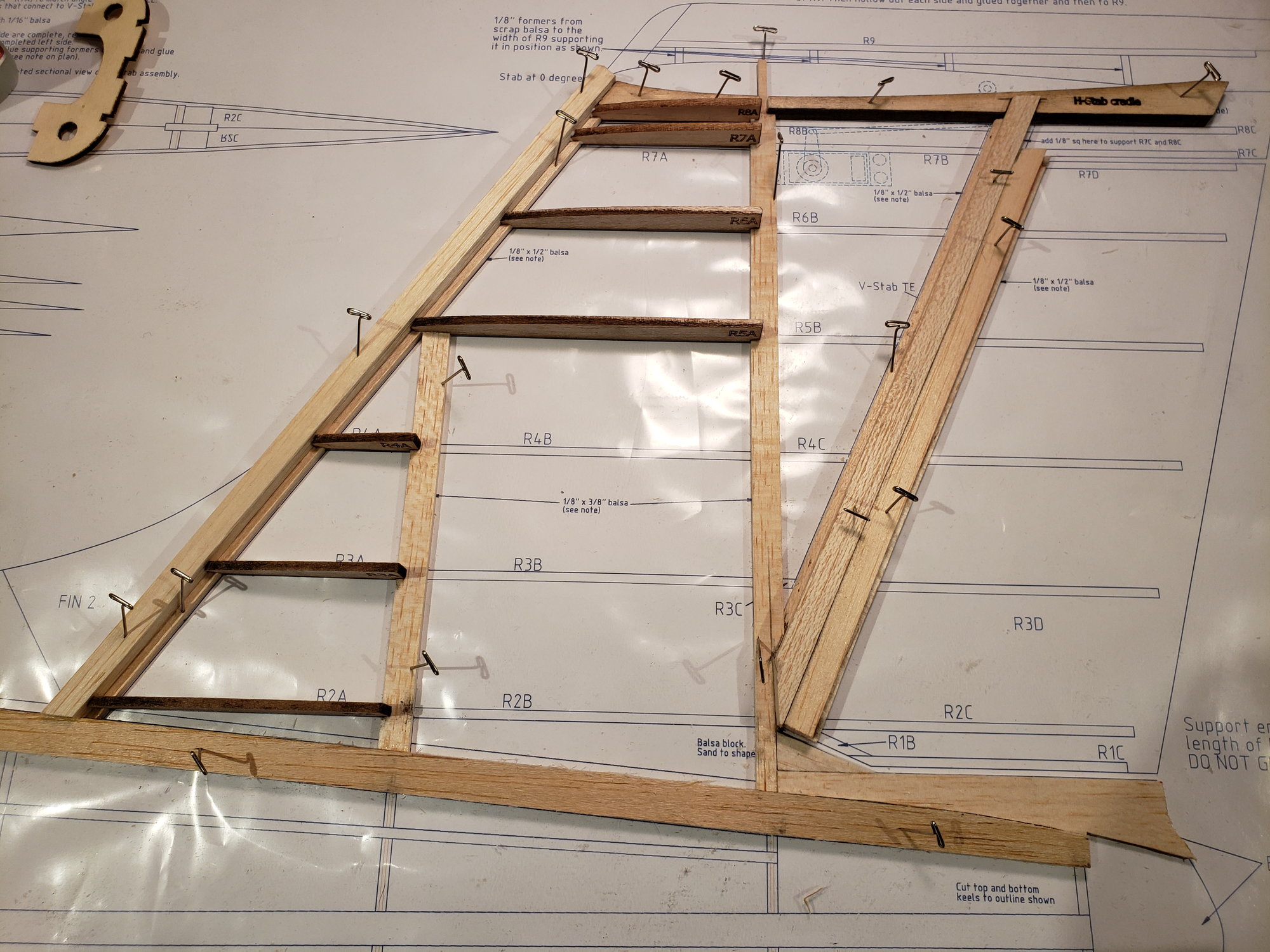
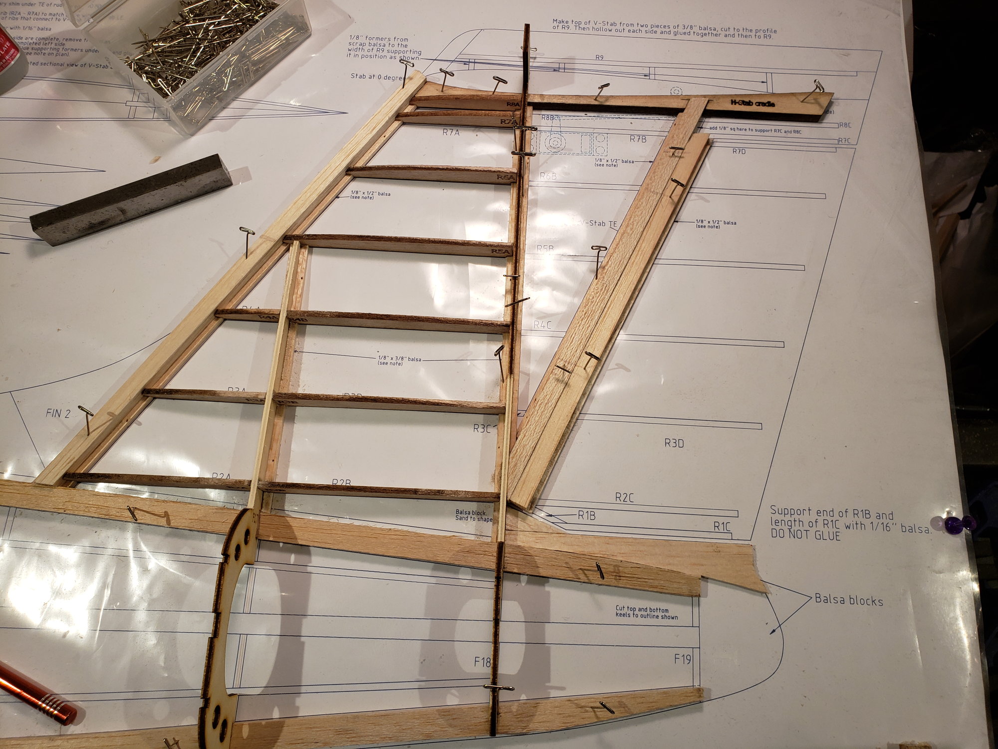
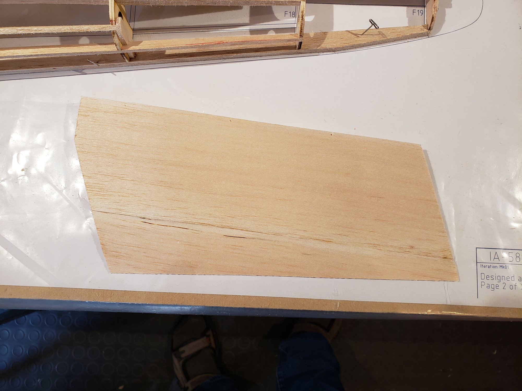
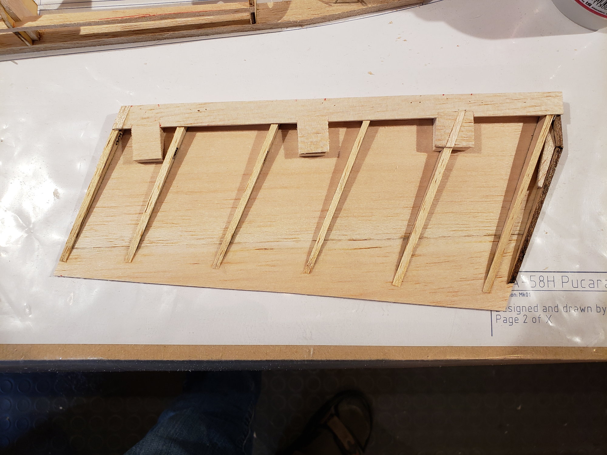
Starting with the H-stab/elevators. The airfoil is fairly thin, using the NACA 0009. So the spar is rather beefy. It is built in 2 halves, top and bottom. The top is built on the plan and the bottom is assembled onto the top, once it's removed from the plan.
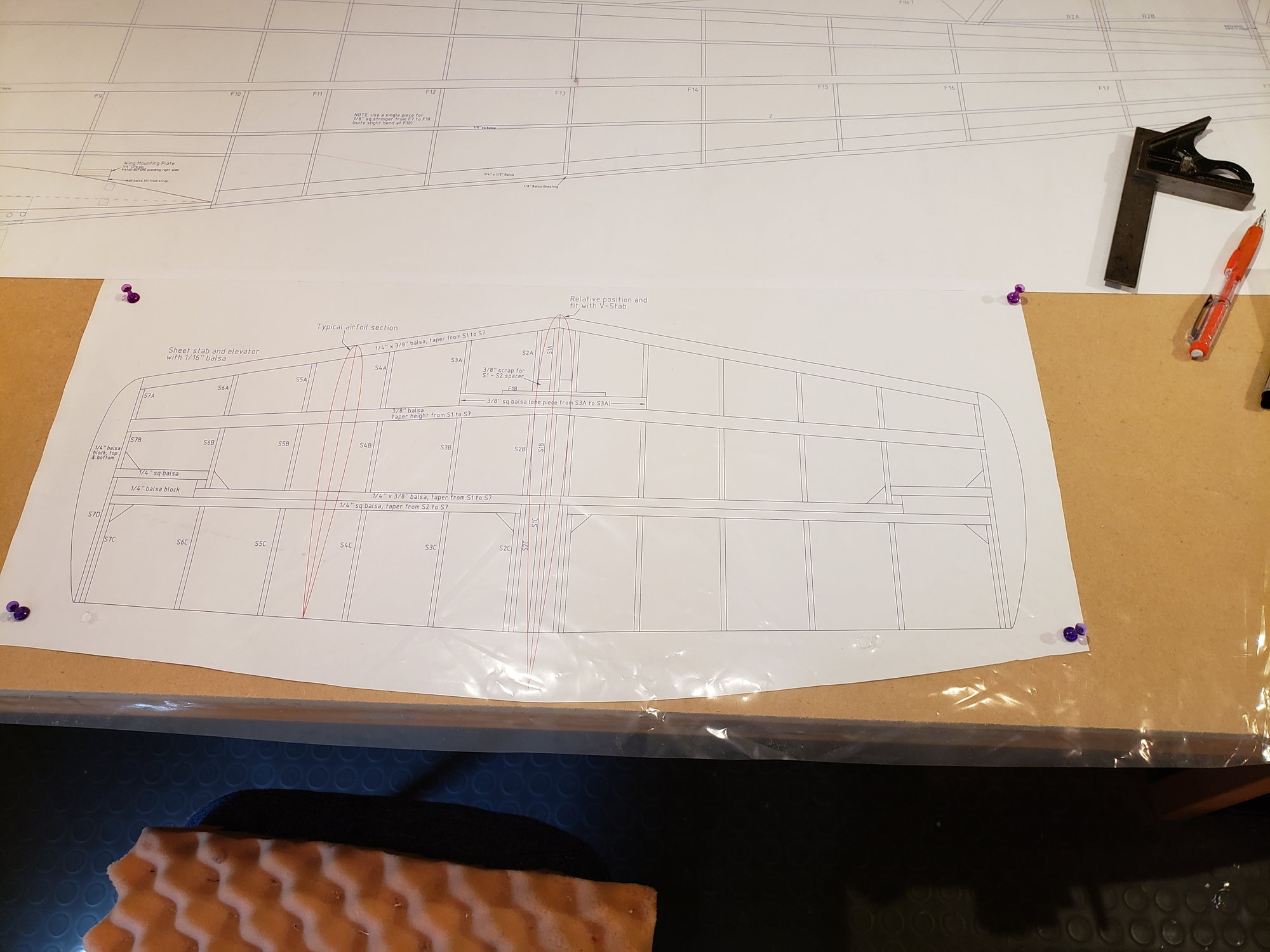
Plan
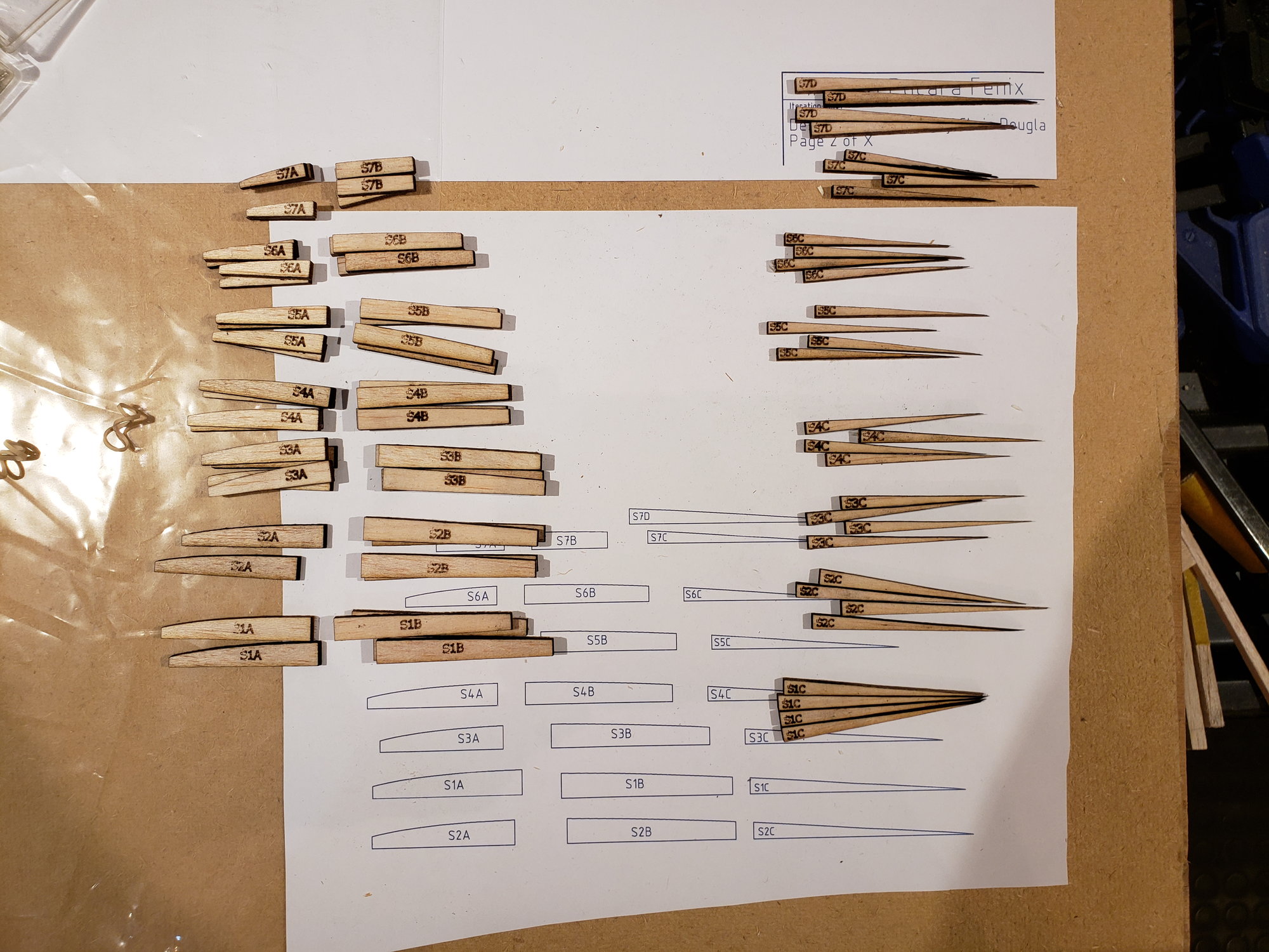
Cut parts
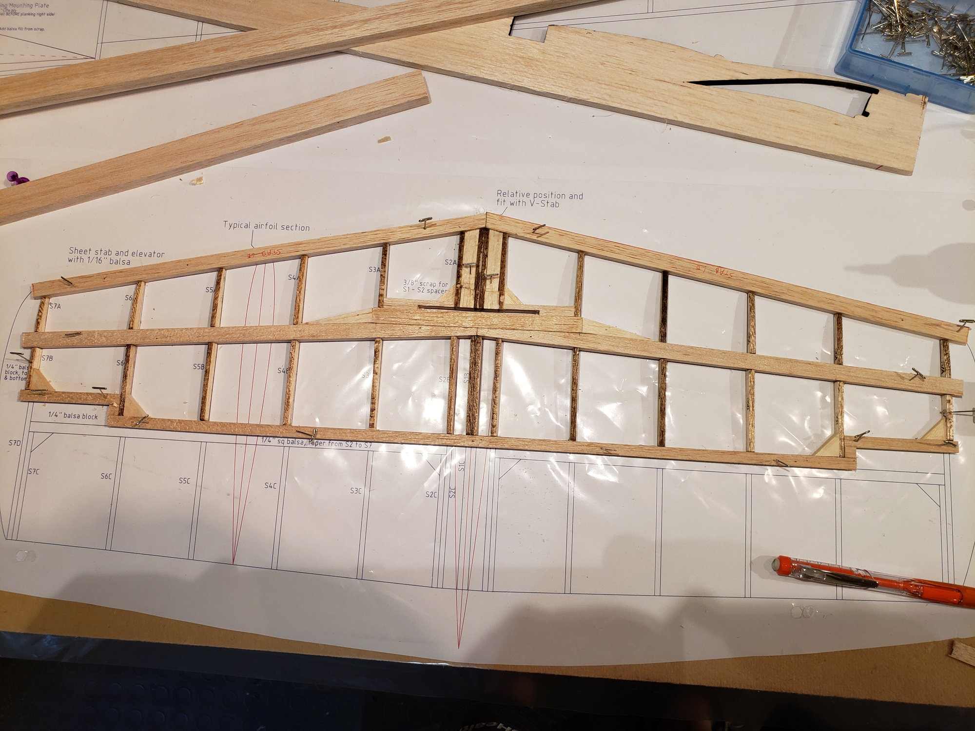
Framing up the top.
Plan
Cut parts
Framing up the top.
09-03-2023, 03:47 PM
#5
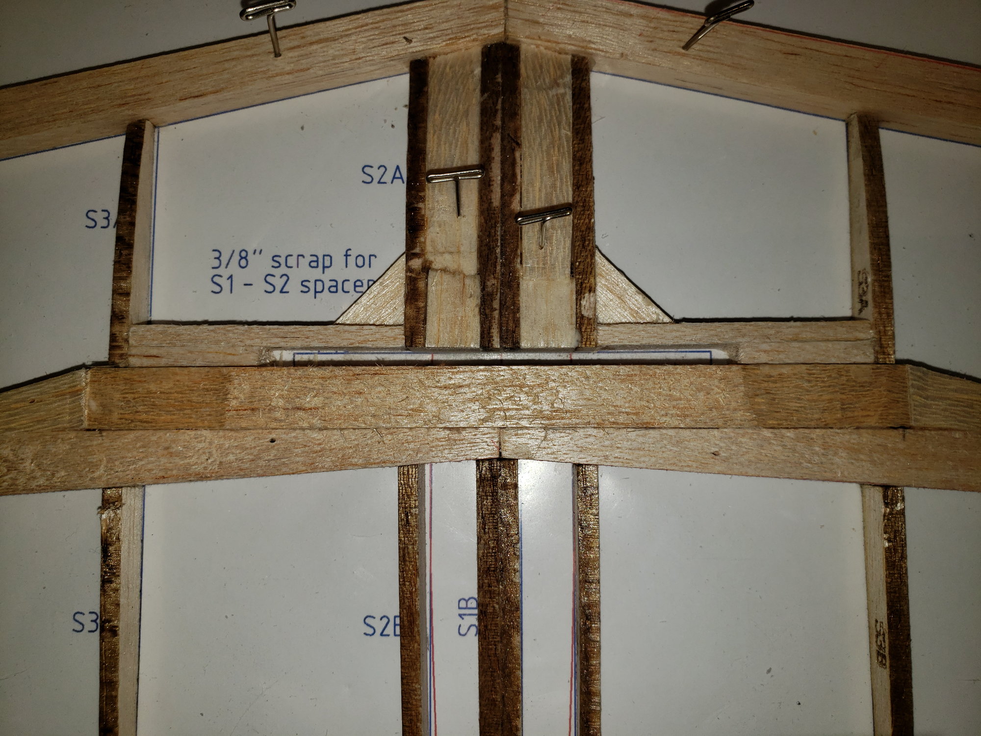
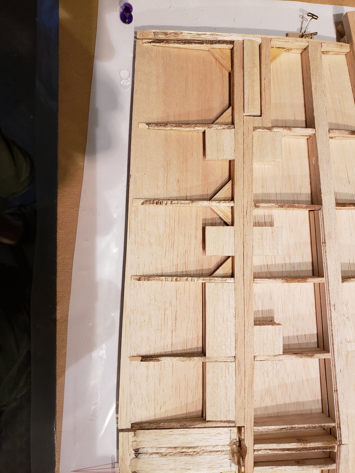
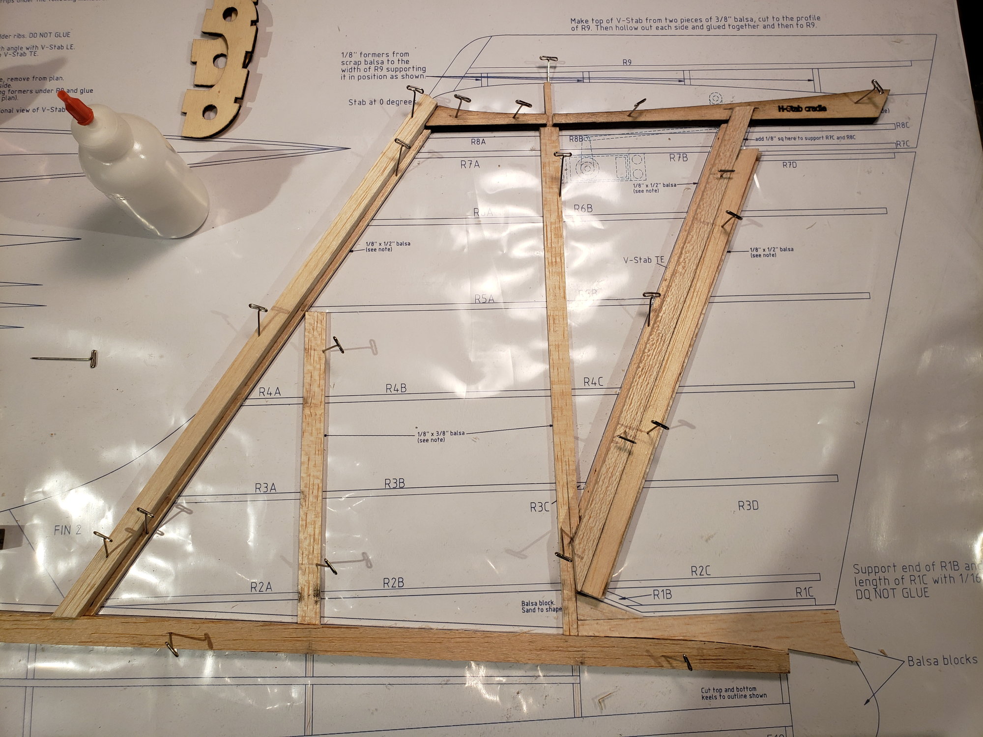
You'll note in the center of the stab's spar is a slot (closeup below). This is for securing the H-stab to the V-stab. Given the T-tail design, the V-stab needs some extra structure. I leveraged an approach from other designers where a couple of fuse formers extend into the V-stab and are made of lite ply. The rear of these will extend all the way into the H-stab insuring both proper alignment and load carrying back down to the fuse.
 09-03-2023, 03:55 PM
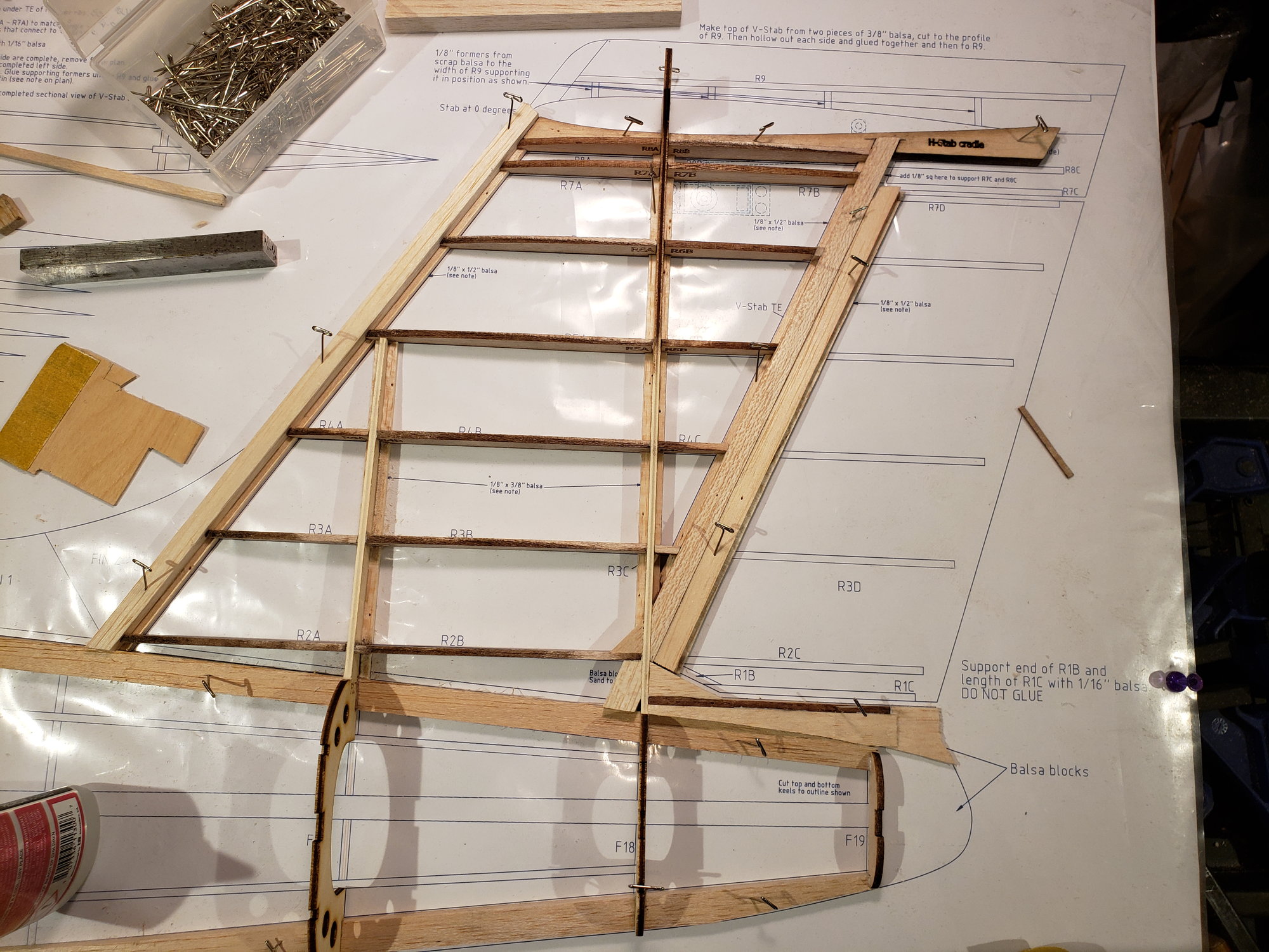
#7
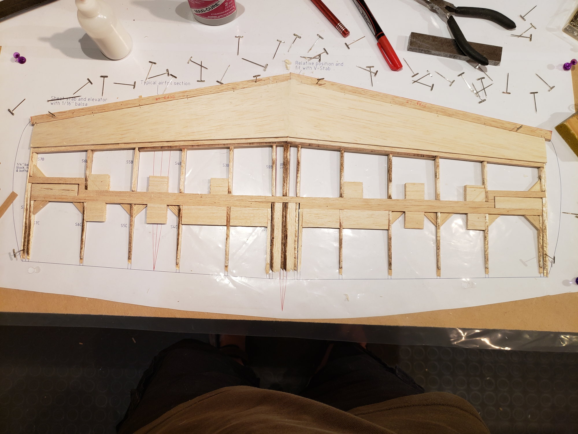
With sheeting of top complete, removed it from the plan and jigged it upside down. Added all rib parts to complete the lower half. The elevator is built the same way.
The following users liked this post:
jescardin (09-15-2023)
09-03-2023, 04:13 PM
#9
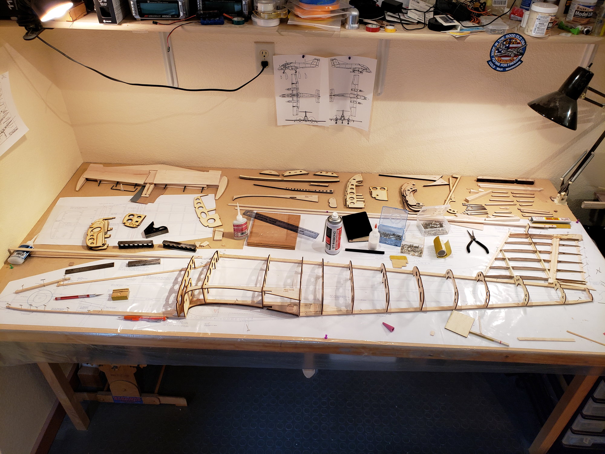
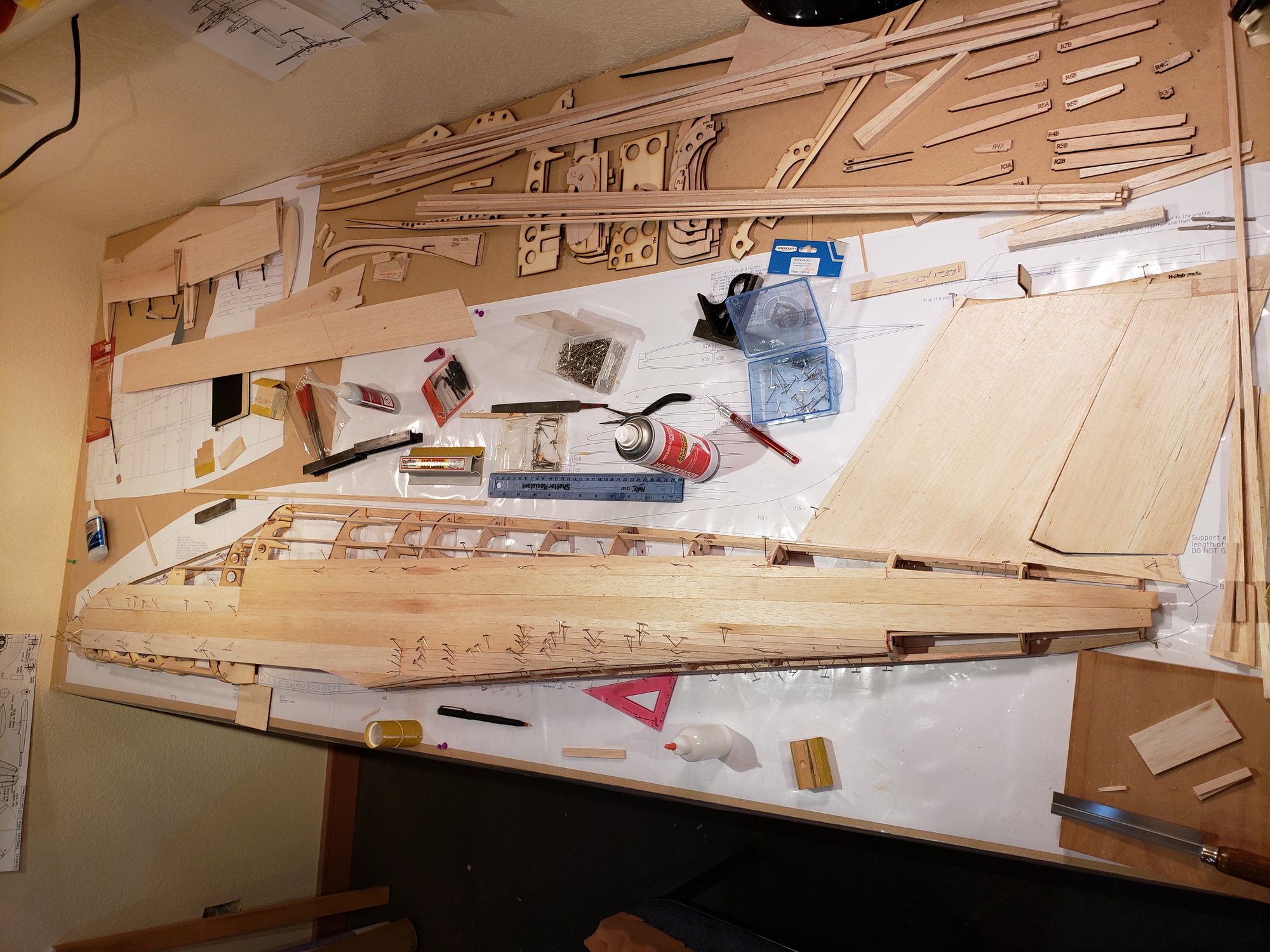
This update brings this thread up to date with the build work I've done to date.
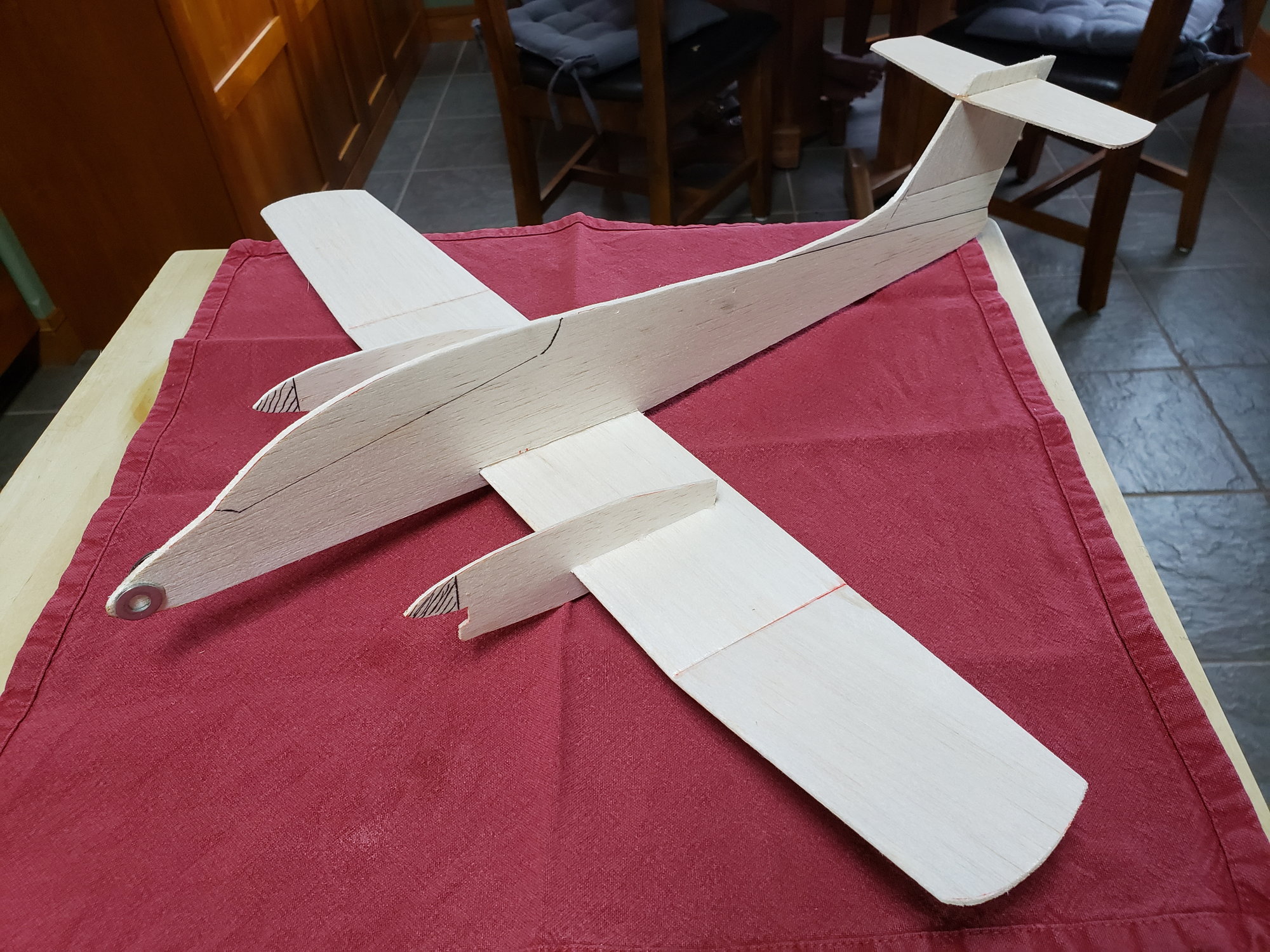
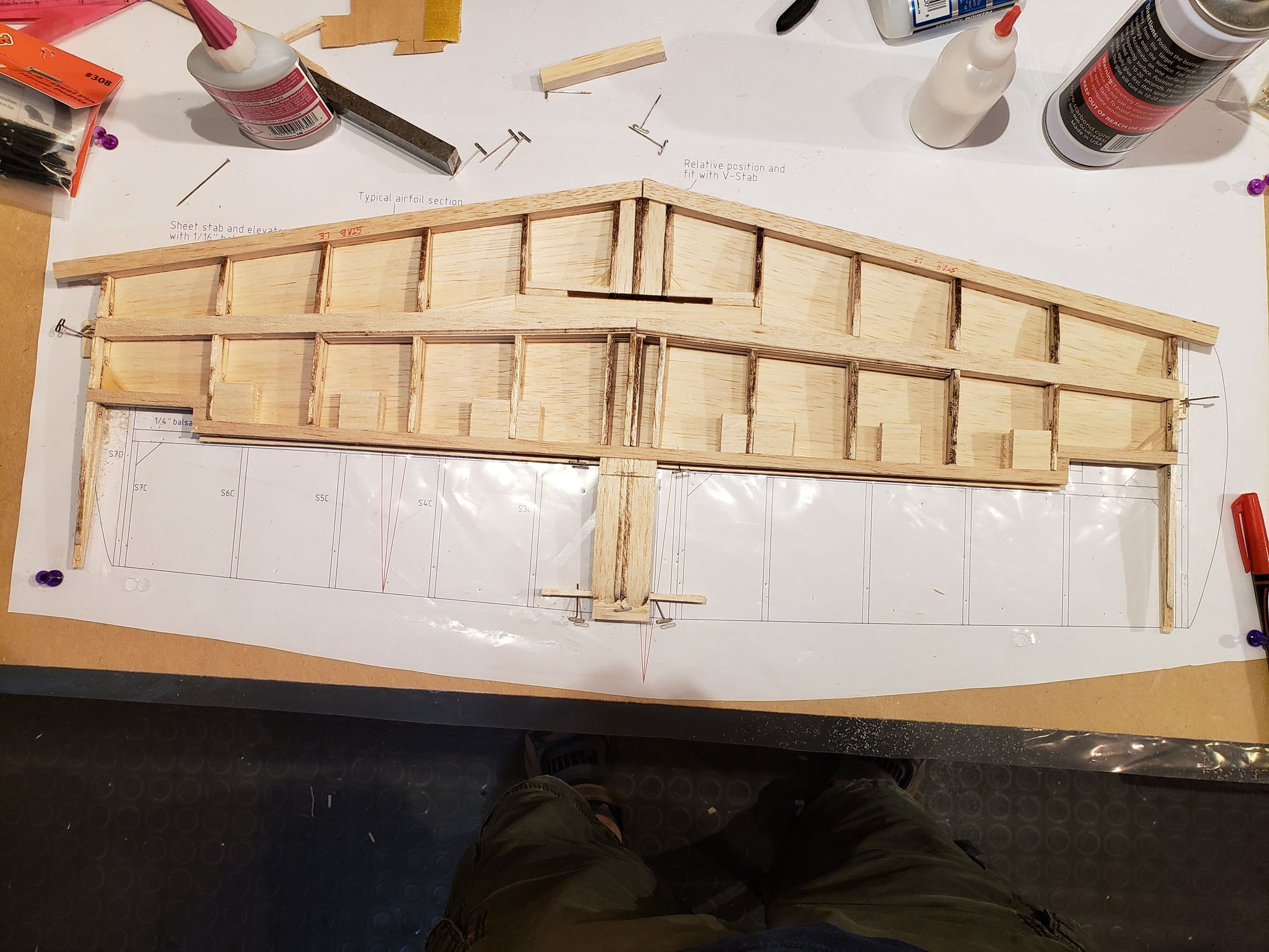
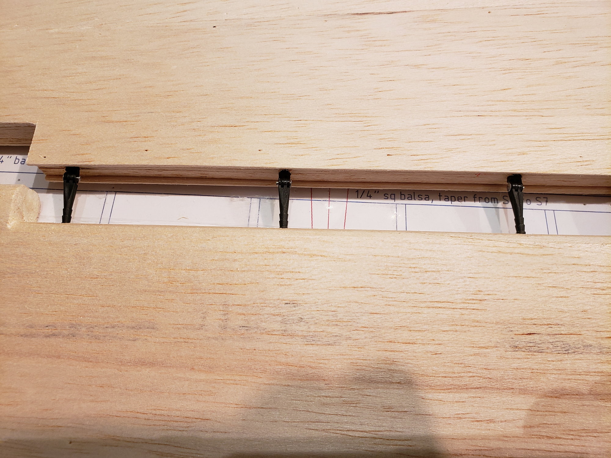
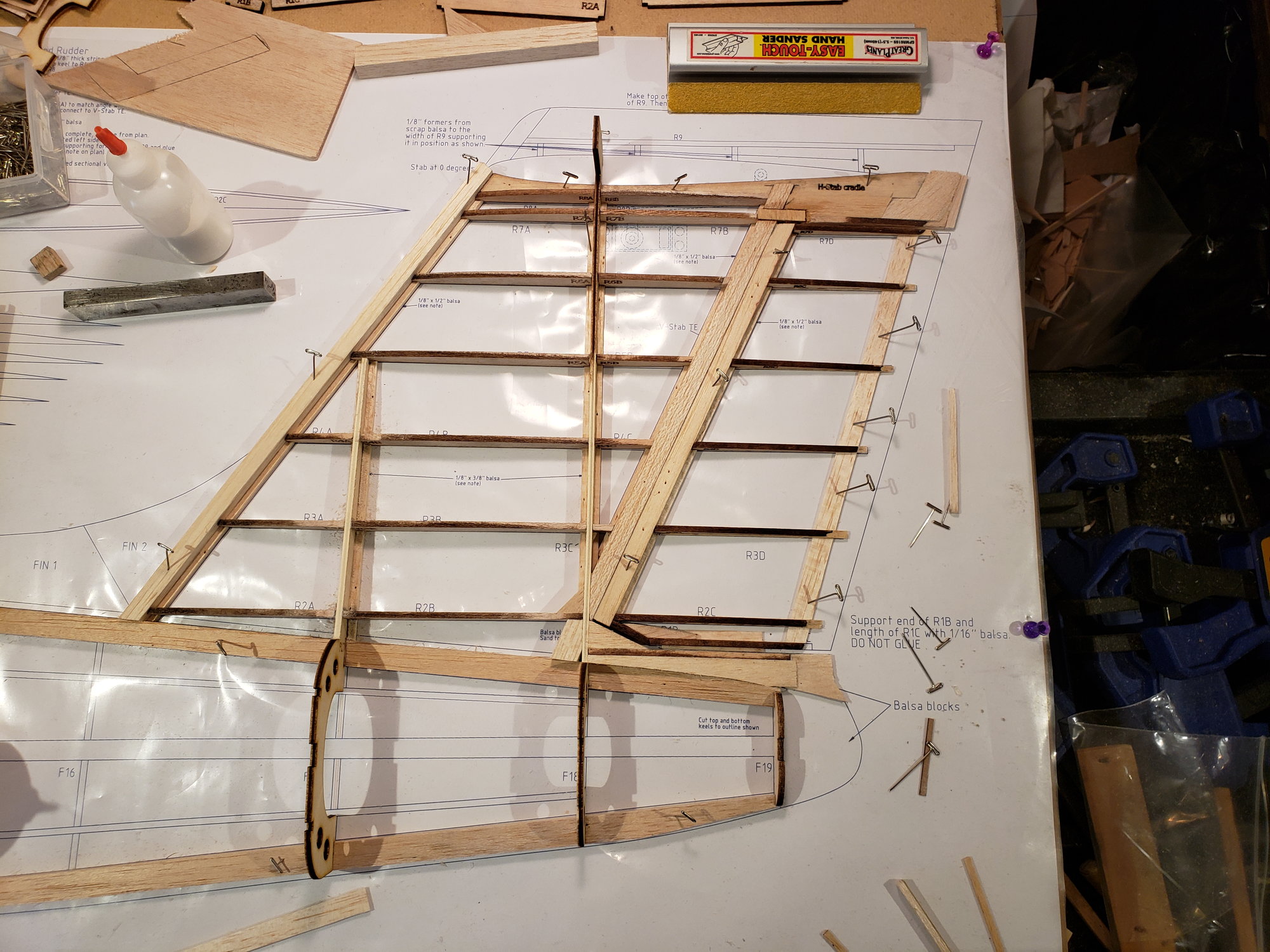
Finished sheeting the bottom. Added tips. Sanded all to shape. Using Robart pin hinges. H-stab is complete for now, moving onto the fuse & V-stab.
Elevator
Pin hinges
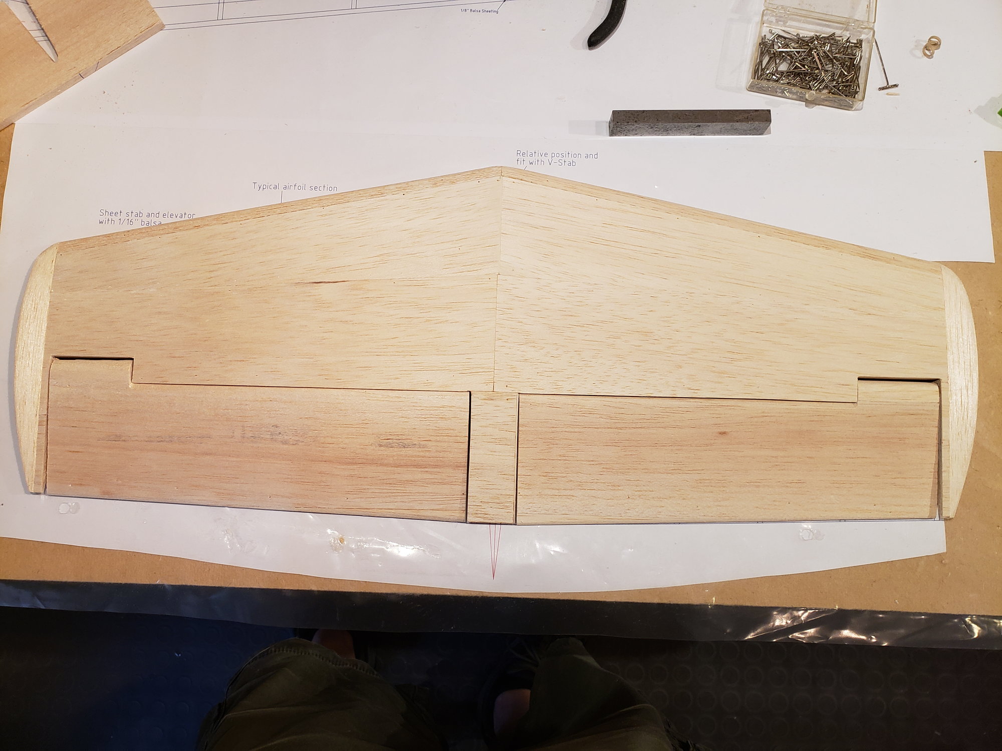
Completed
Finished sheeting the bottom. Added tips. Sanded all to shape. Using Robart pin hinges. H-stab is complete for now, moving onto the fuse & V-stab.
Elevator
Pin hinges
Completed
The following users liked this post:
jescardin (09-15-2023)
09-03-2023, 07:51 PM
#10

Looks great Chris!
I am building a 1/3rd Fokker D6 right now as well, from my own plans. Isn't Autocad wonderful? At this point I have my wings almost done.
My motivation here is to have entry for the designer scale class for the AMA Nationals. Your design may be a good candidate for this class. There are generally few entries.
I will be lurking in the shadows watching your thread.
Rich
Fokker DVI
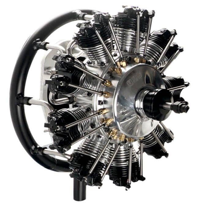
UMS 115cc 9 cylinder
I am building a 1/3rd Fokker D6 right now as well, from my own plans. Isn't Autocad wonderful? At this point I have my wings almost done.
My motivation here is to have entry for the designer scale class for the AMA Nationals. Your design may be a good candidate for this class. There are generally few entries.
I will be lurking in the shadows watching your thread.
Rich
Fokker DVI
UMS 115cc 9 cylinder
09-08-2023, 03:48 PM
#12
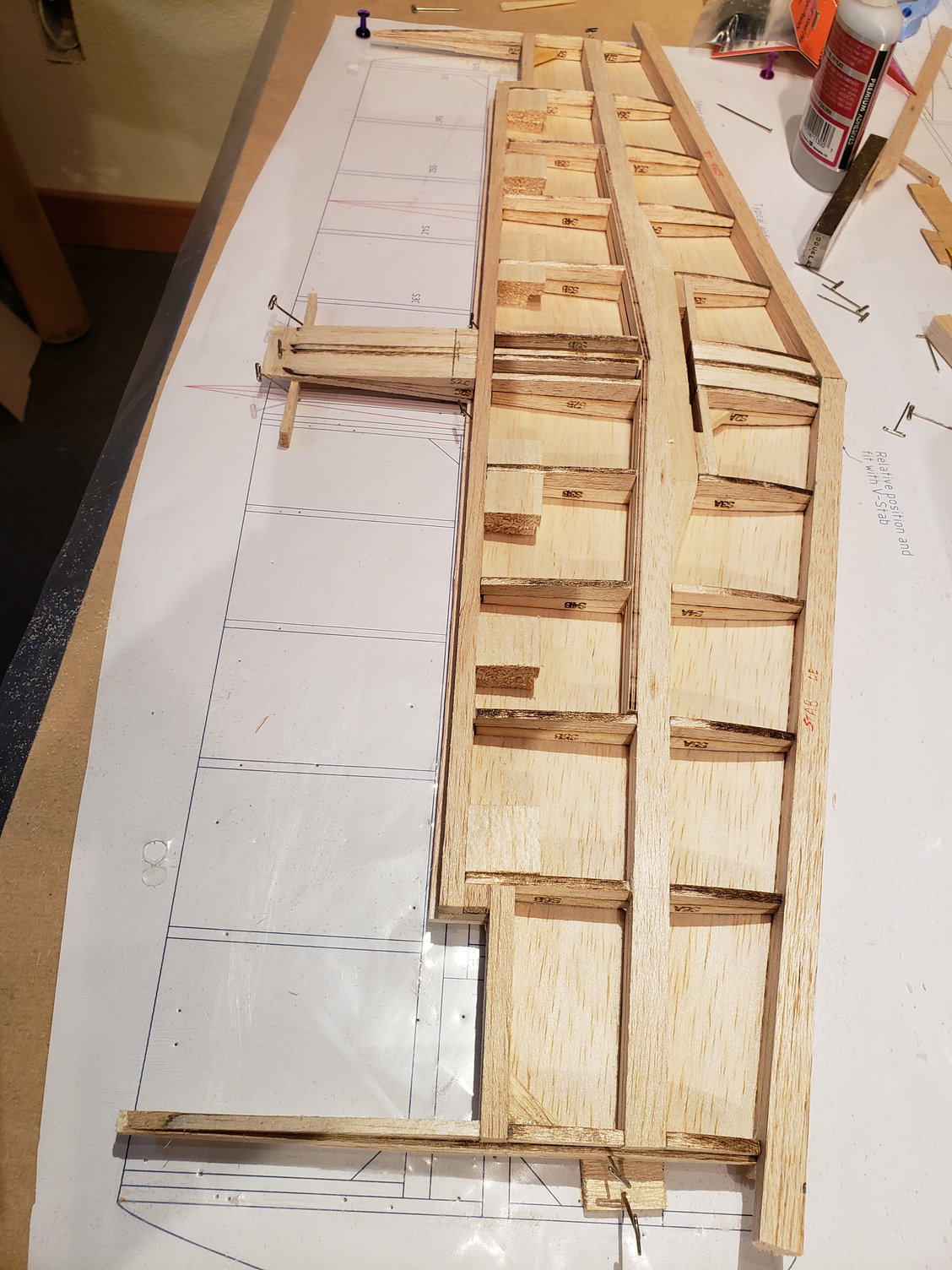
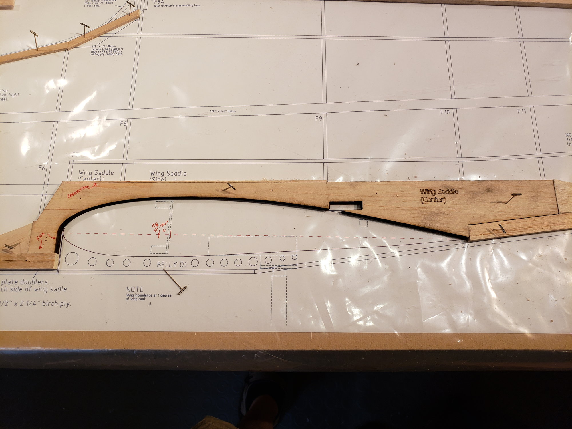
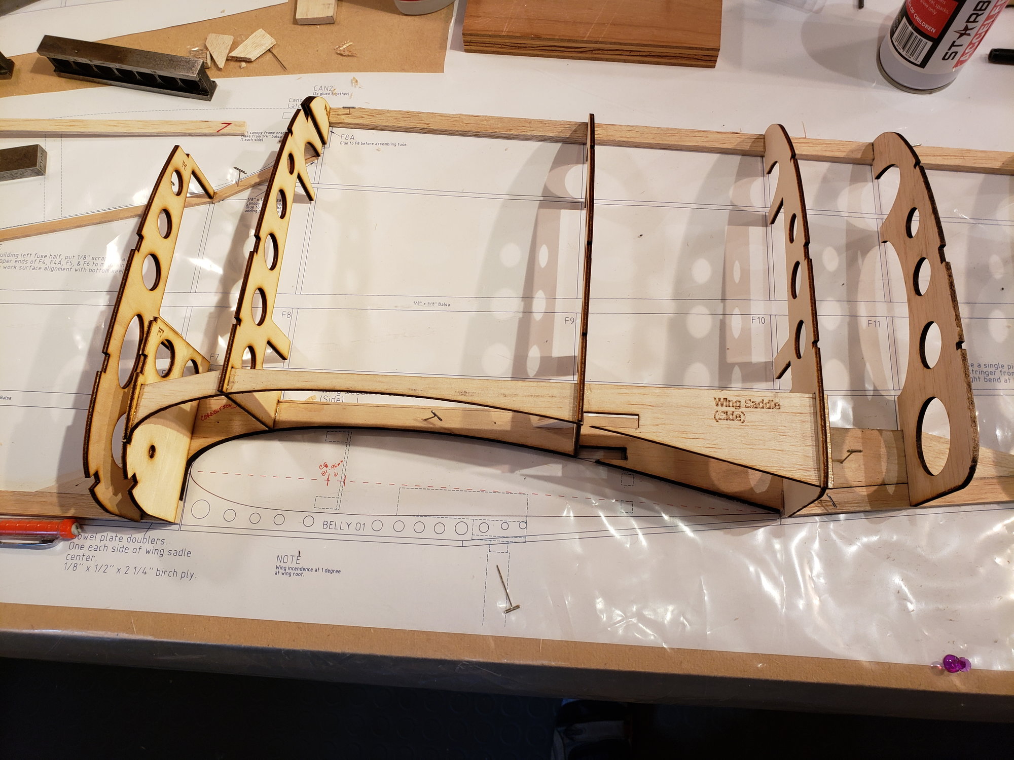
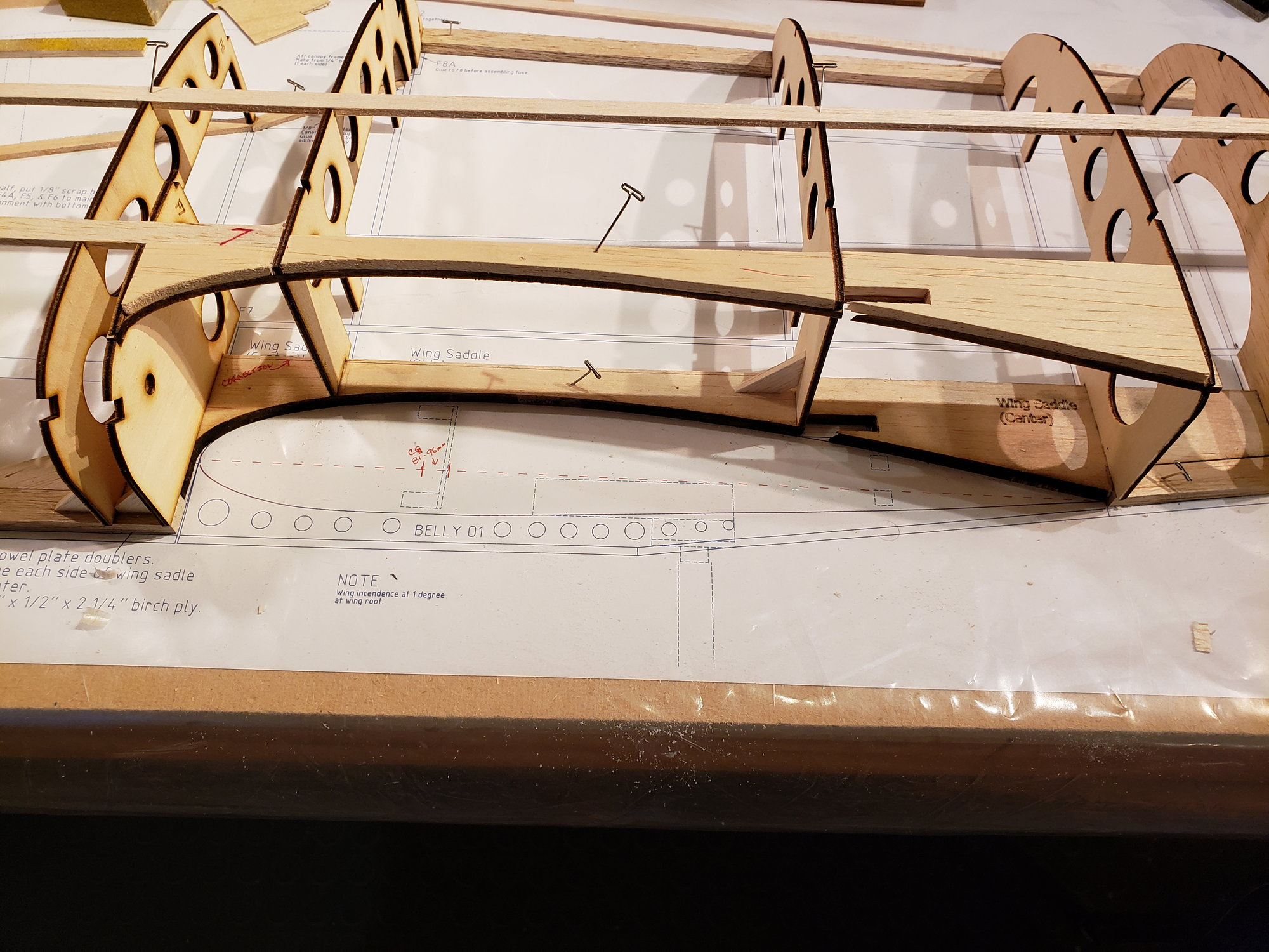
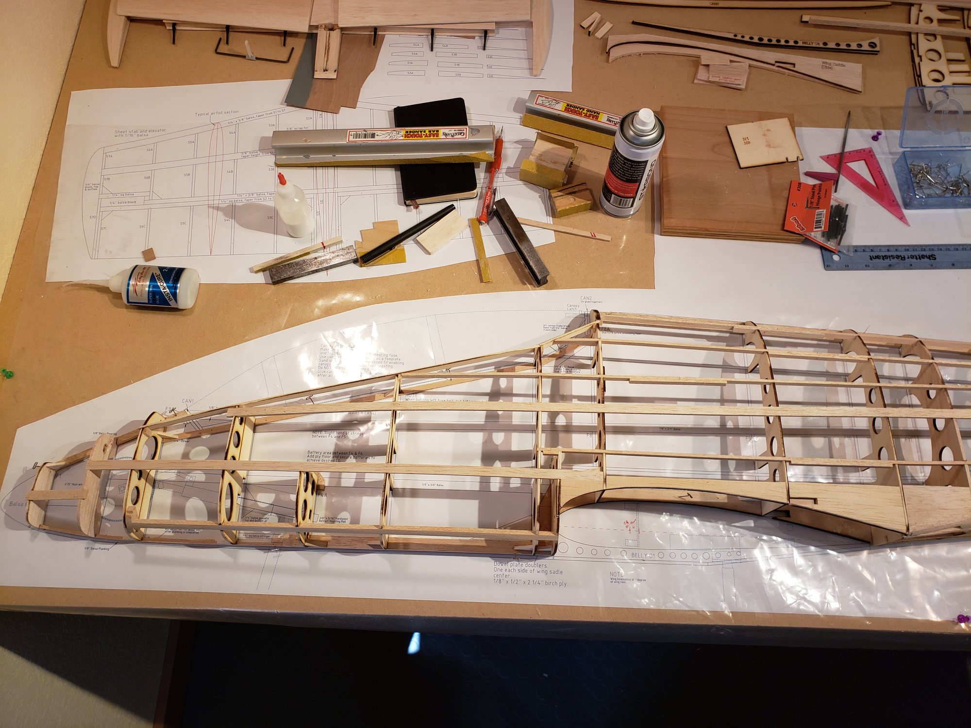
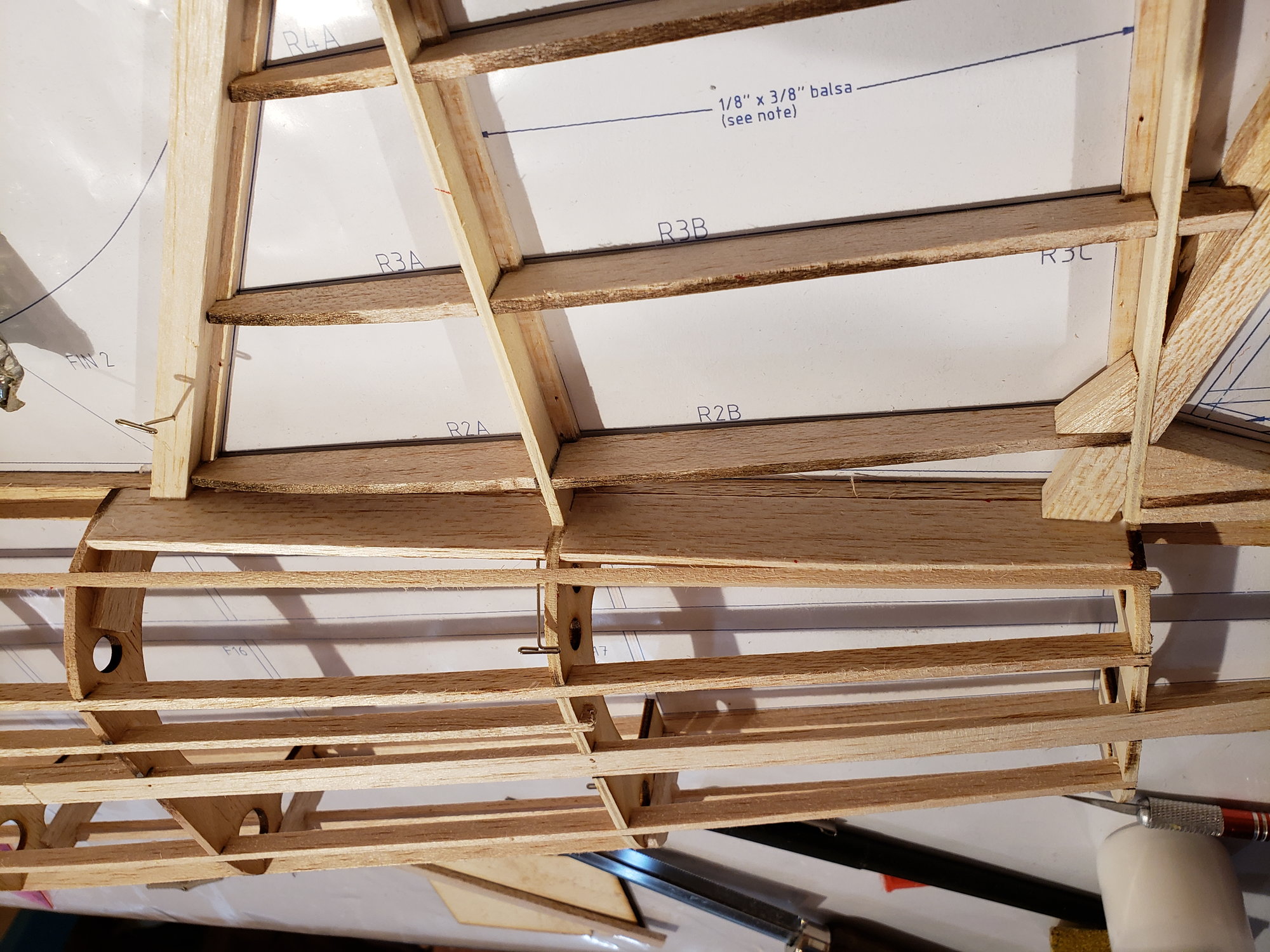
The fuse and V-stab will be built as a single unit using clamshell style construction. The fuse is semi-monocoque design. The longerons are all of hard balsa. Given the center section of the wing is flat (no dihedral) there will be 3 wing saddle pieces. The central one (shown here) is 1/4" think and will help carry loads across the wing opening.
V-stab and rudder leading edge are soft balsa. Other balsa is hard.
V-stab and rudder leading edge are soft balsa. Other balsa is hard.
The following users liked this post:
jescardin (09-27-2023)
09-12-2023, 12:22 PM
#16
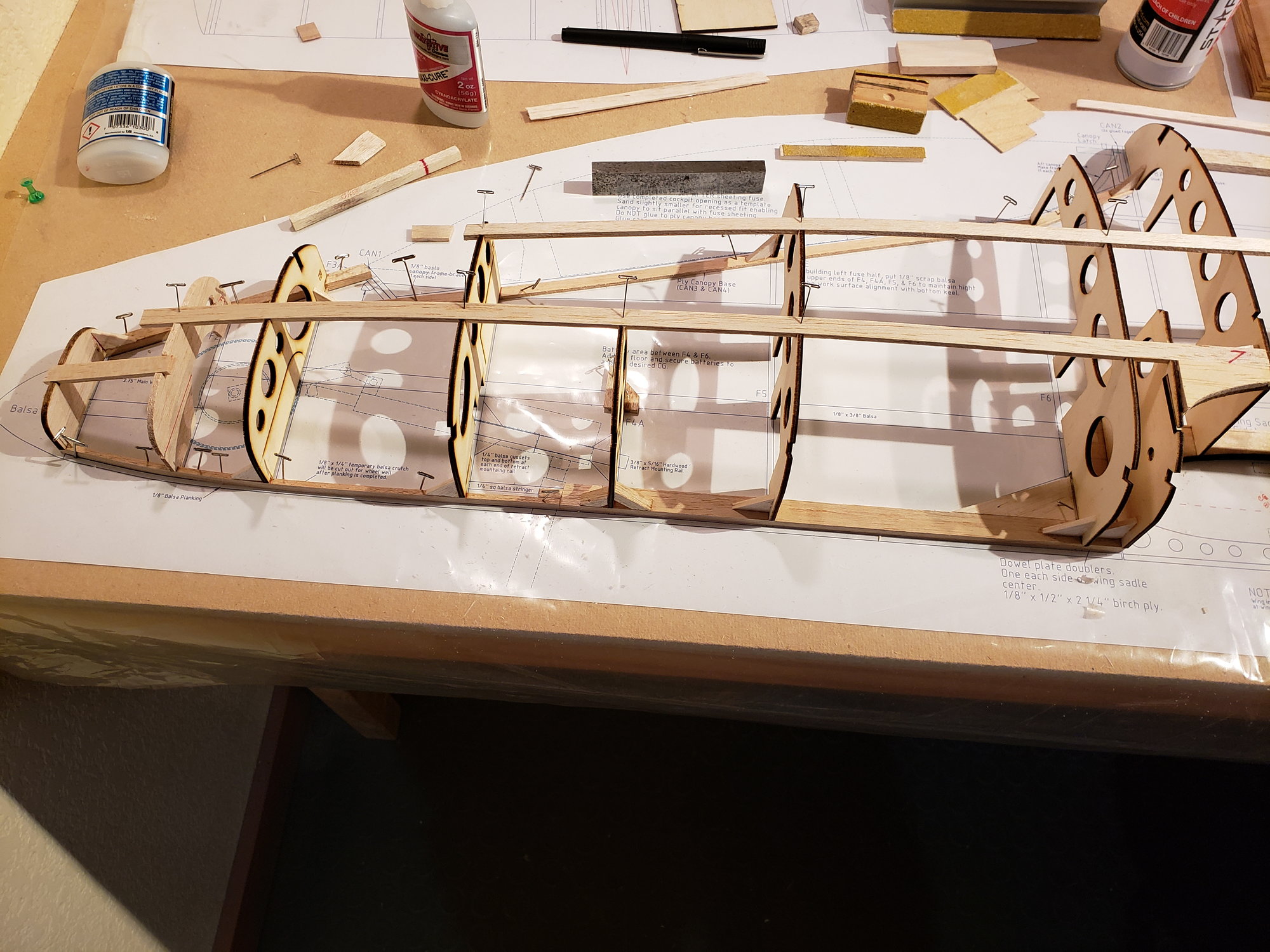
Finished adding the formers to the forward fuse. Doublers were installed on the outer wing saddle to make a smooth transition from the wing to the fuse.
Then installed longerons / stringers.
Then installed longerons / stringers.
09-12-2023, 12:27 PM
#17
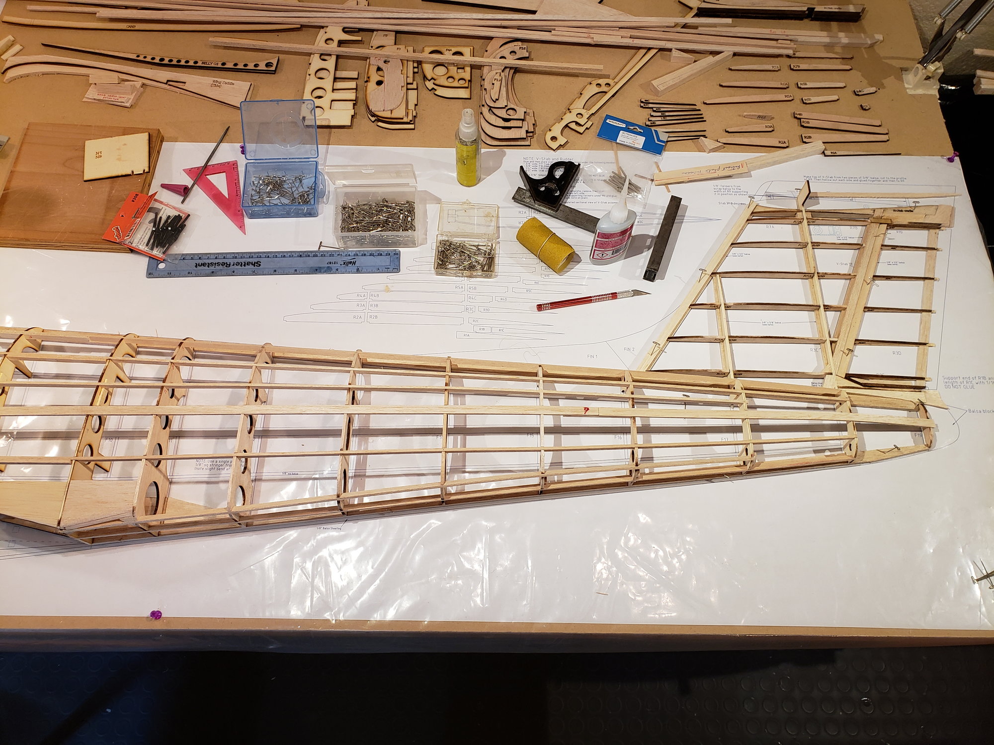
Sheeting of the Vertical stab and rudder was done in the usual manner. 1/16" lite balsa.
Starting the sheeting .
Sheeted Rudder. .
Installed hinge blocks. .
1/8" sheet installed at the base of the V-stab make for a solid transition from stab to fuse. .
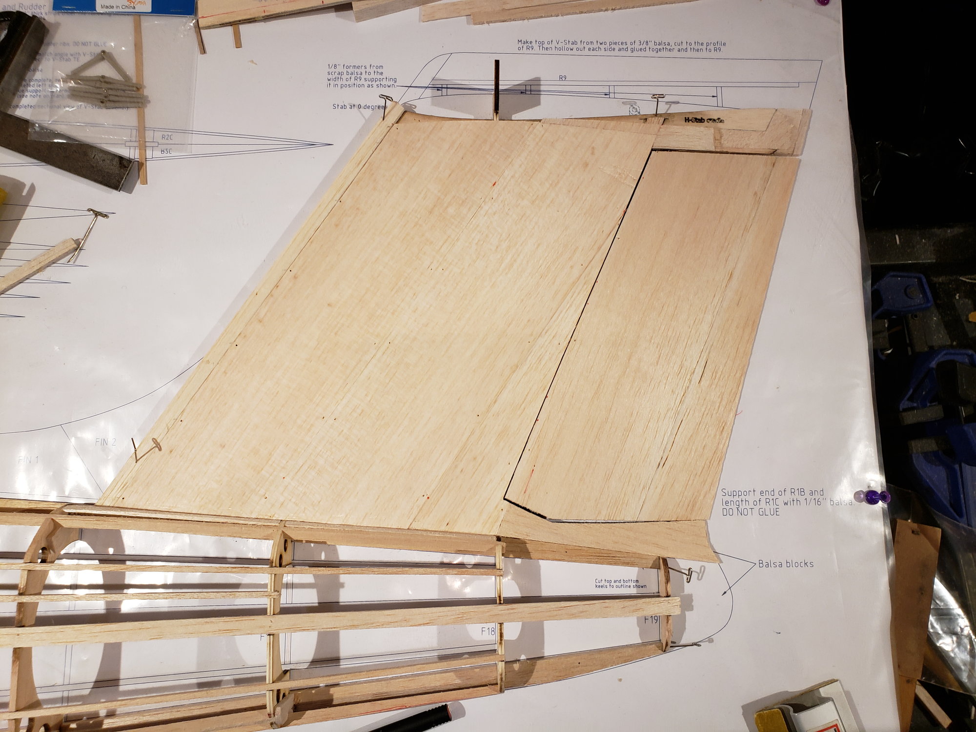
Completed stab and rudder.
Starting the sheeting .
Sheeted Rudder. .
Installed hinge blocks. .
1/8" sheet installed at the base of the V-stab make for a solid transition from stab to fuse. .
Completed stab and rudder.
The following users liked this post:
jescardin (09-15-2023)
09-14-2023, 05:13 PM
#20
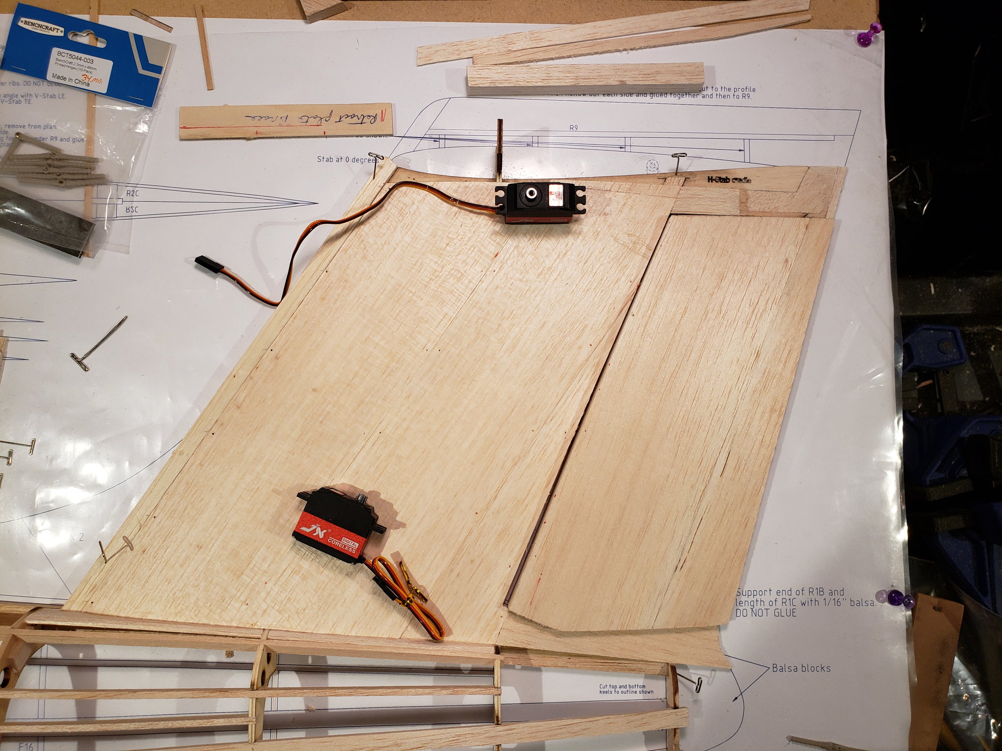
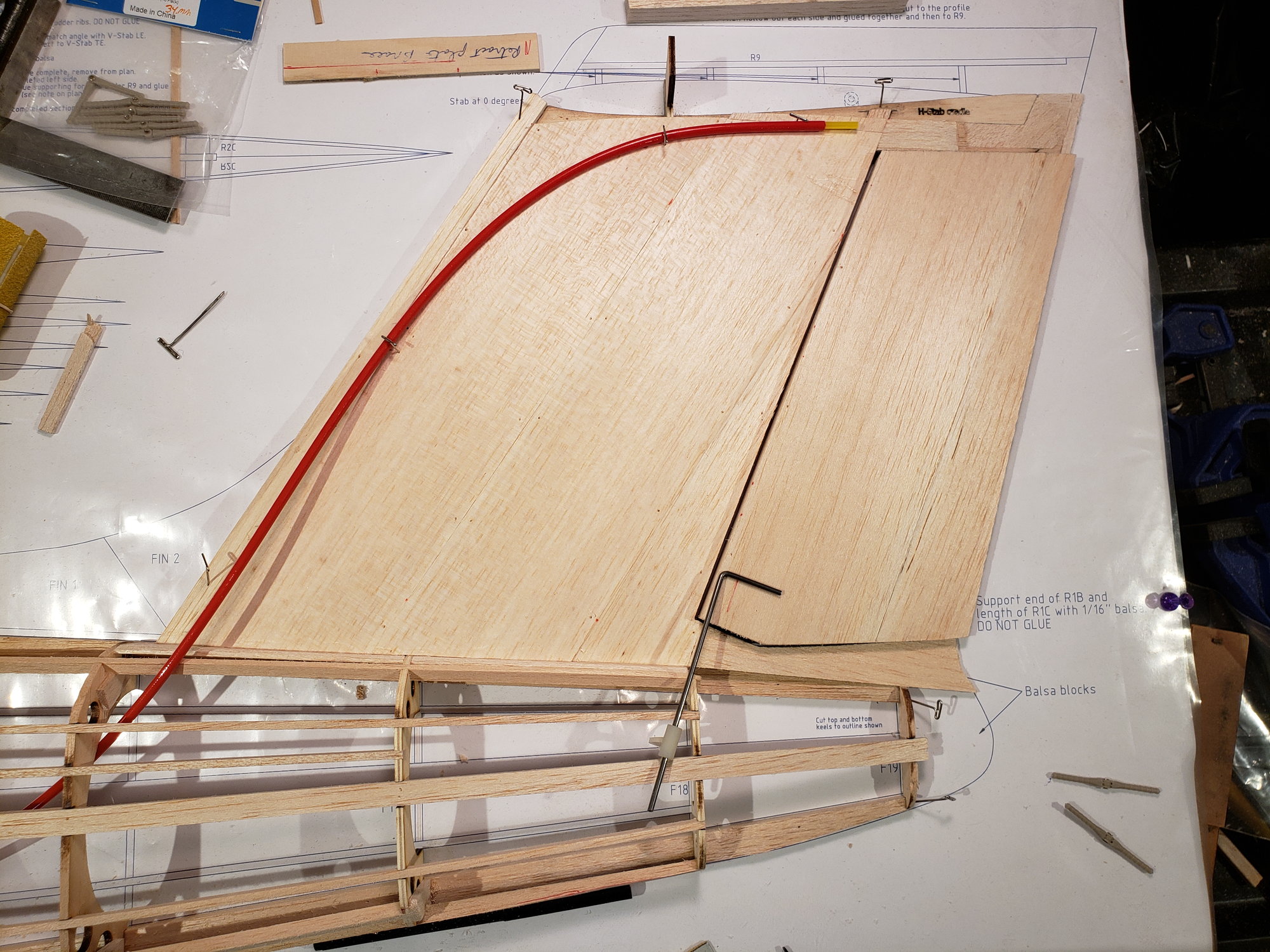
Location of the elev and rudder servos are really "your choice", should you choose to build a Fenix. However, there are 2 options.
1) The V-stab has been set up to accommodate 2 - 3 6kg servos (1 for the rudder and either 1 or 2 for the elev). See the first pict below for where they would go, but they are between pairs of ribs. They are placed against the F18 ply former, which would be a good place to glue servo supports to.
2) Mount them in the fuse with push-rods to the elev/rudd. There is room to snake a flexible pushrod up the V-stab to reach the elev. In this case the elevators are joined by a Dubro elevator horn mounted in the V-stab. Similar, the rudder gets a horn mounted into the fuse and driven directly by a servo. See the second pict for this setup.
I'll be going with #2. It's a bit more work, but results in controls that are completely hidden.
09-14-2023, 05:17 PM
#21
. Saves SO MUCH TIME. In this case though, it's hard to get it wrong. Once the planking of the left side is complete, I will lift the fuse, flip it over, and support it on it's left side. The right side is then built on top of the left.
09-14-2023, 05:21 PM
#22
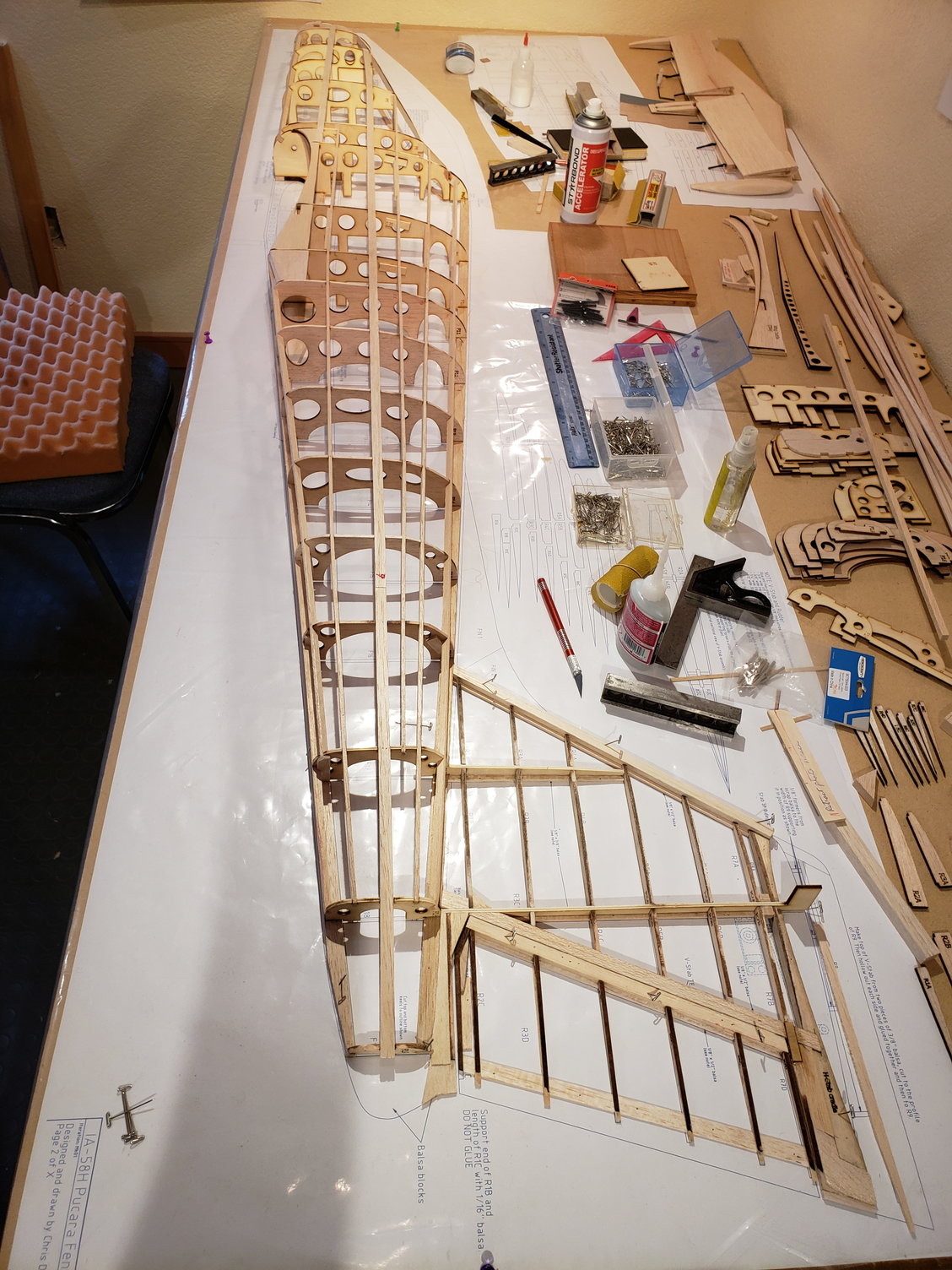
A couple months ago I built an 18" test section of the wing to see how the parts were fitting. I figured at this point, I could see how well the wing is going to mate to the fuse, which turned out GREAT. ... being able to draw all this in CAD really helps improve the quality of the fit of parts.
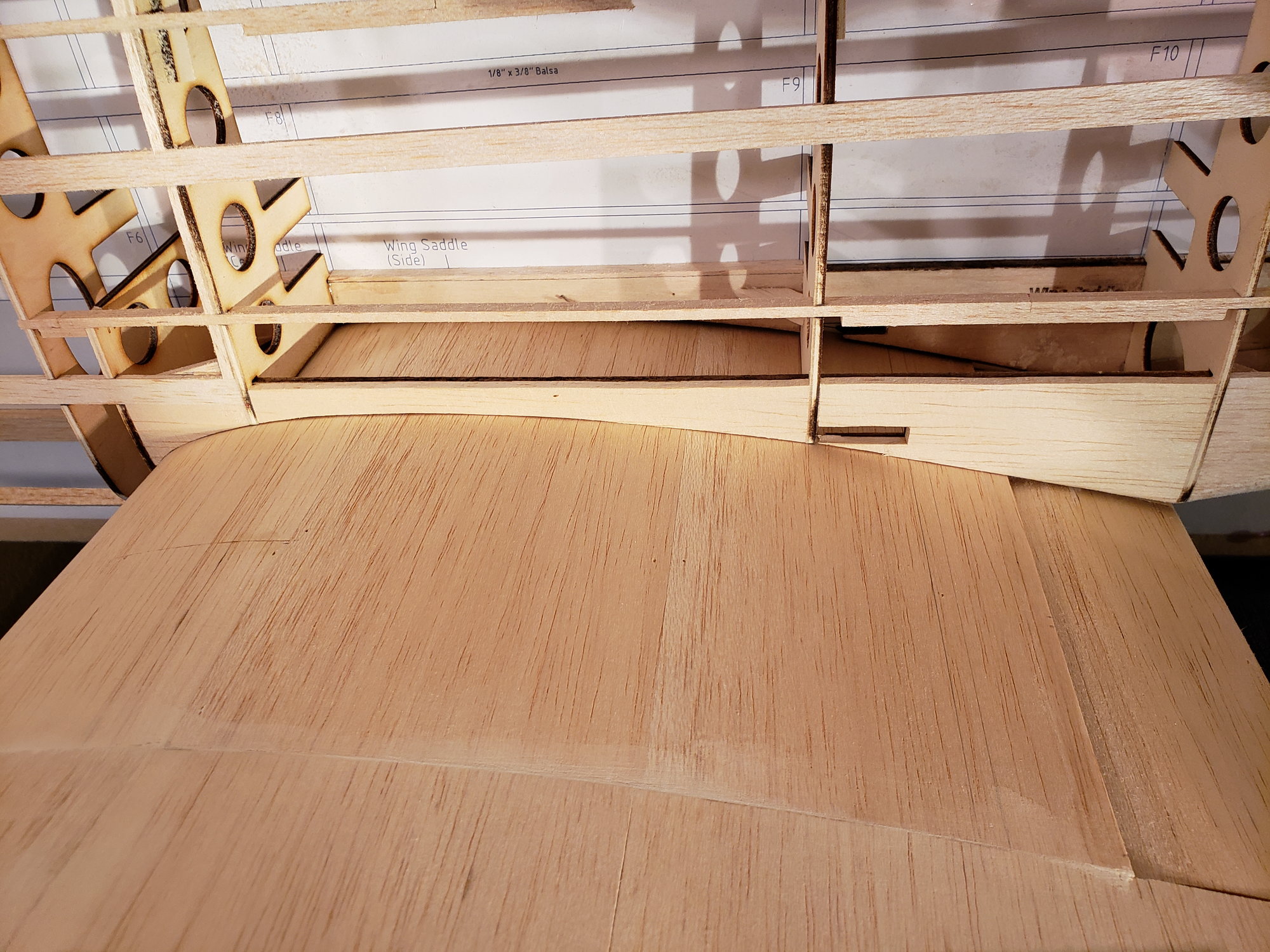
Wing test section fitted to the fuse. PERFECT!
Wing test section fitted to the fuse. PERFECT!
The following users liked this post:
jescardin (09-27-2023)
09-14-2023, 07:18 PM
#24
Chris,
When you were mentioning the servos, you gave the impression someone else may be building this. Are you planning to make these plans available to the public?
I did notice you have what appears to be full text and construction notes on the plans. For my Fokker, I am just going as far as I need with the plans to build my own model. Of course I can always add more details later if need be. That type of detail contributes greatly to the time added to the CAD work.
09-15-2023, 06:09 AM
#25
...
I did notice you have what appears to be full text and construction notes on the plans. For my Fokker, I am just going as far as I need with the plans to build my own model. Of course I can always add more details later if need be. That type of detail contributes greatly to the time added to the CAD work.
I did notice you have what appears to be full text and construction notes on the plans. For my Fokker, I am just going as far as I need with the plans to build my own model. Of course I can always add more details later if need be. That type of detail contributes greatly to the time added to the CAD work.
 ... truly a massive effort to put in all the build notes. Not to mention the need to make the plans complete. Clearly, when only working for yourself, you need only provide enough lines on the page to guide the mental picture you have to completion.
 To your first question ... will I be making the plan available? Yes. Once the plane is a proven flyer, I plan to make short kits with plans, cut parts and canopies available. I expect to release the plans into the public domain through Outerzone or similar plan site. The current plane I'm building here in this thread is a prototype. The production version will have removeable wing panels and other improvements that evolve over the coming months. The broader goal here is around a small business I'm starting. The focus of the business is to provide short kits and plans for unusual but interesting or noteworthy aircraft. They will be as scale as I can reasonably make them without giving up good handling. I have a growing list of planes that the fit this bill. Most have not been kitted before or only in a very limited way.