


Scratchbuild a Curtiss Hawk III (BF2C-1) in 1/4.5
 09-30-2019, 07:53 AM
#76

Hi Thomas, I posted a link over in the Saito Club thread and they were very impressed by your exhaust system! These guys are constantly rebuilding Saitos and comparing performance and several are master machinists and you impressed them. I thought you might want to know.
Mike
Mike
 11-02-2019, 12:42 PM
#77

Thread Starter

Join Date: Jan 2014
Location: Eppendorf, Saxonia, Germany
Posts: 129
Likes: 0
Received 7 Likes
on
7 Posts
thank you Mike for your recommendation, it`s a real compliment.
After finishing the engine things, it`s time to start with the RC-equipment.
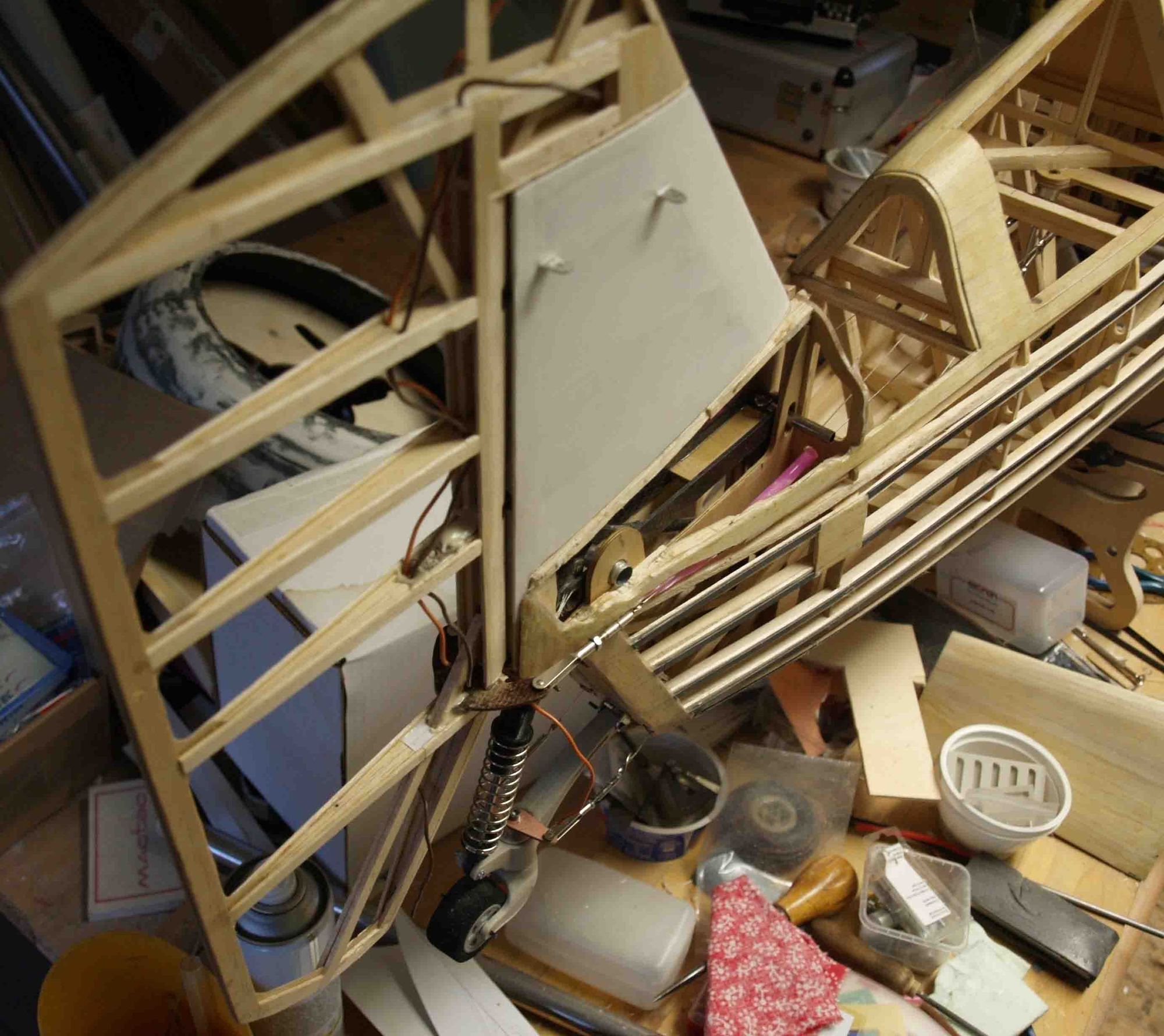
At first I`ve done the tail, starting with the tail wheel.
A friend of mine, owning a 3-d-printer made me the parts. I`ve done the metal work.
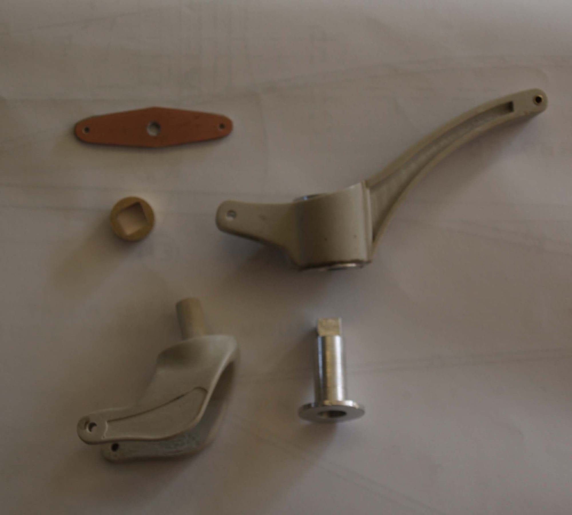
completed it looks so
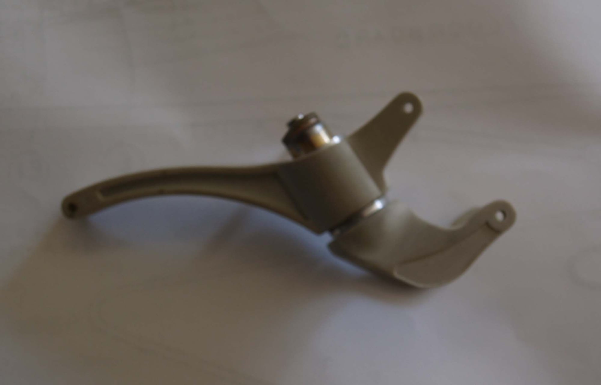
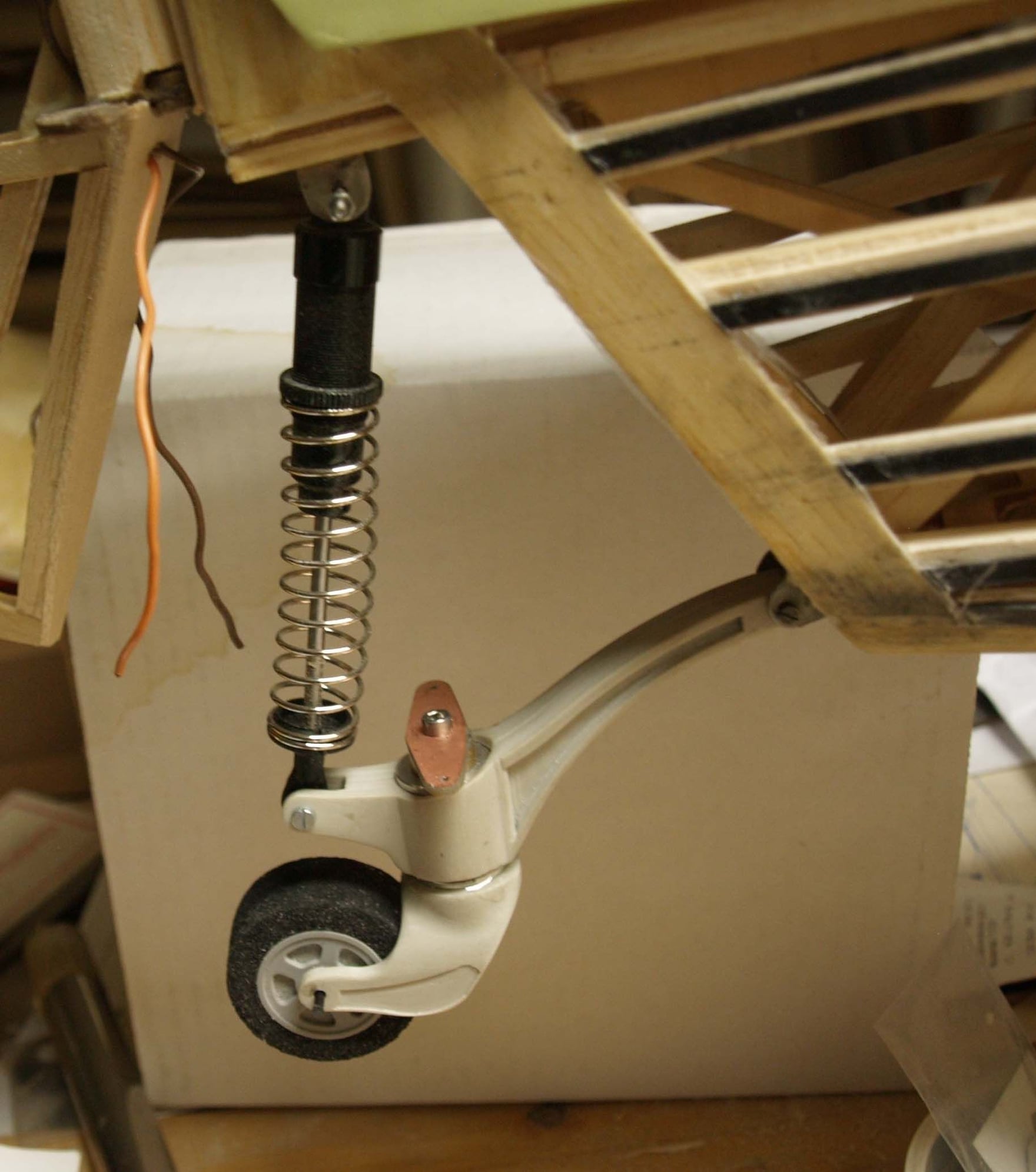
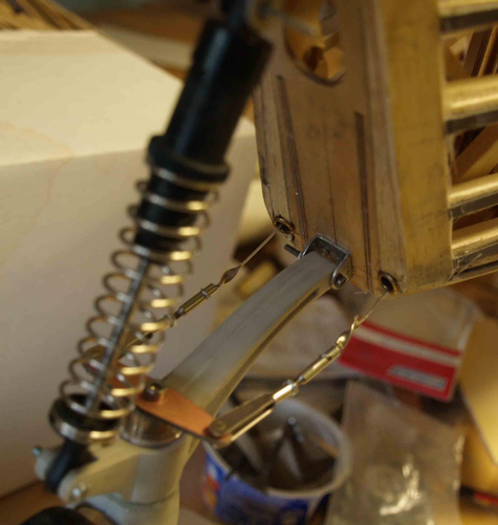
now it`s added to the hull. I use a shockadsorber from an RC-car.
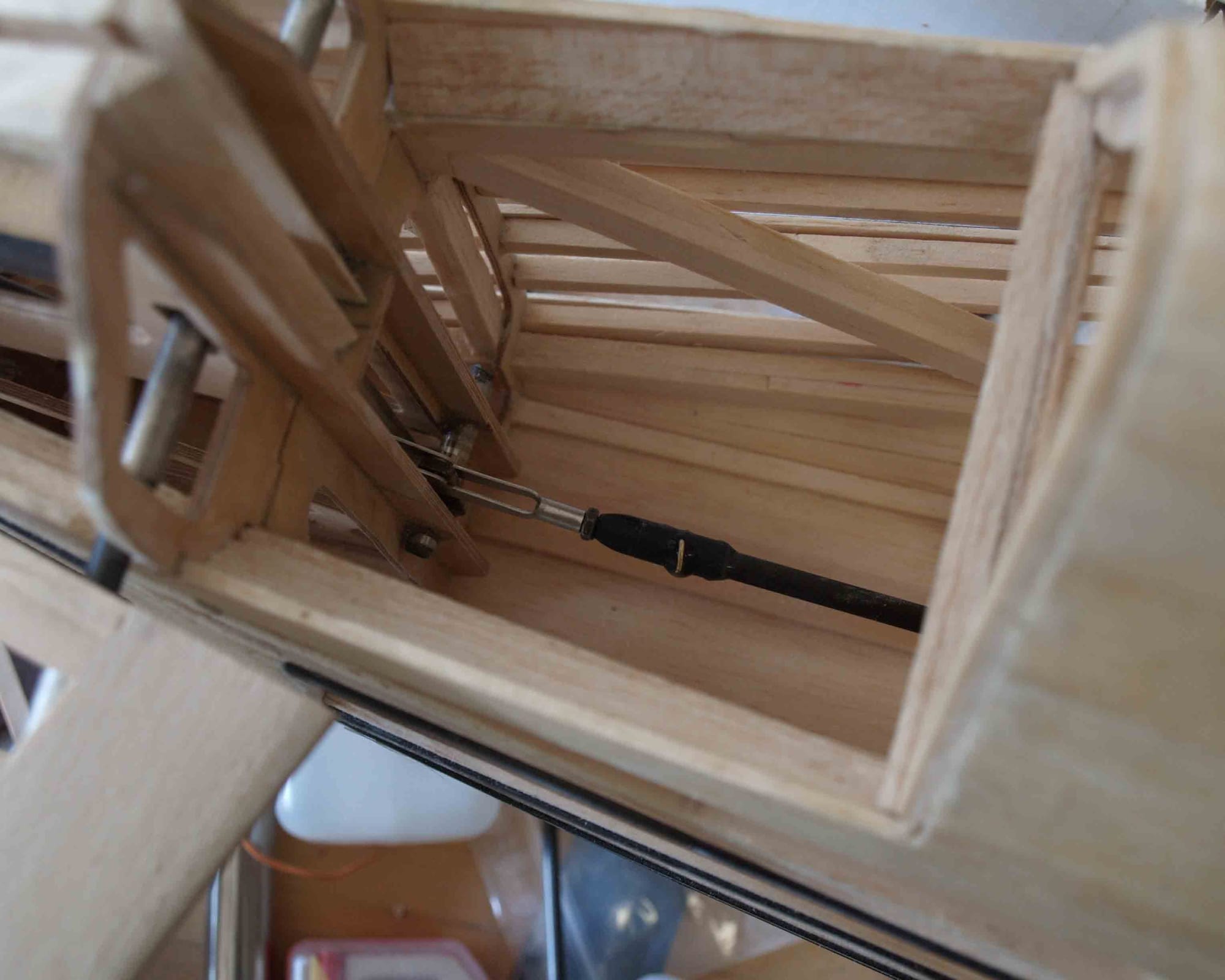
after that, I made the elevator push rod from carbon fiber
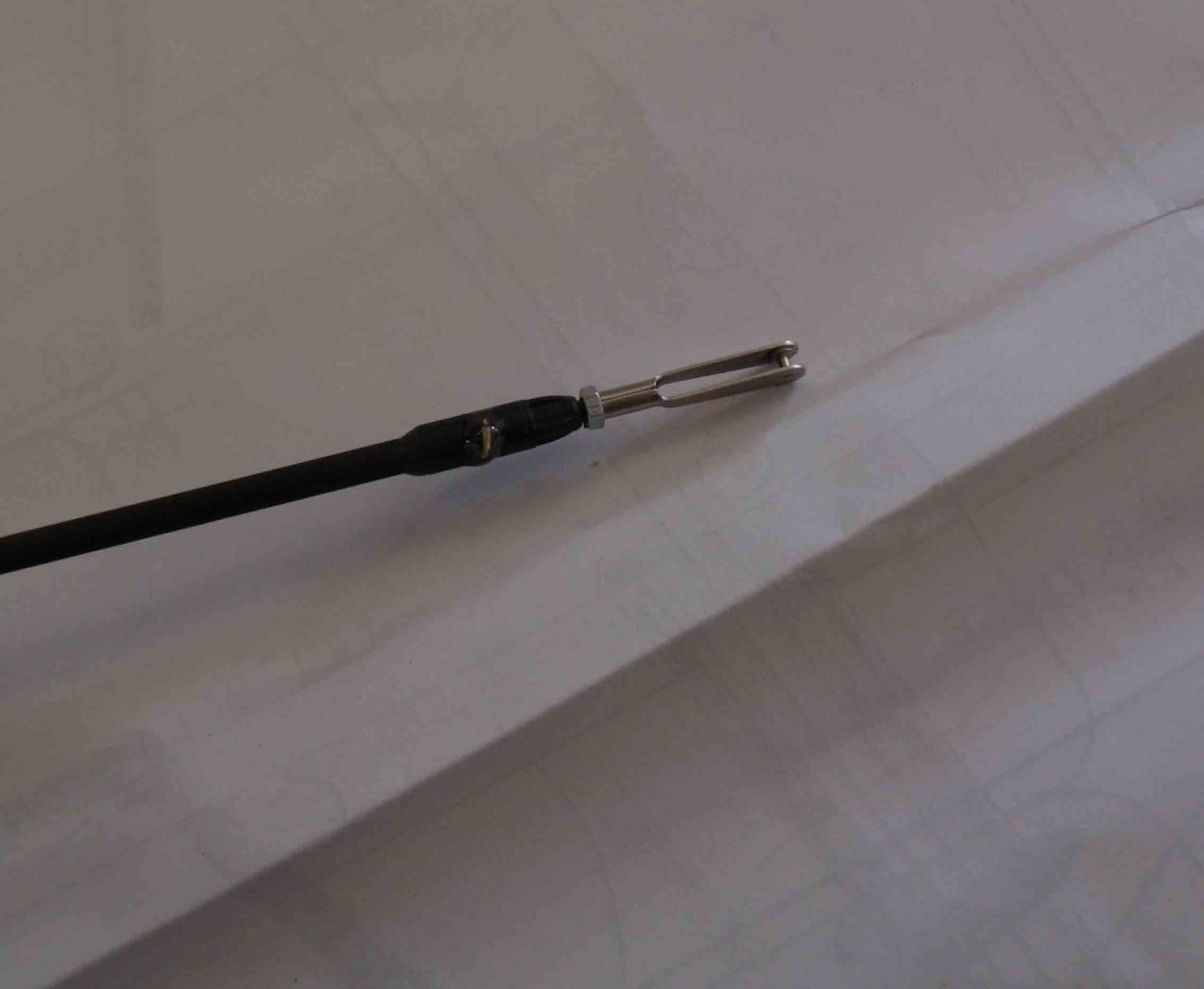
Elevator servo and rudder servo are done in place and the elevator push rod is installed.
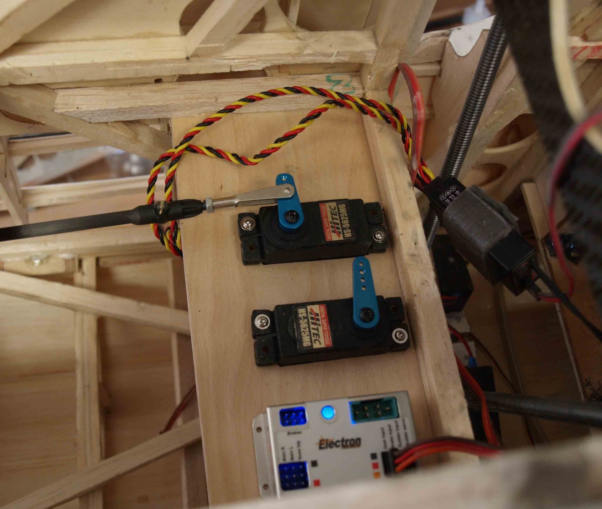
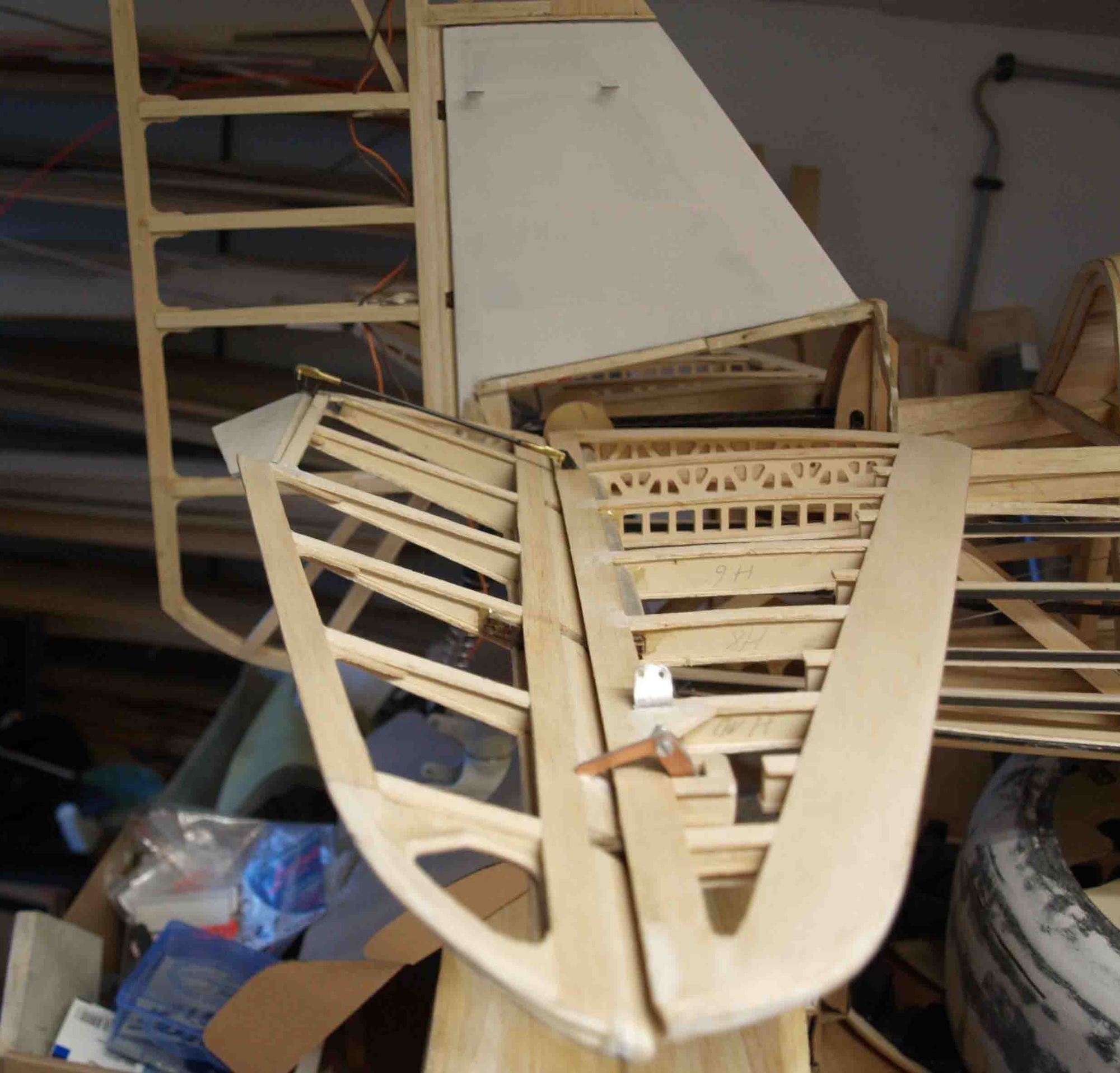
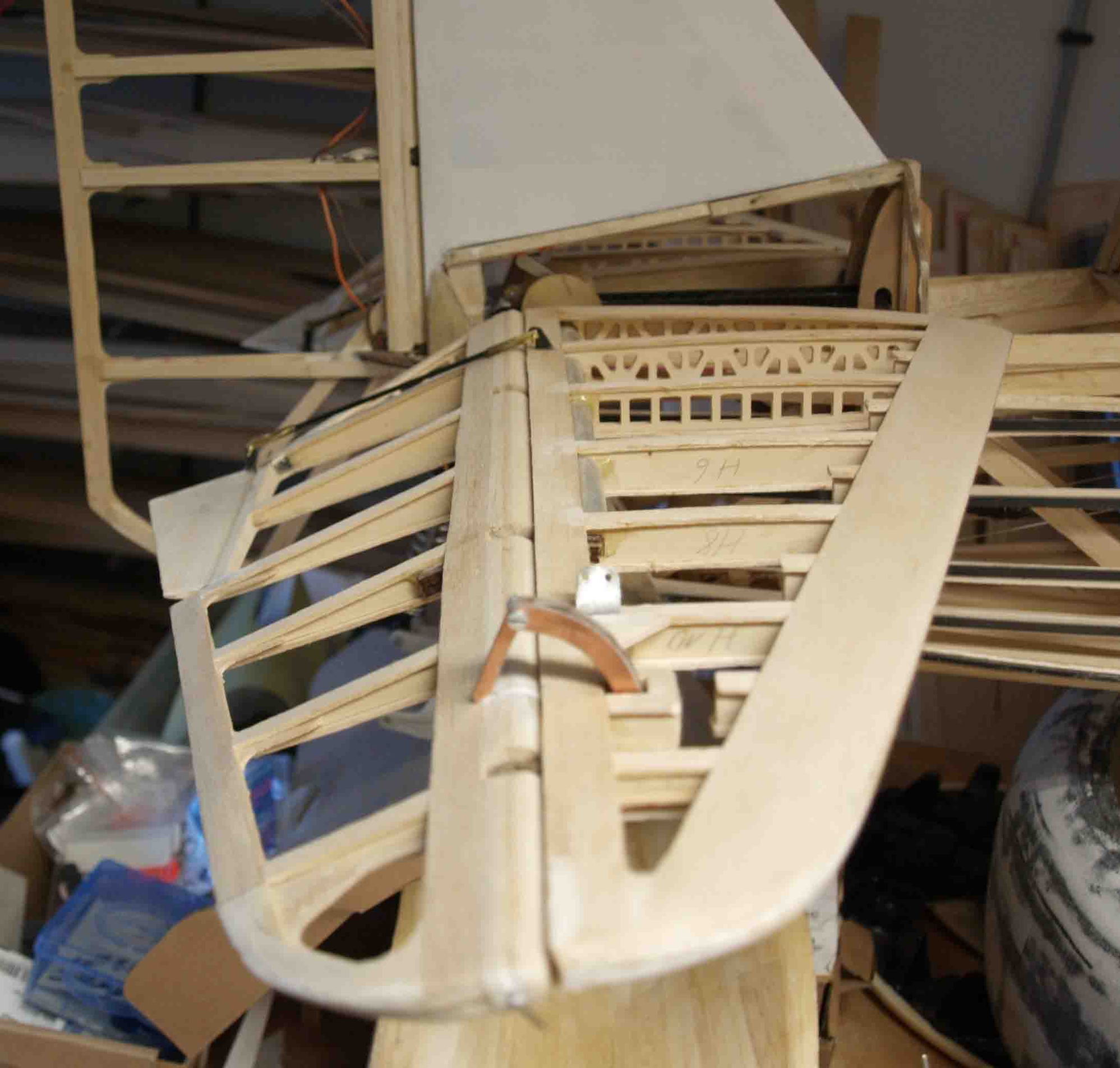
.Now it`s time for the rudder linkage. The problem was, I could`nt connect the rudder ropes and the tailwheel ropes at the same linkage horn. So I had to build a linkage bridge.
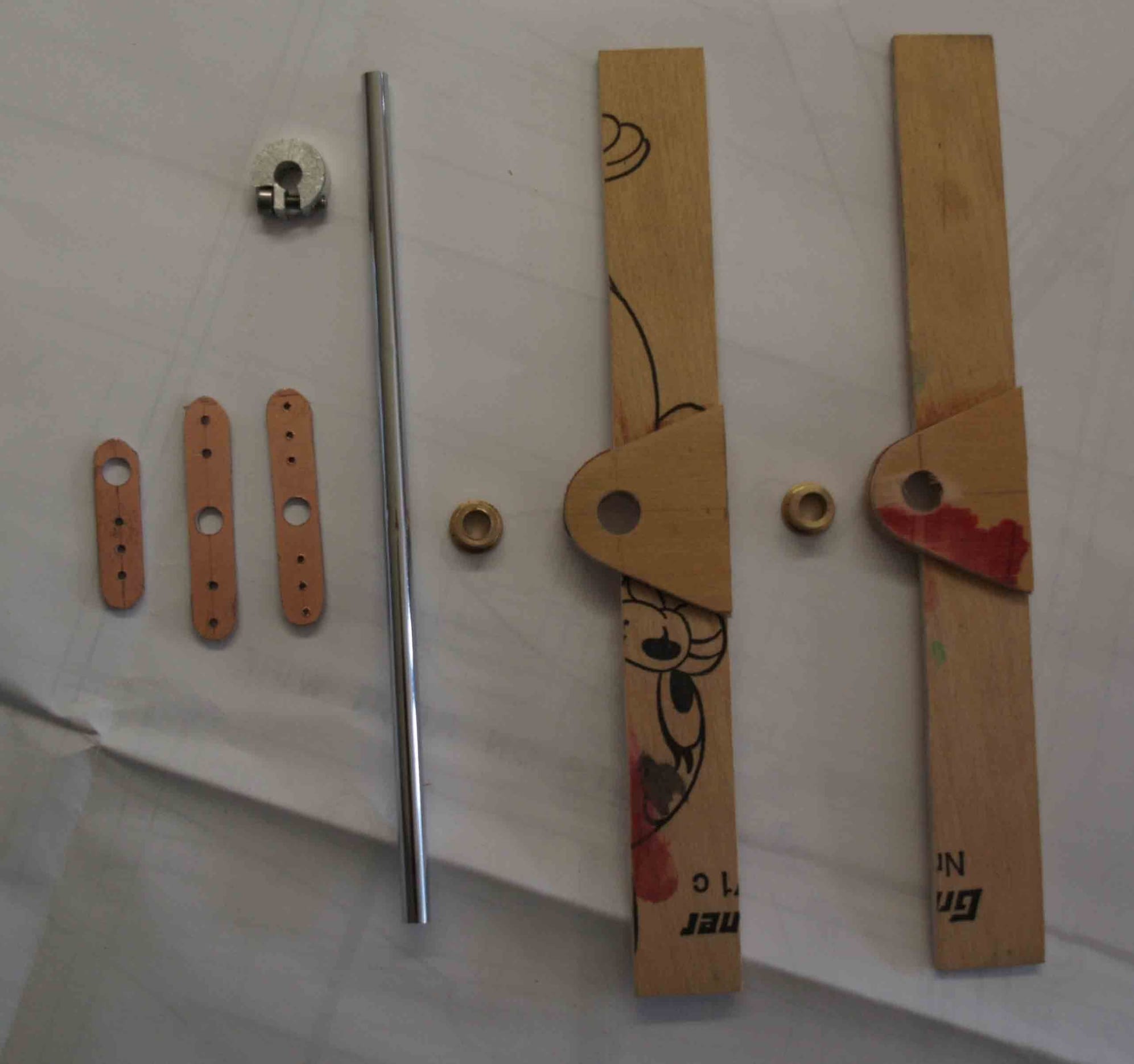
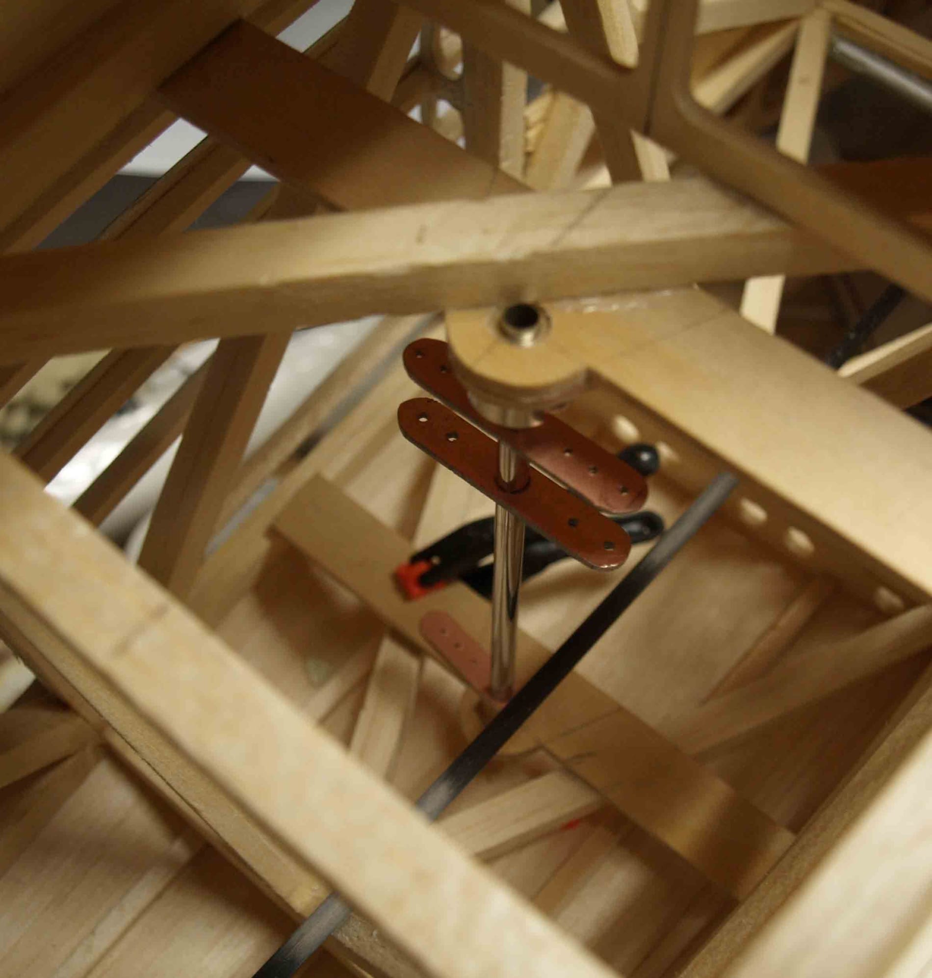
the upper horn is for the rudder, in the middle is the horn for the tail wheel and the lower horn is for the push rod. I think the pics says moore than any words, the springs I`ve added into the tail wheel ropes protecting the rudder servo.

After finishing the engine things, it`s time to start with the RC-equipment.
At first I`ve done the tail, starting with the tail wheel.
A friend of mine, owning a 3-d-printer made me the parts. I`ve done the metal work.
completed it looks so
now it`s added to the hull. I use a shockadsorber from an RC-car.
after that, I made the elevator push rod from carbon fiber
Elevator servo and rudder servo are done in place and the elevator push rod is installed.
.Now it`s time for the rudder linkage. The problem was, I could`nt connect the rudder ropes and the tailwheel ropes at the same linkage horn. So I had to build a linkage bridge.
the upper horn is for the rudder, in the middle is the horn for the tail wheel and the lower horn is for the push rod. I think the pics says moore than any words, the springs I`ve added into the tail wheel ropes protecting the rudder servo.
Last edited by thomasmuckus; 11-02-2019 at 12:45 PM.
 11-02-2019, 01:01 PM
#78
Thread Starter
Join Date: Jan 2014
Location: Eppendorf, Saxonia, Germany
Posts: 129
Likes: 0
Received 7 Likes
on
7 Posts
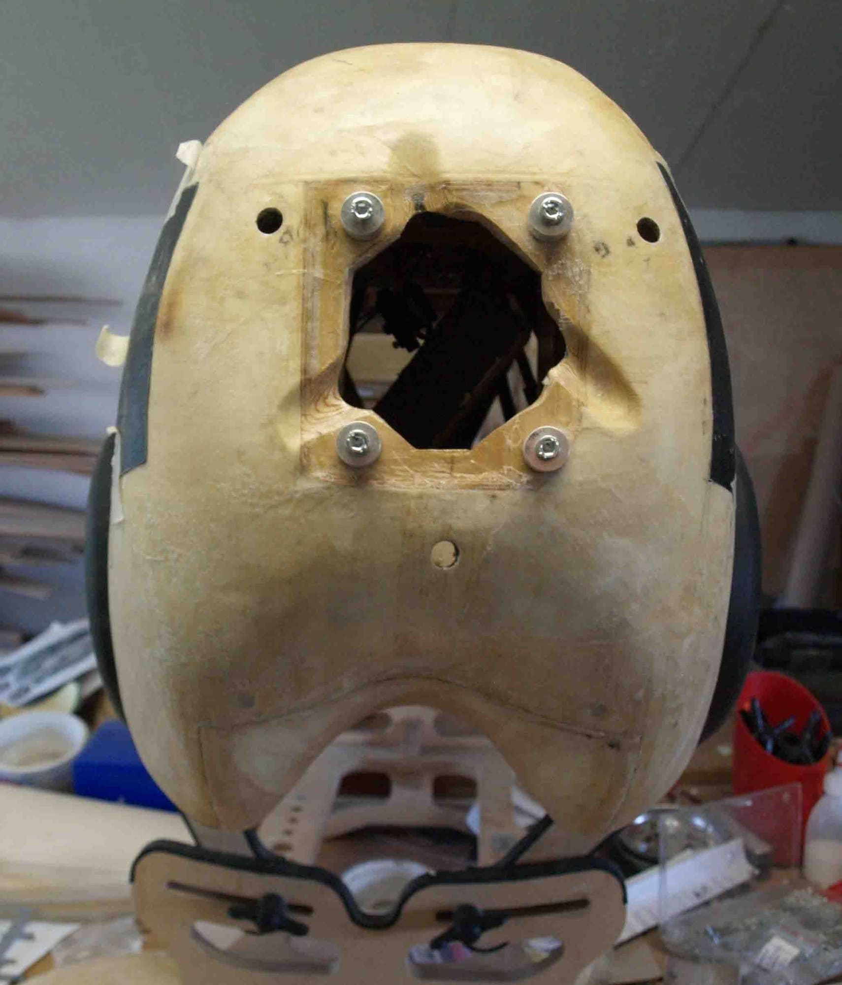
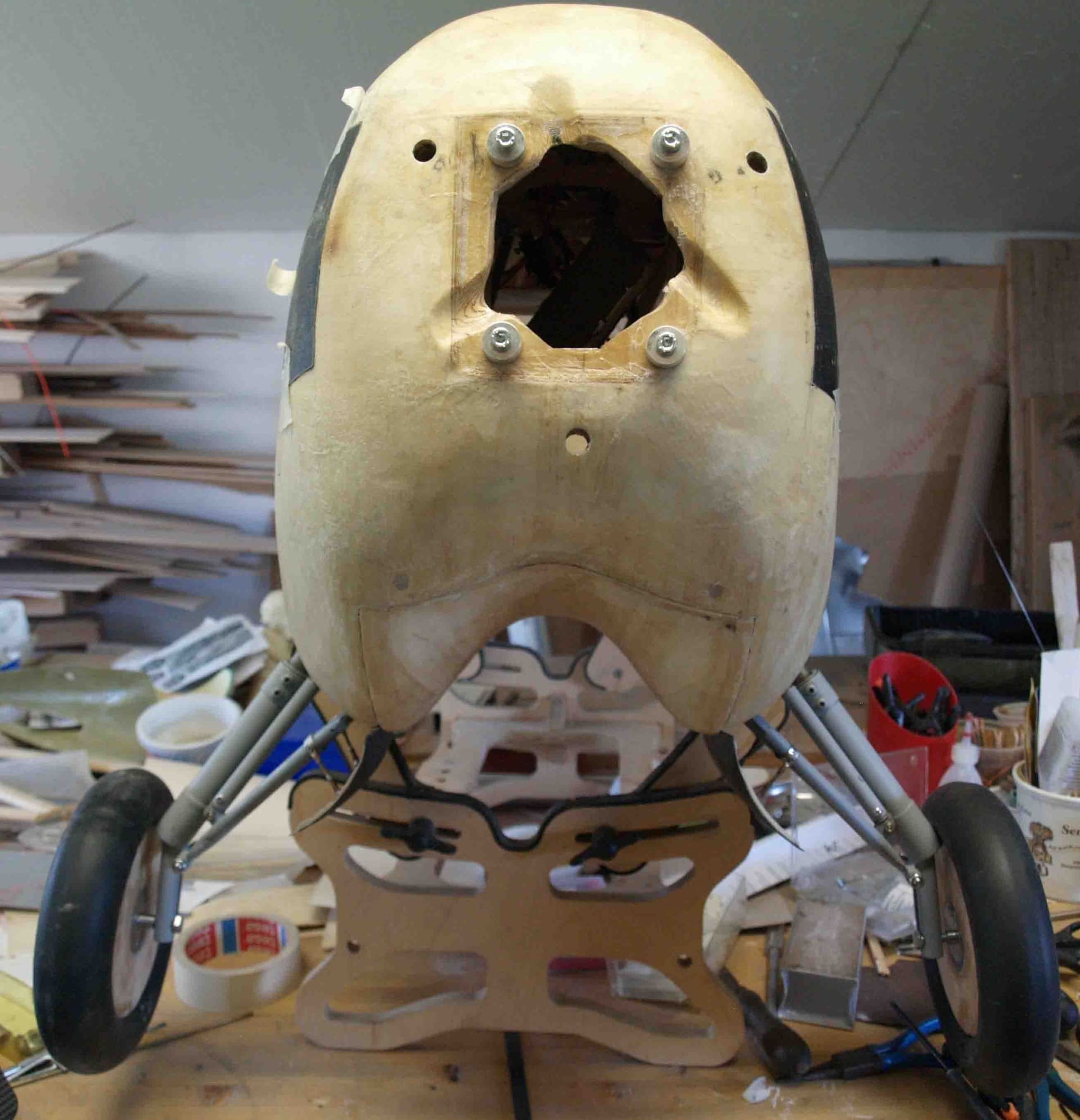
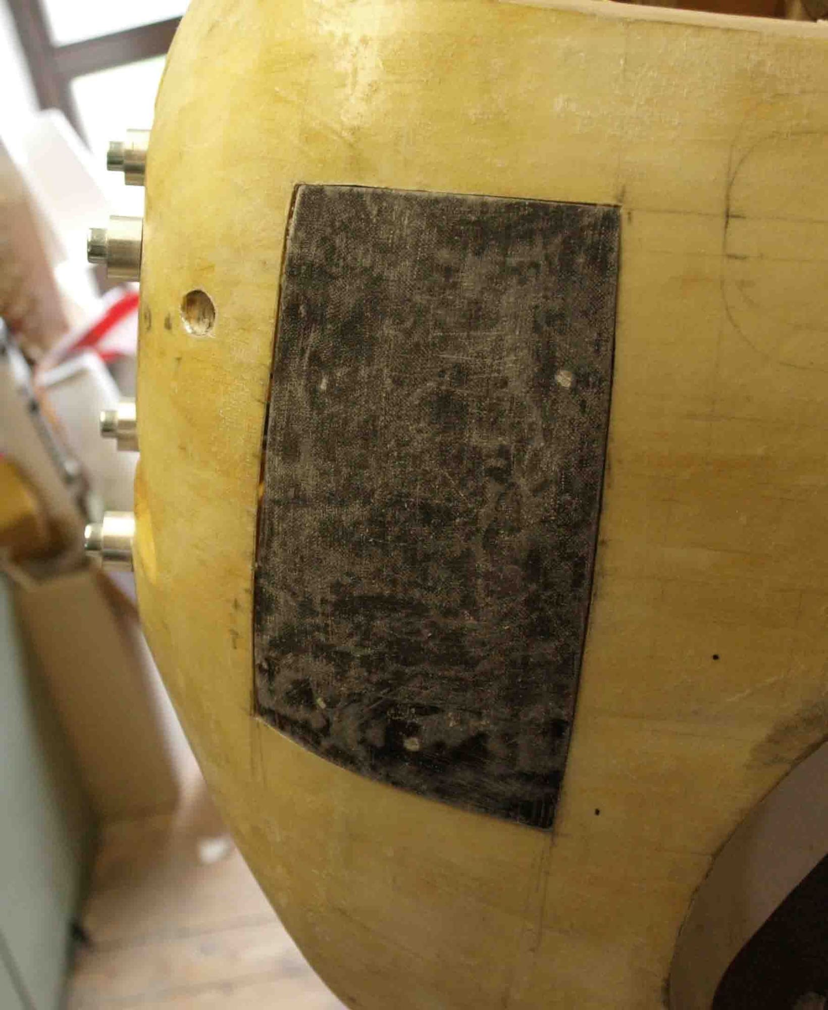
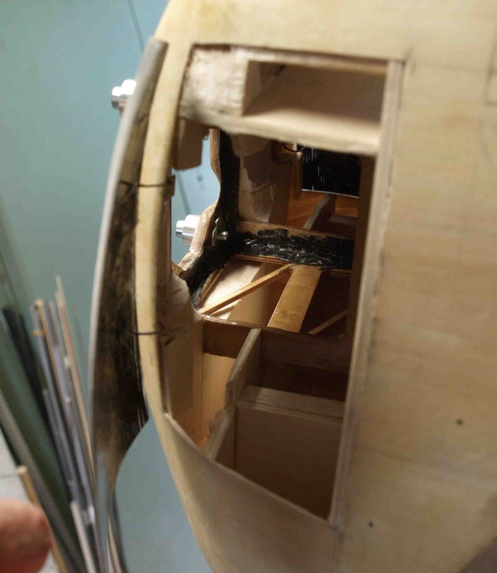
I`m really happy about my bis service holes, they allow me to work with booth hands into the fuse.
When they are closed and the fairing is added it looks pretty nice doesn`t it?
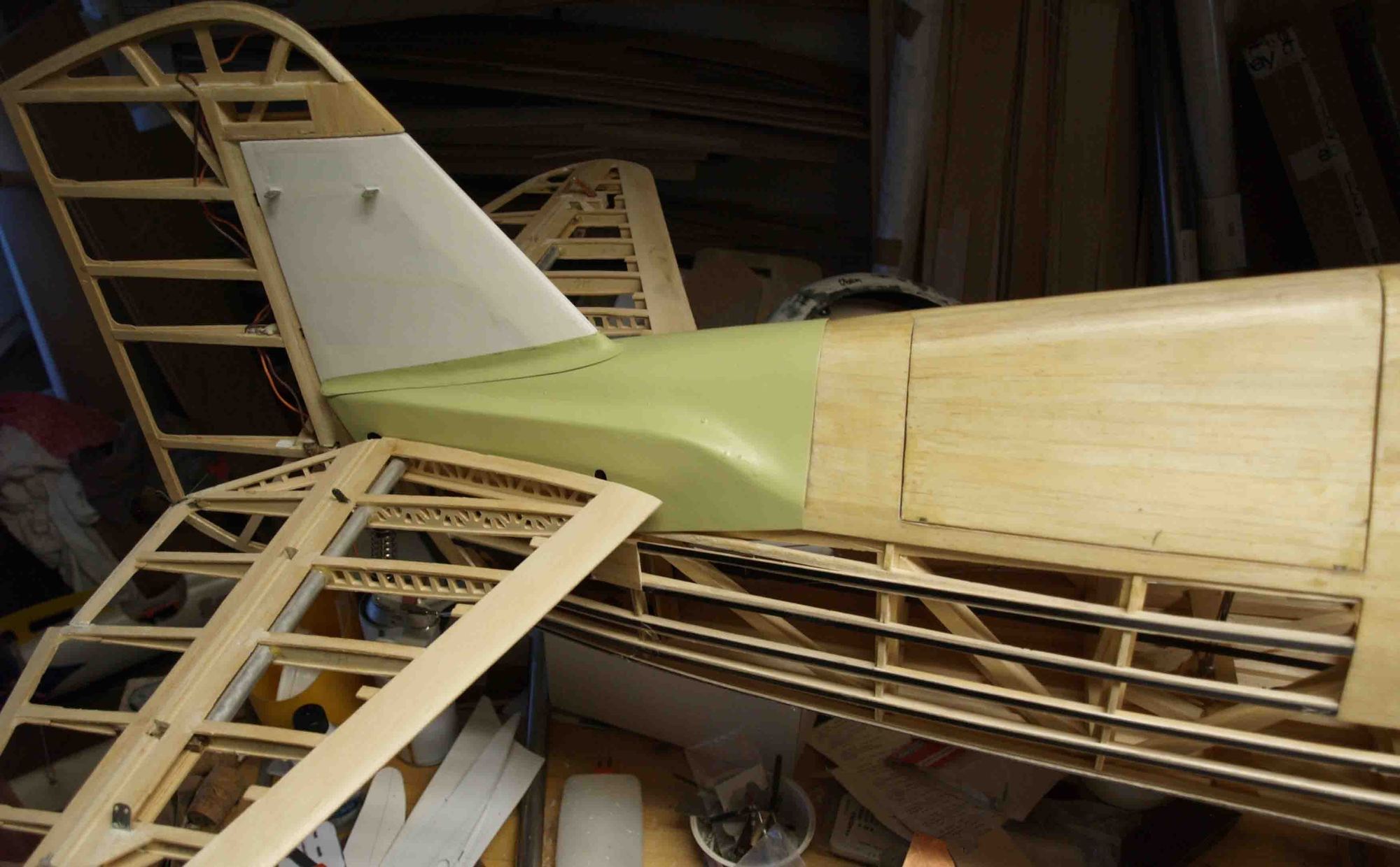
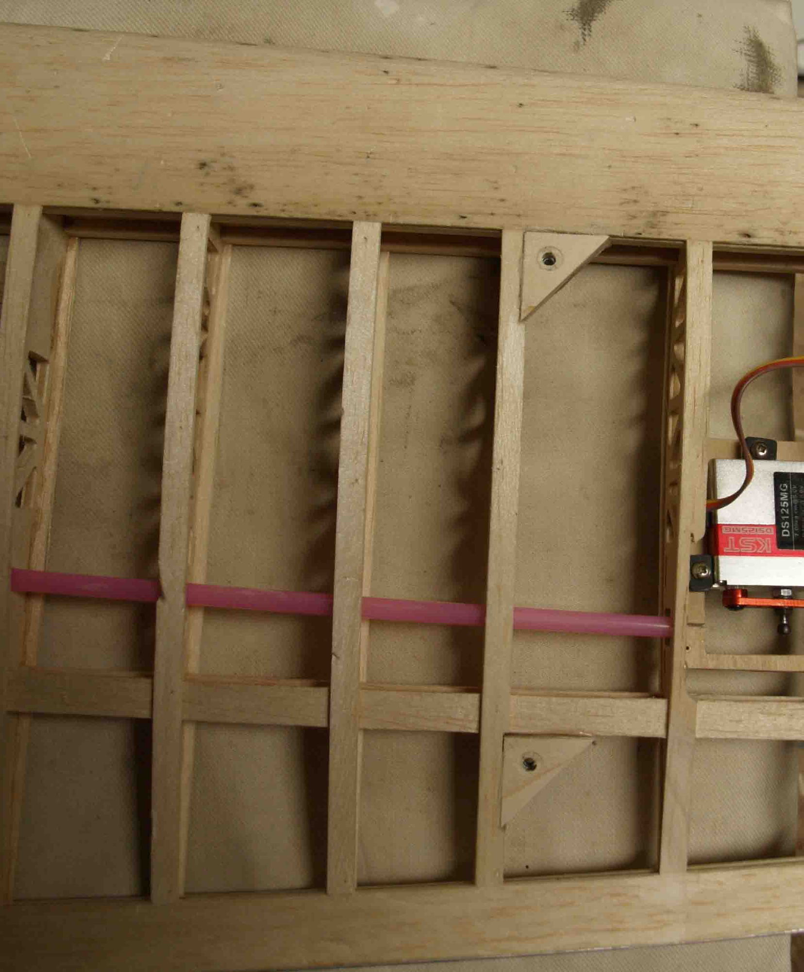
the next step is the linkage for the ailerons. At first I had inmy minds to do this like the original, shown in post 15. But, afte any talks with some of my buddies, I decided
to drive the ails directly. So I removed the linkage and added small but powerful servos.
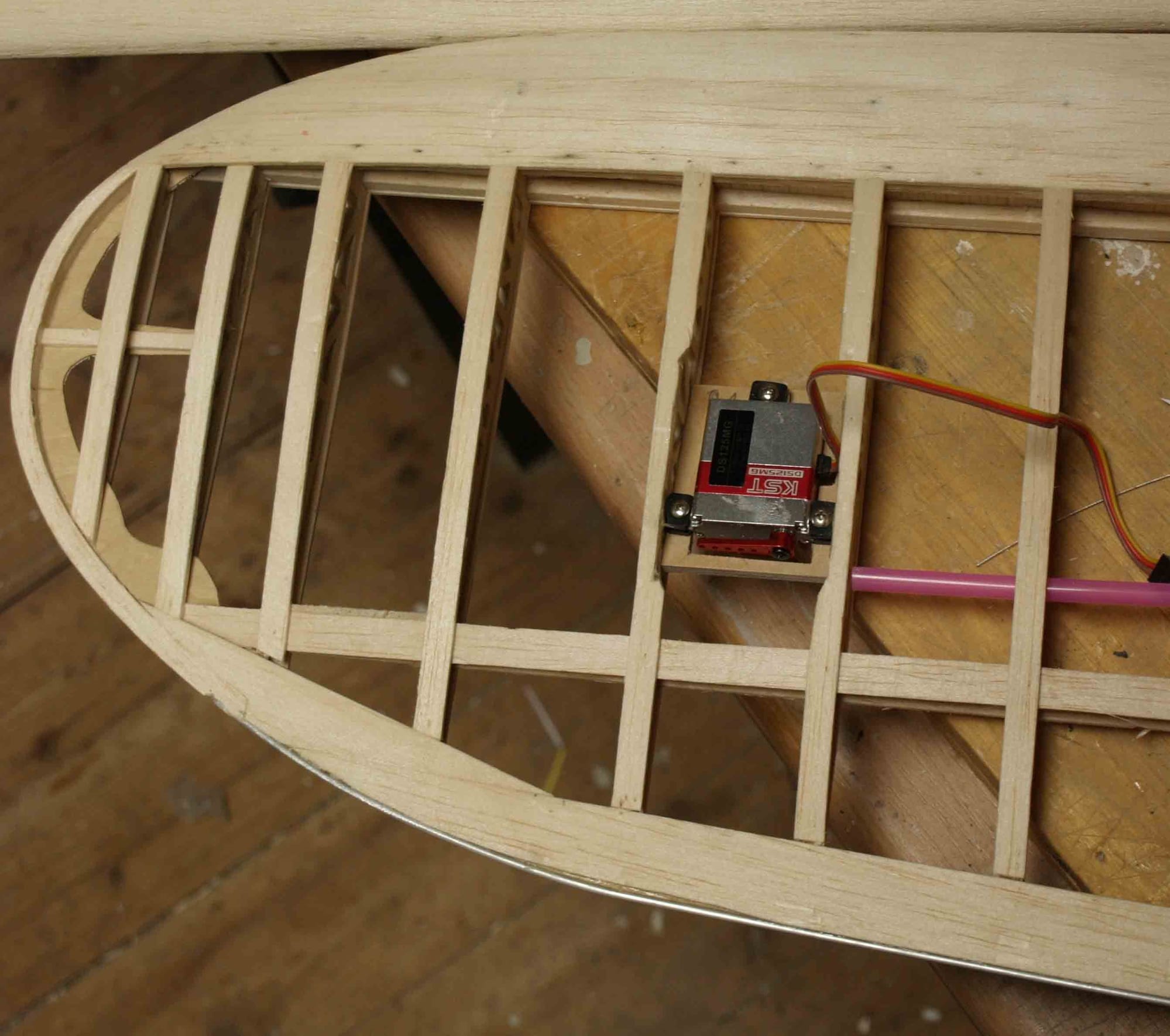
Now I made the hinges from "Novotex". It`s very strong and easy to handle.
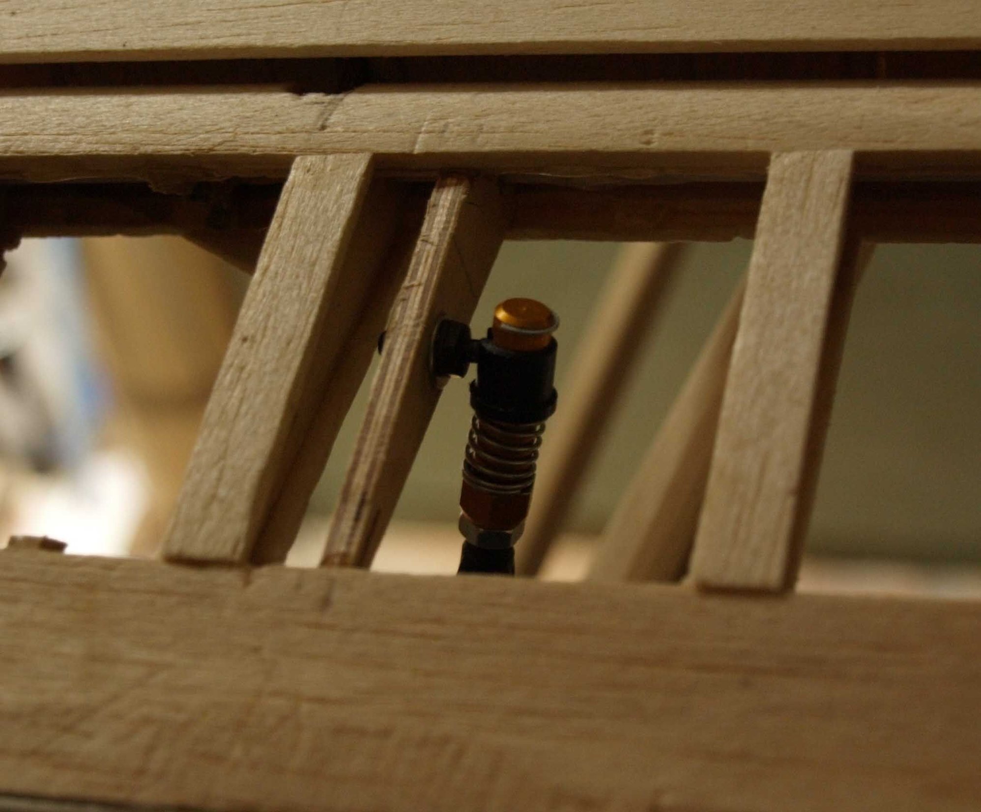
After gluing thr hinges in its place I made the aileron horns. I used solid airkraft plywood, with 5 layers for this. For the push rod I used Sullivan`s ball connectors, that makes the building off and up on the airfield easier.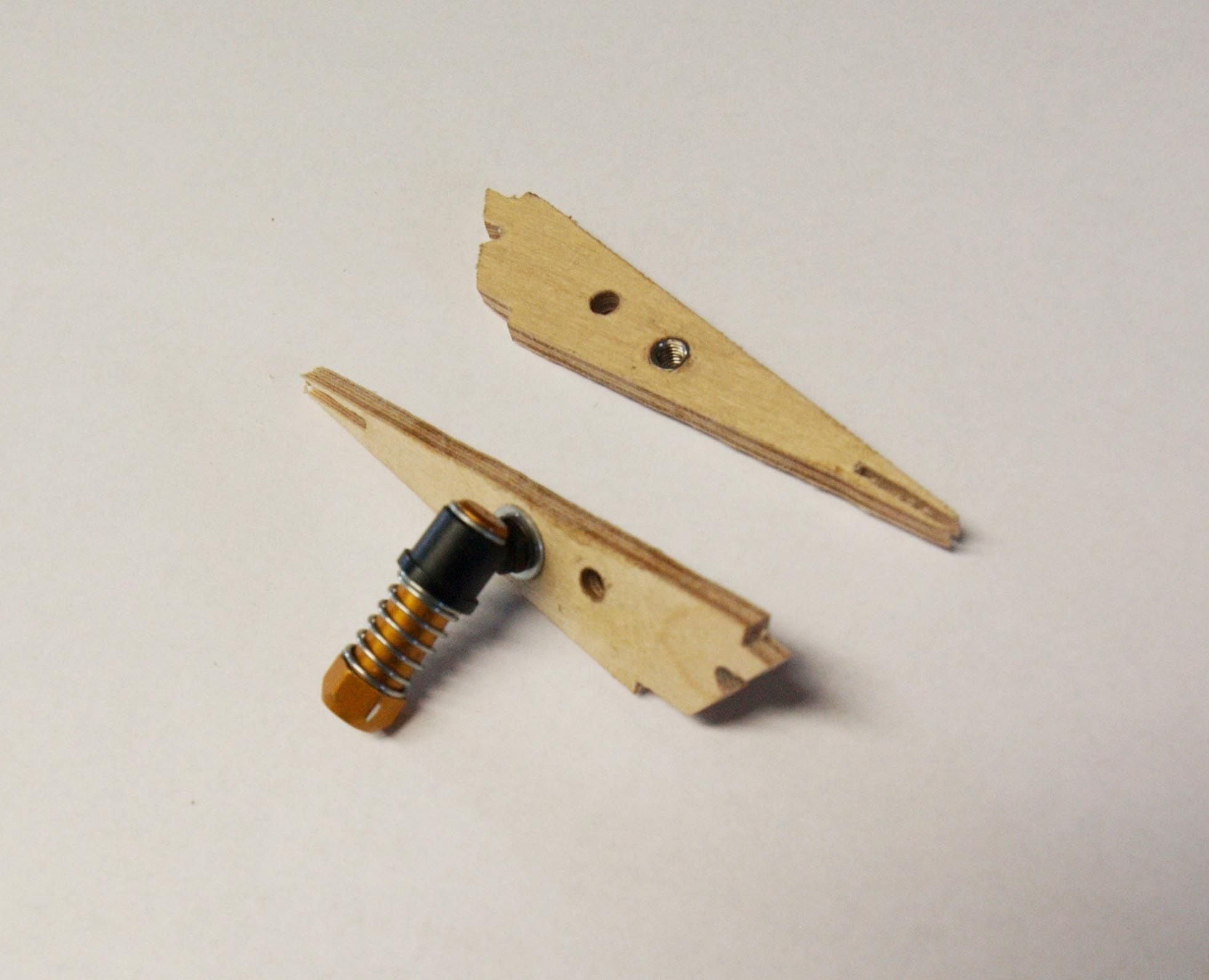

I`ll substitute the wooden pushrods to carbon fiber, I had to wait for delivery.
Not at all, the wooden rods are good enough to test the control surface, up and down.
When they are closed and the fairing is added it looks pretty nice doesn`t it?
the next step is the linkage for the ailerons. At first I had inmy minds to do this like the original, shown in post 15. But, afte any talks with some of my buddies, I decided
to drive the ails directly. So I removed the linkage and added small but powerful servos.
Now I made the hinges from "Novotex". It`s very strong and easy to handle.
After gluing thr hinges in its place I made the aileron horns. I used solid airkraft plywood, with 5 layers for this. For the push rod I used Sullivan`s ball connectors, that makes the building off and up on the airfield easier.
I`ll substitute the wooden pushrods to carbon fiber, I had to wait for delivery.
Not at all, the wooden rods are good enough to test the control surface, up and down.
Last edited by thomasmuckus; 11-02-2019 at 01:16 PM.
01-05-2020, 01:37 PM
#80
Thread Starter
Join Date: Jan 2014
Location: Eppendorf, Saxonia, Germany
Posts: 129
Likes: 0
Received 7 Likes
on
7 Posts
At first > a happy new year to everybody
@ warrenmiller > I only own an Opel Astra Sports Tourer, not the biggest car but it will be big enough. The longest part, the fuselage, is nit longer than 1700 mm, the wings are shorter than one meter. I have a princip > no more cylinder capacity than 60 cm� and no bigger car for models than a "normal" combi.
So, the building continued.
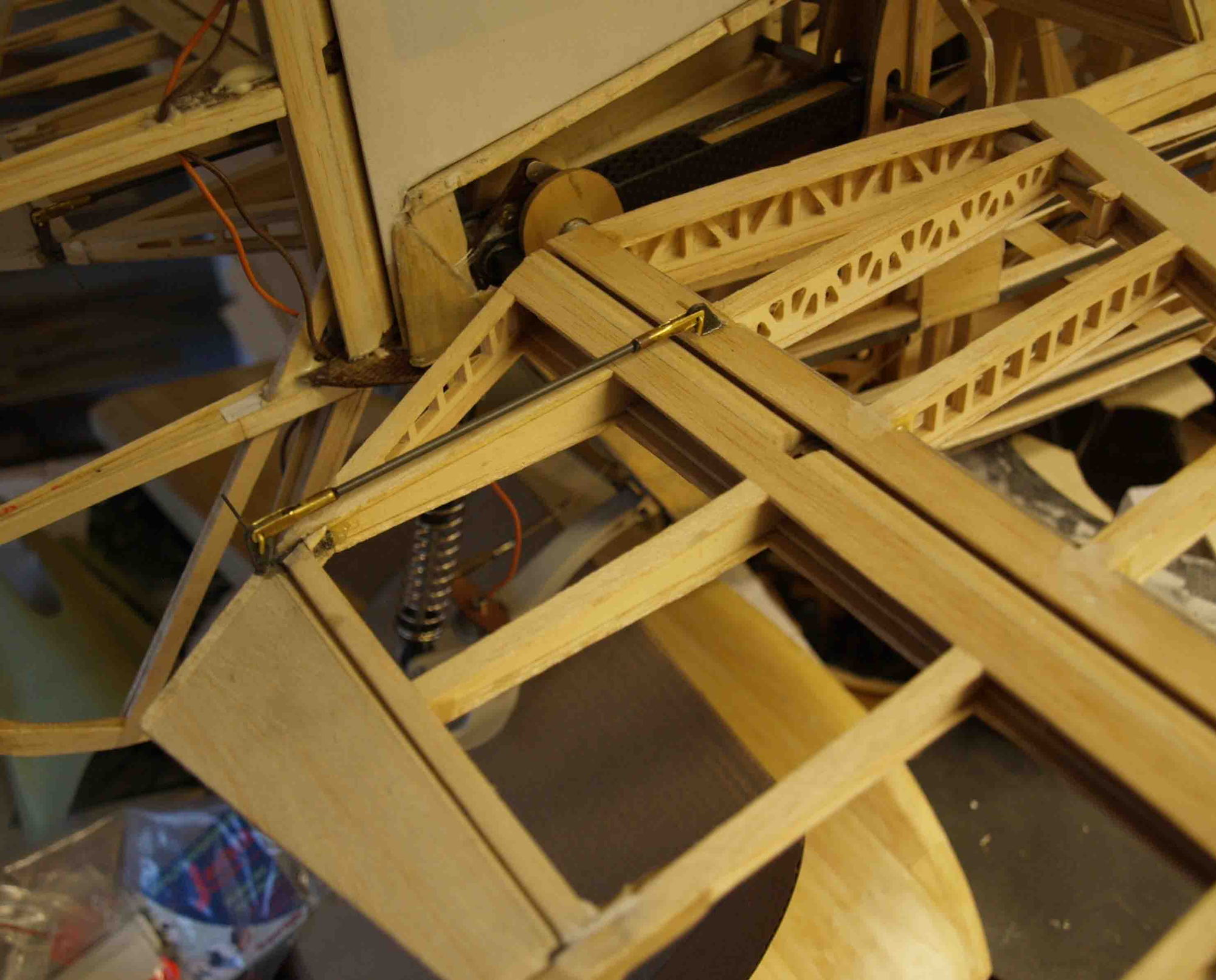
As next, I had to build the pushrods for the"Flettner"-flaps at the elevator.
I took some brass tube and cutted a small slit in it.

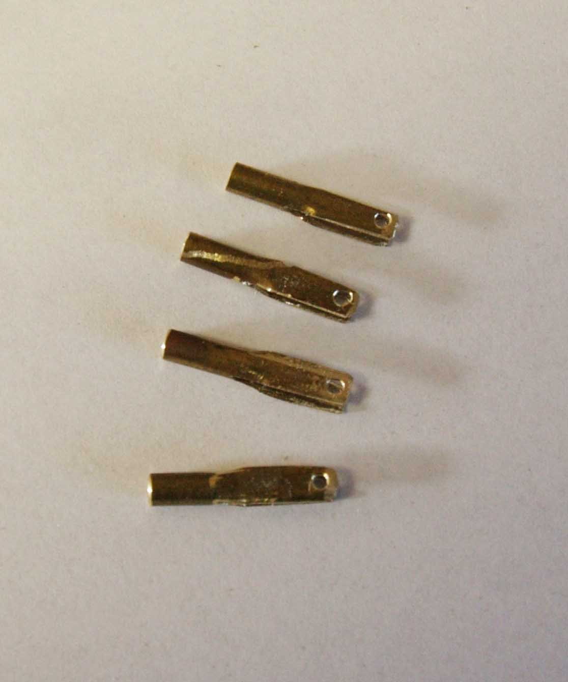
the push rod is made from carbon fiber
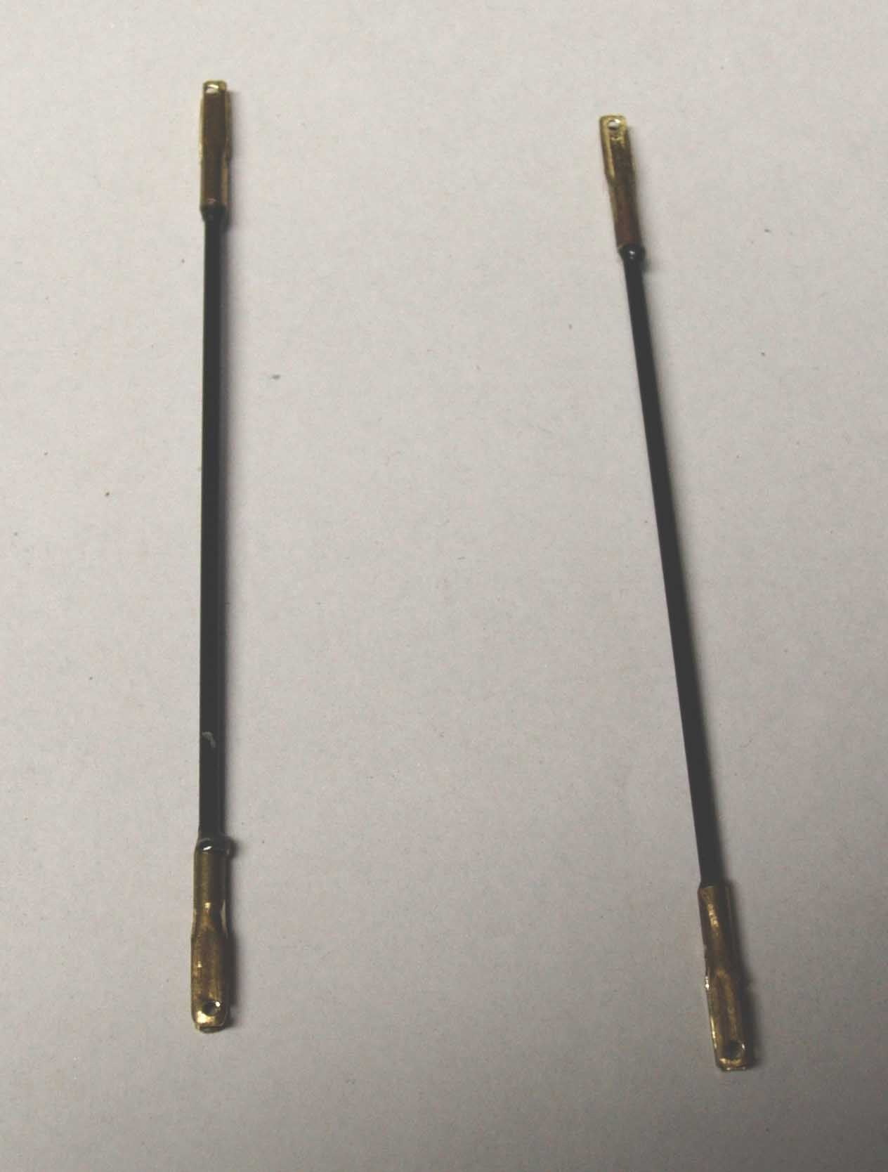
and so it works
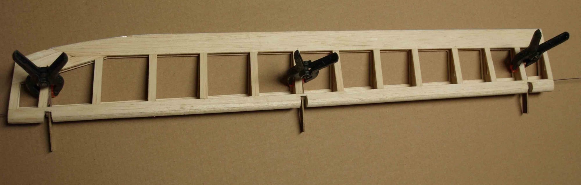
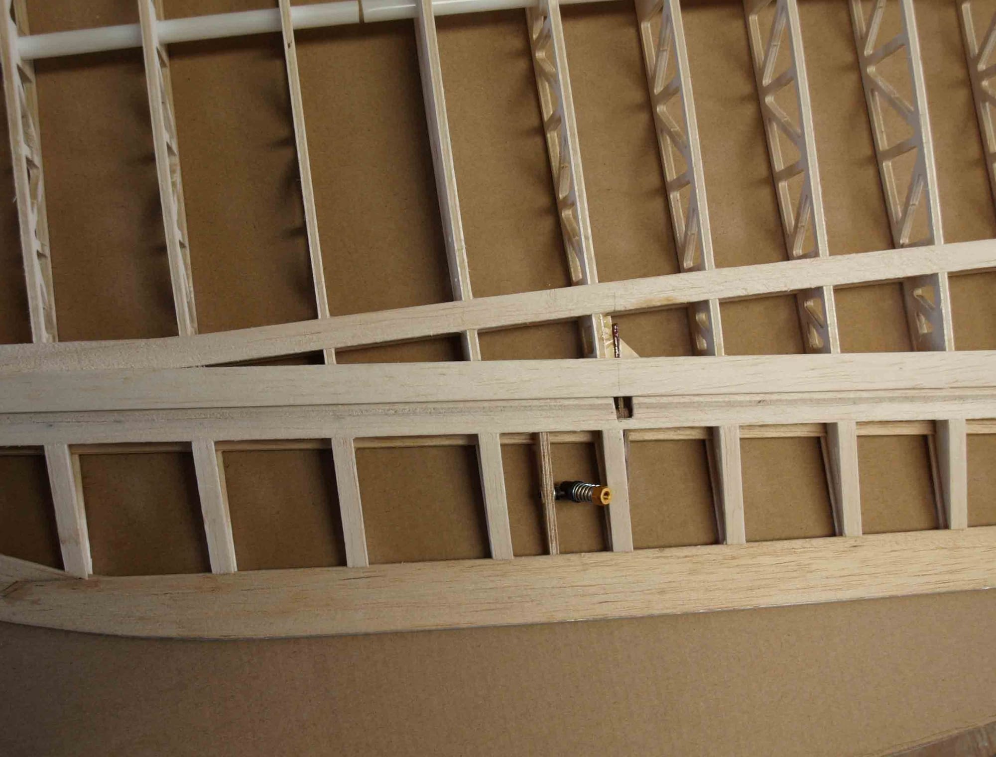
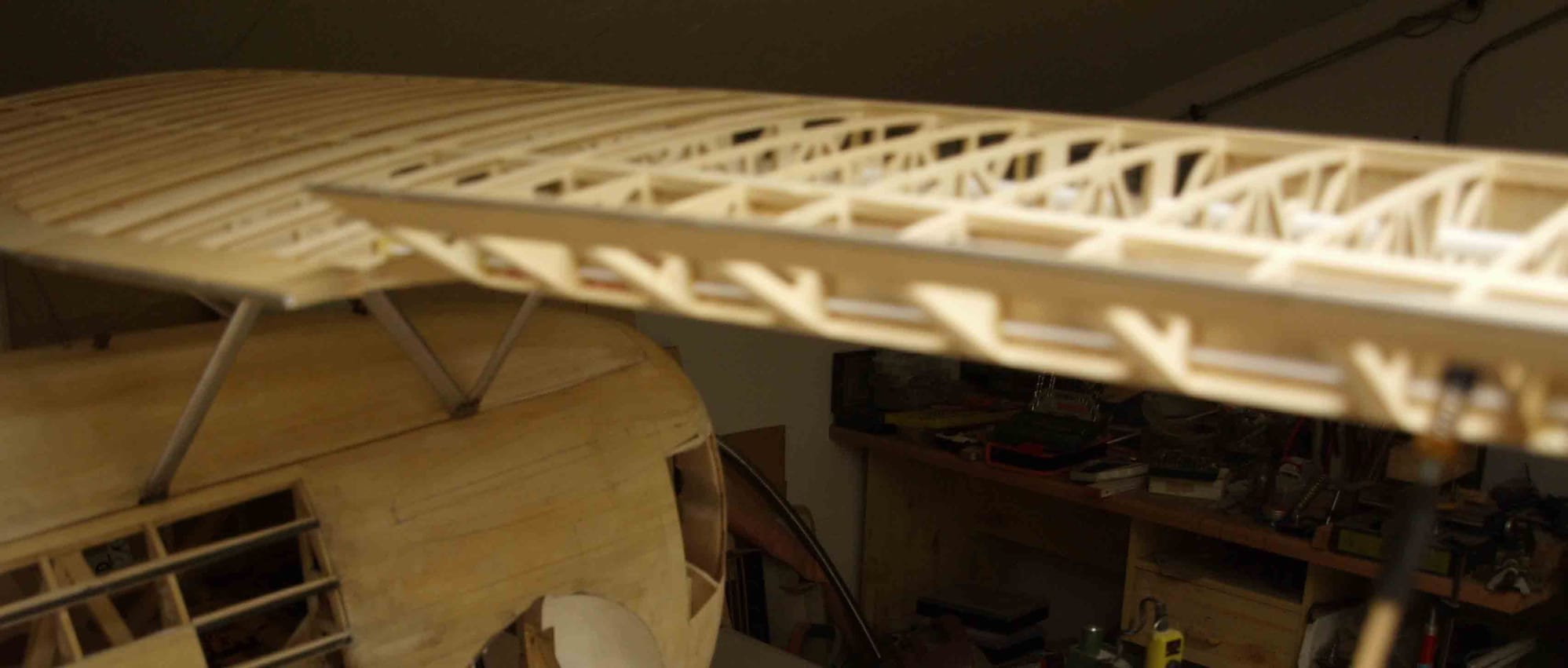
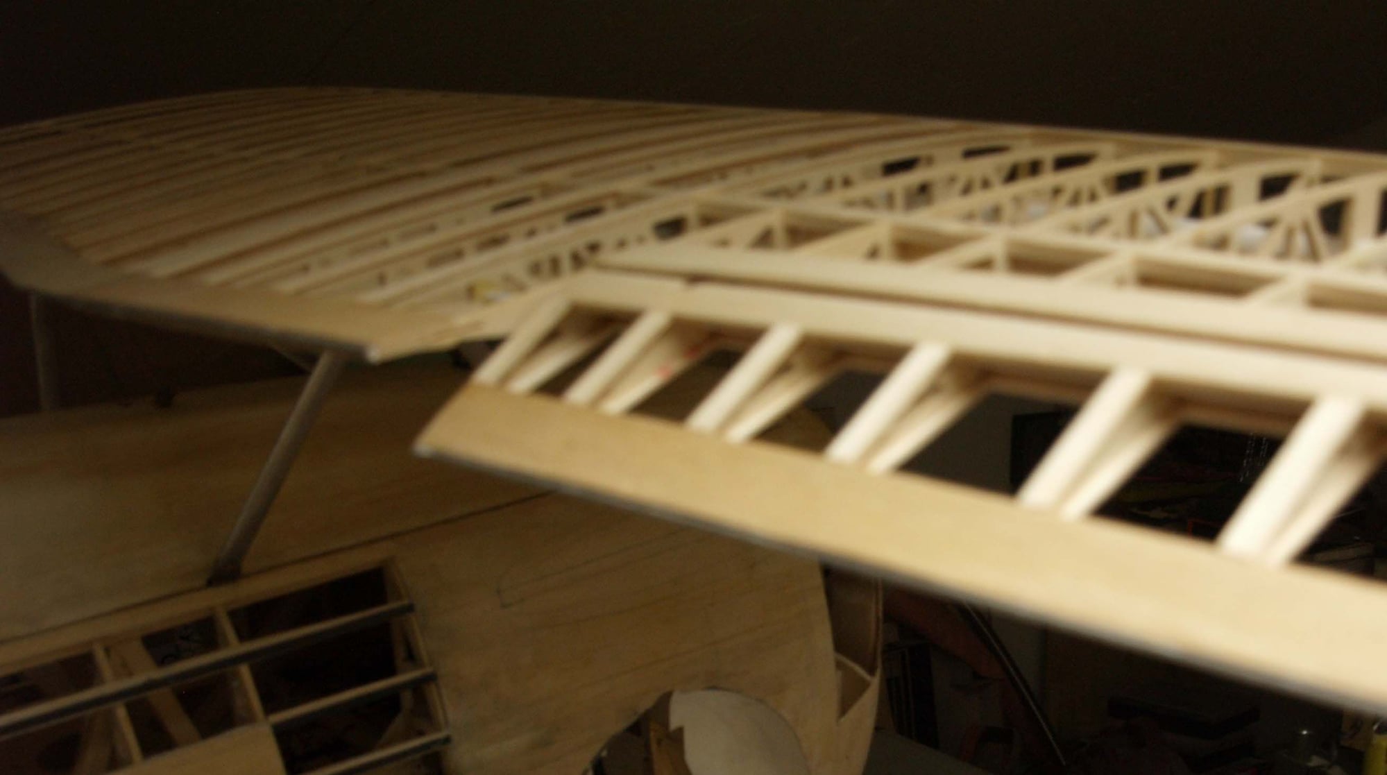
Now to the wing struts. The objective target was to make them quick removable and that the flying wires should be easy to handle too.
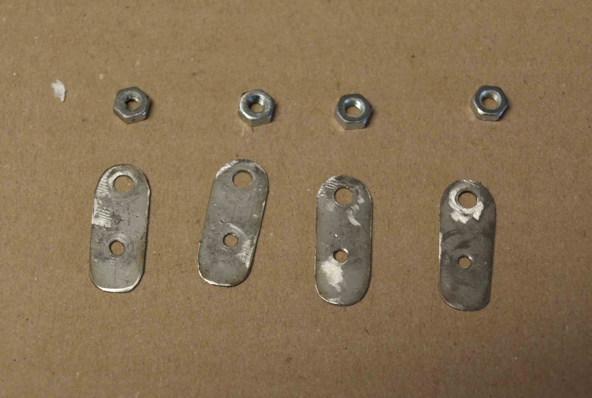
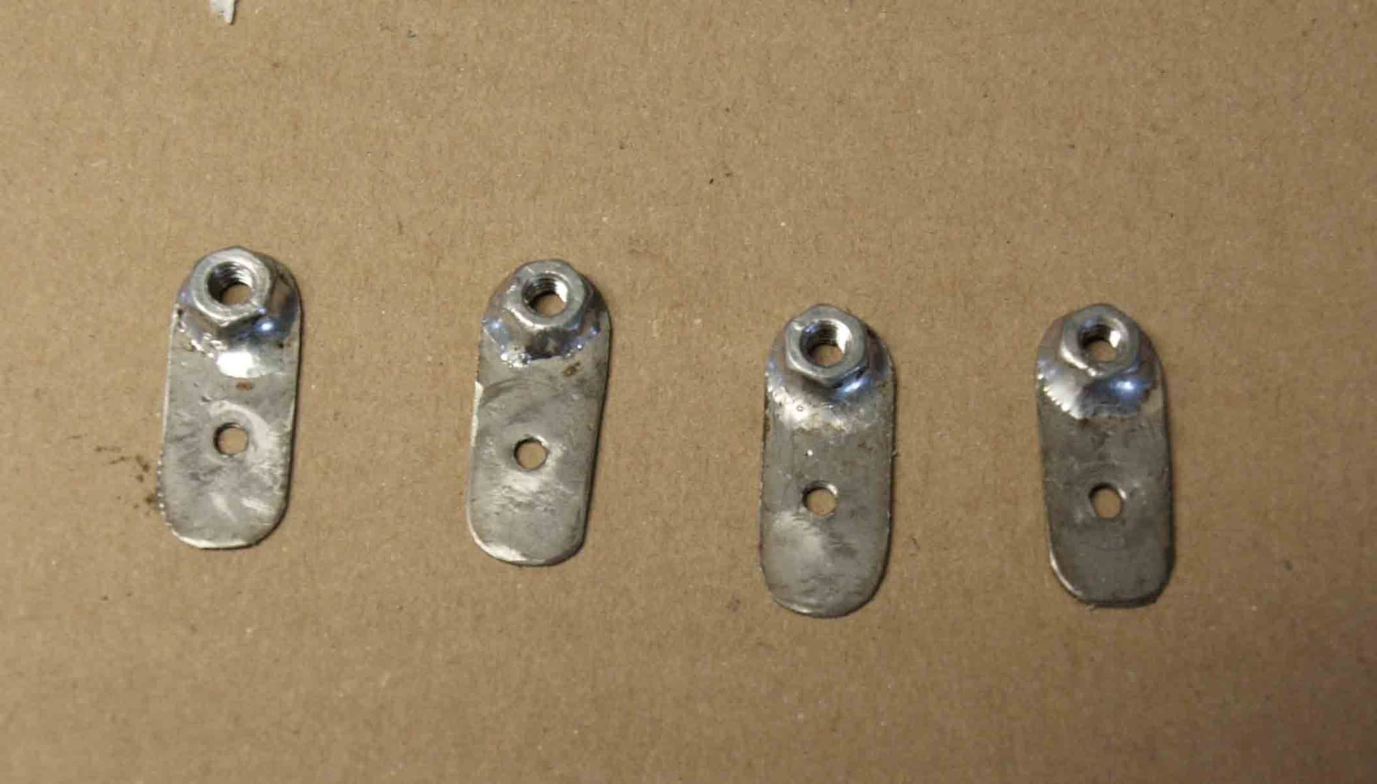
I started with the basic points, made from 4 mm plywood with nuts inside

glued in place into the lower wing
and the upper wing
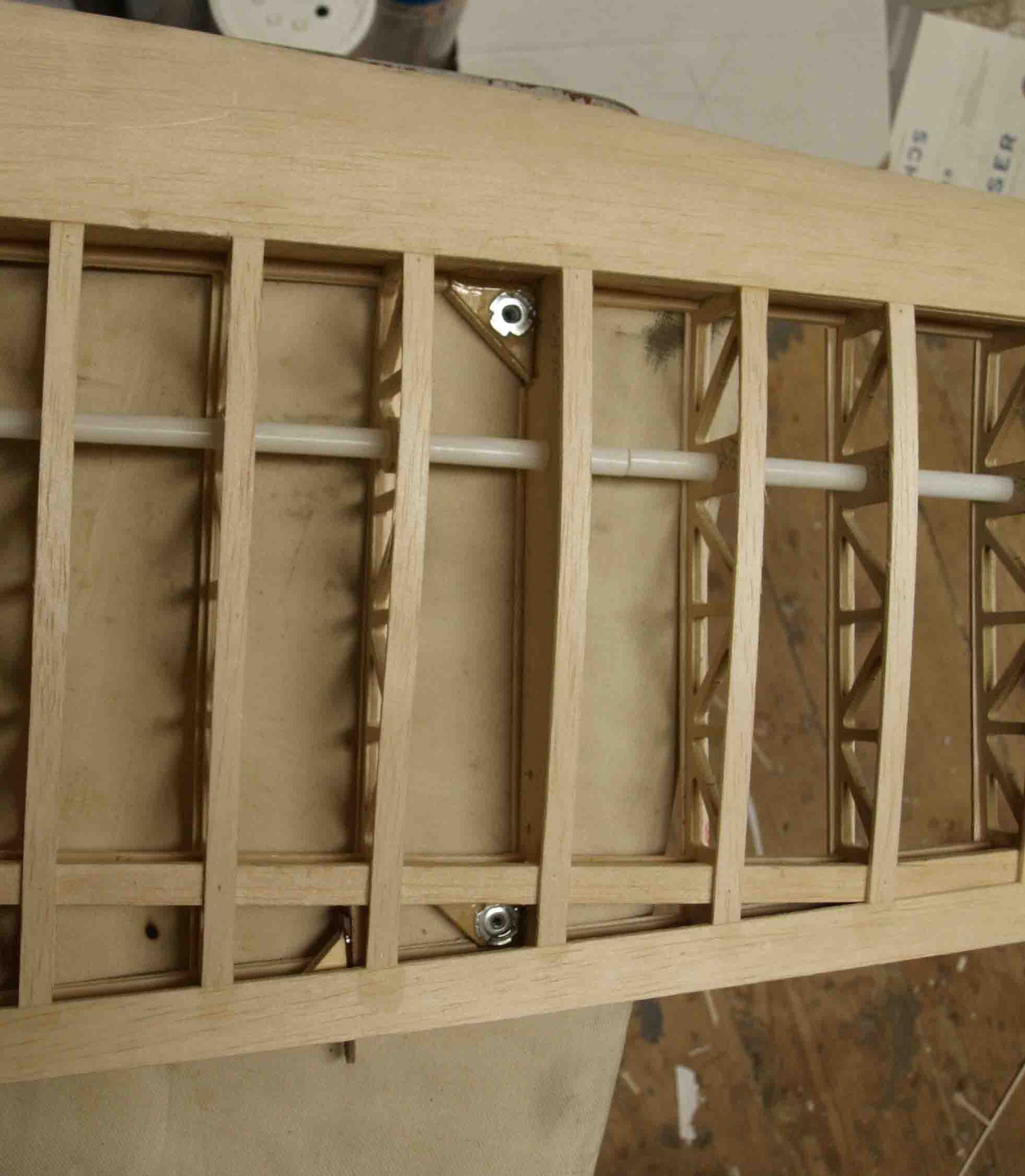
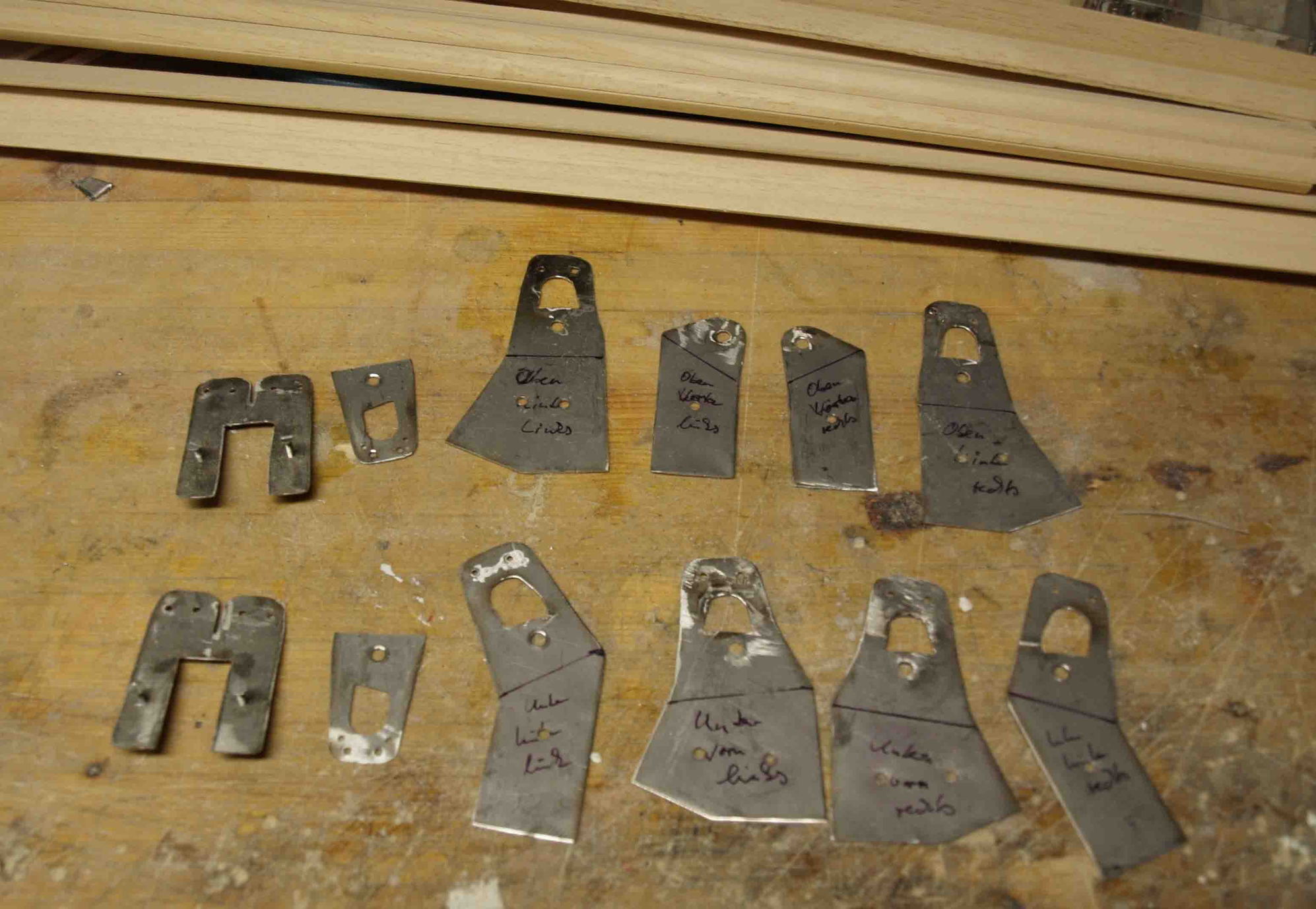
the next ste was to do some metal work, the fittings that hold the struts in place and also pick up the flying wires.
with some small strip I found out the right length for the struts.
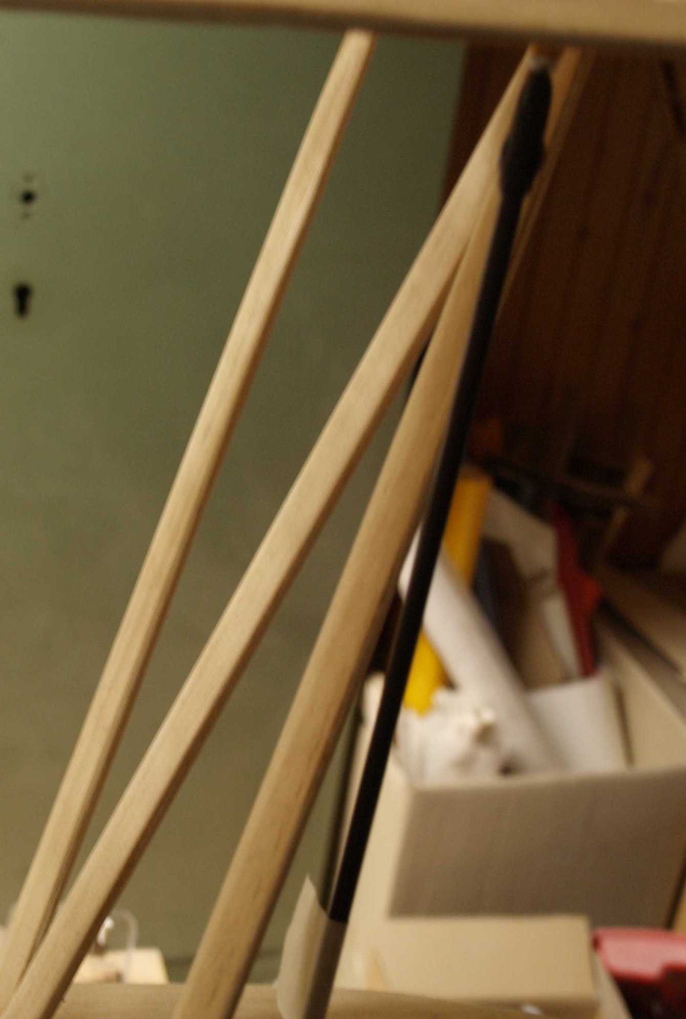
the real struts are made from profiled abachi strips
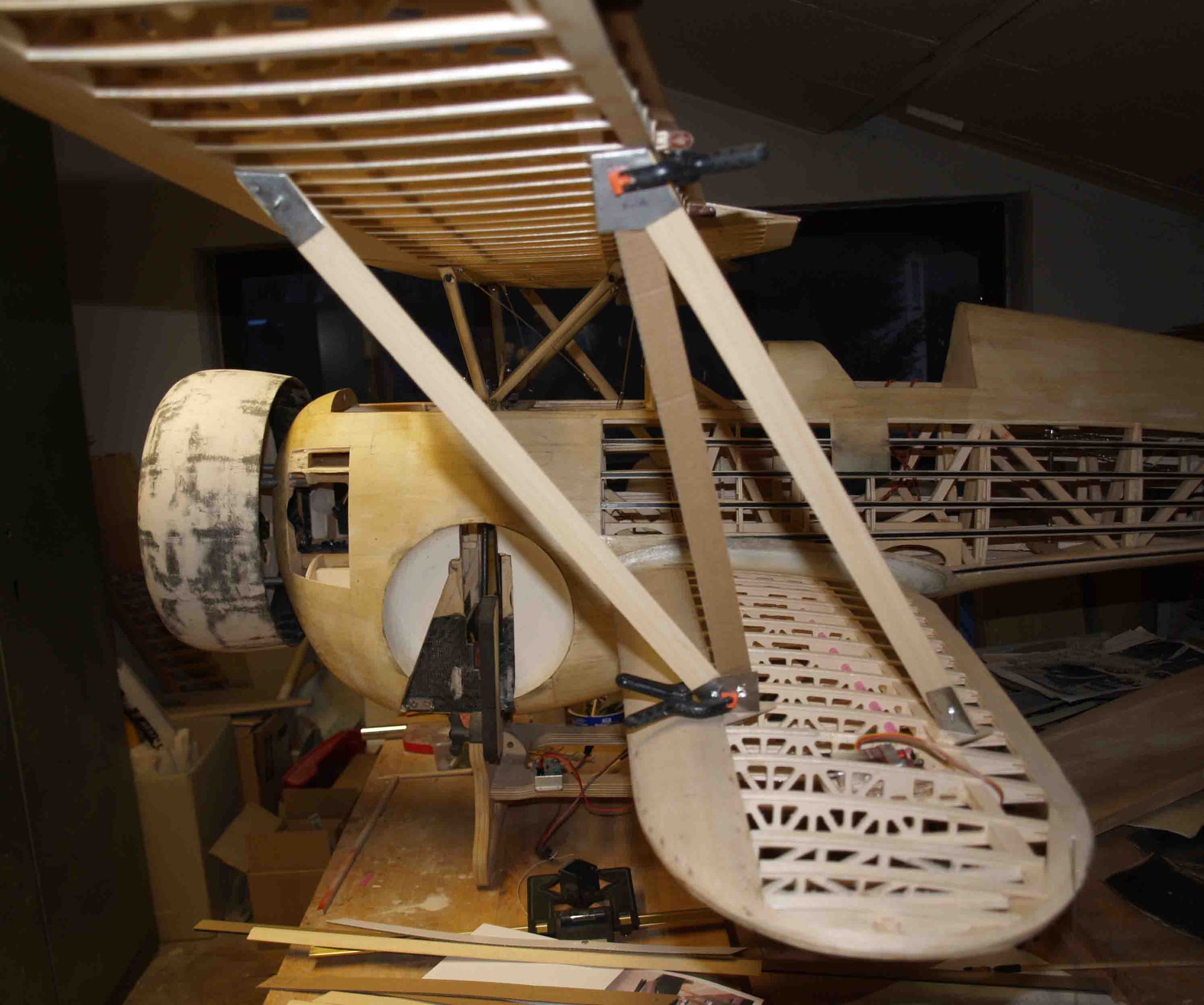
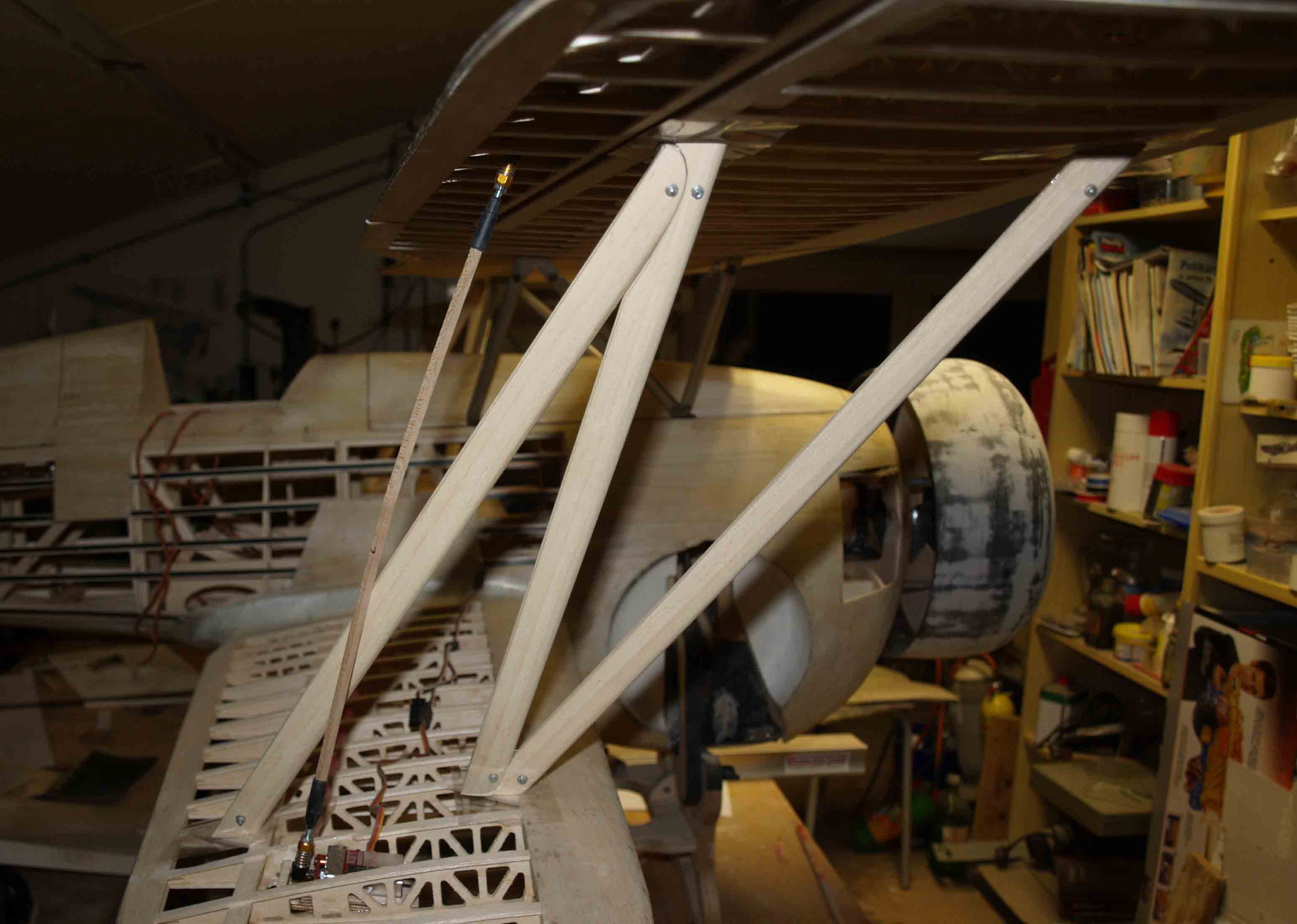
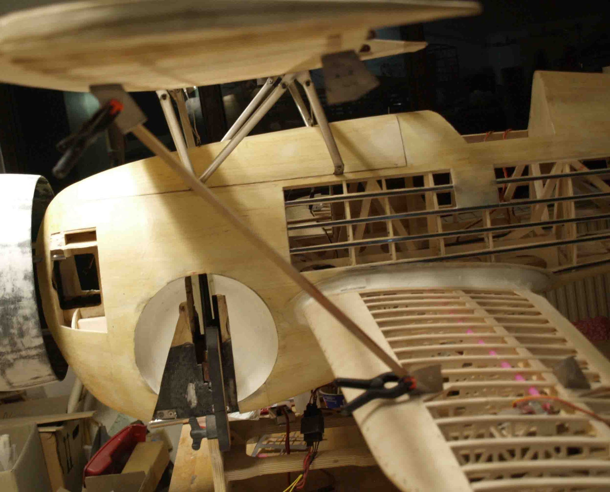
I`ve done a mistake when I glued the upper linkage for the aileron push rod, it doesnt work free (it was to close to the wing strut)
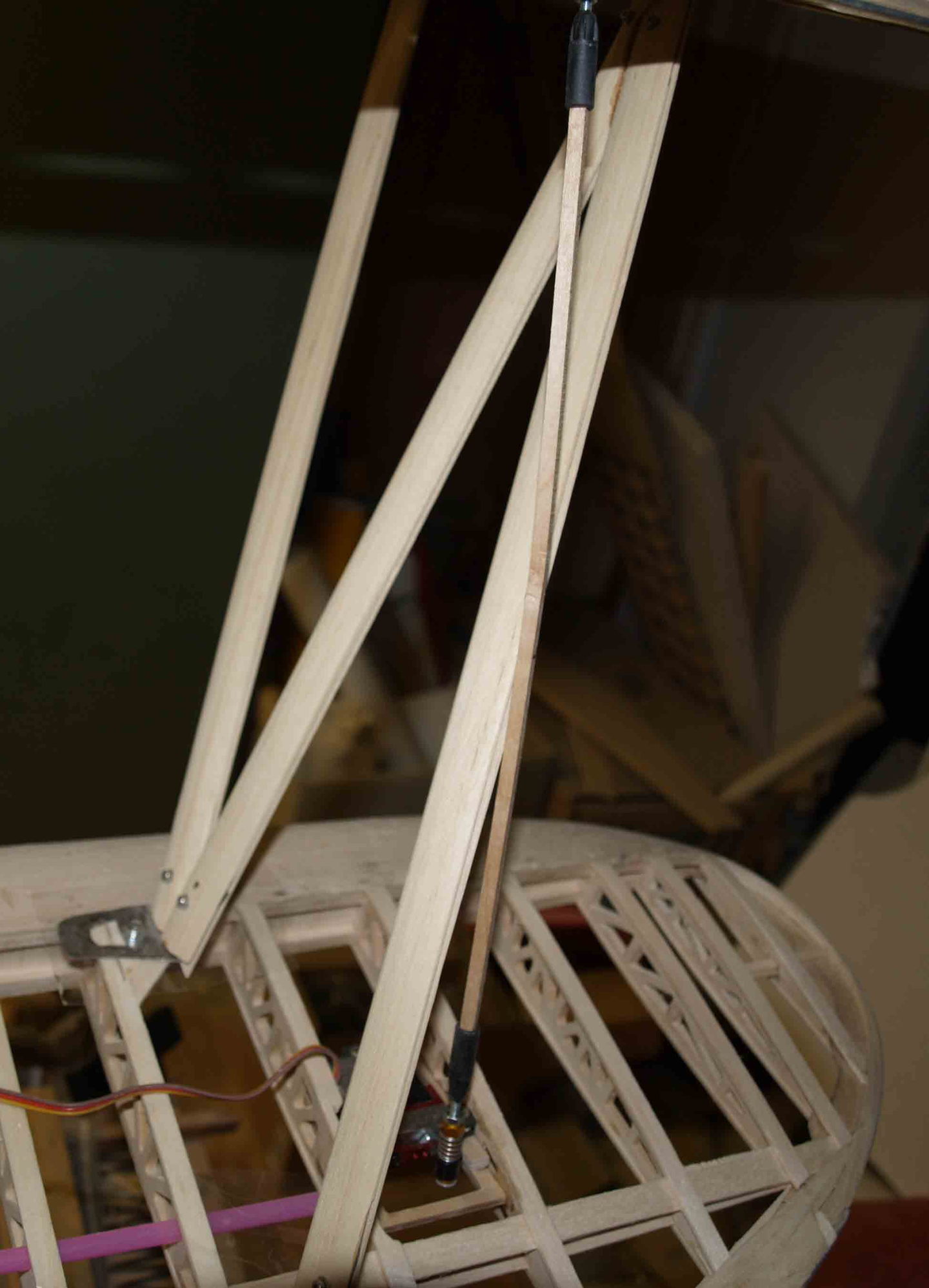
after replacing from this
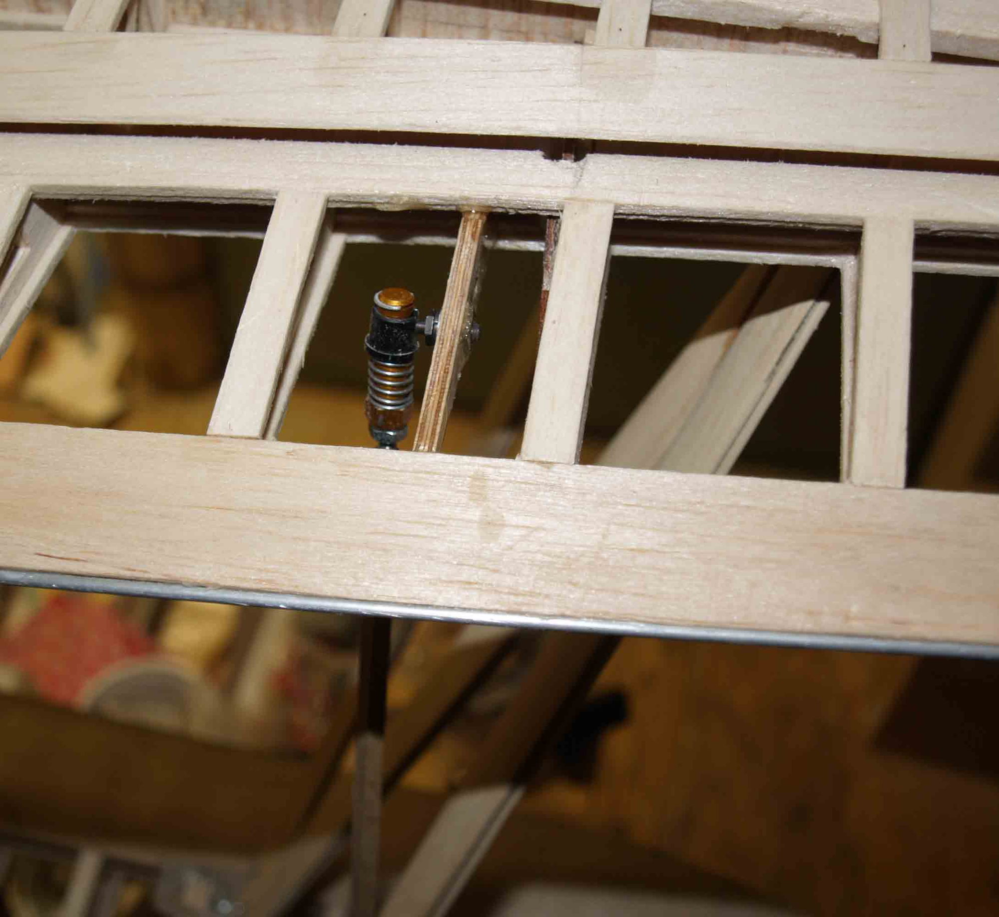
to this
it works as well, now it is enough space between the push rod and the strut.
@ warrenmiller > I only own an Opel Astra Sports Tourer, not the biggest car but it will be big enough. The longest part, the fuselage, is nit longer than 1700 mm, the wings are shorter than one meter. I have a princip > no more cylinder capacity than 60 cm� and no bigger car for models than a "normal" combi.
So, the building continued.
As next, I had to build the pushrods for the"Flettner"-flaps at the elevator.
I took some brass tube and cutted a small slit in it.
the push rod is made from carbon fiber
and so it works
Now to the wing struts. The objective target was to make them quick removable and that the flying wires should be easy to handle too.
I started with the basic points, made from 4 mm plywood with nuts inside
glued in place into the lower wing
and the upper wing
the next ste was to do some metal work, the fittings that hold the struts in place and also pick up the flying wires.
with some small strip I found out the right length for the struts.
the real struts are made from profiled abachi strips
I`ve done a mistake when I glued the upper linkage for the aileron push rod, it doesnt work free (it was to close to the wing strut)
after replacing from this
to this
it works as well, now it is enough space between the push rod and the strut.
Last edited by thomasmuckus; 01-05-2020 at 01:40 PM.
09-19-2020, 08:22 AM
#82
Thread Starter
Join Date: Jan 2014
Location: Eppendorf, Saxonia, Germany
Posts: 129
Likes: 0
Received 7 Likes
on
7 Posts
Hi guys,
I'm a little ashamed of the long break. I hope you can forgive me. Ther ara many reasons, motivation problems, I was sick for a time and so on. My doctor said, take it as therapeutic modeling and so I did.
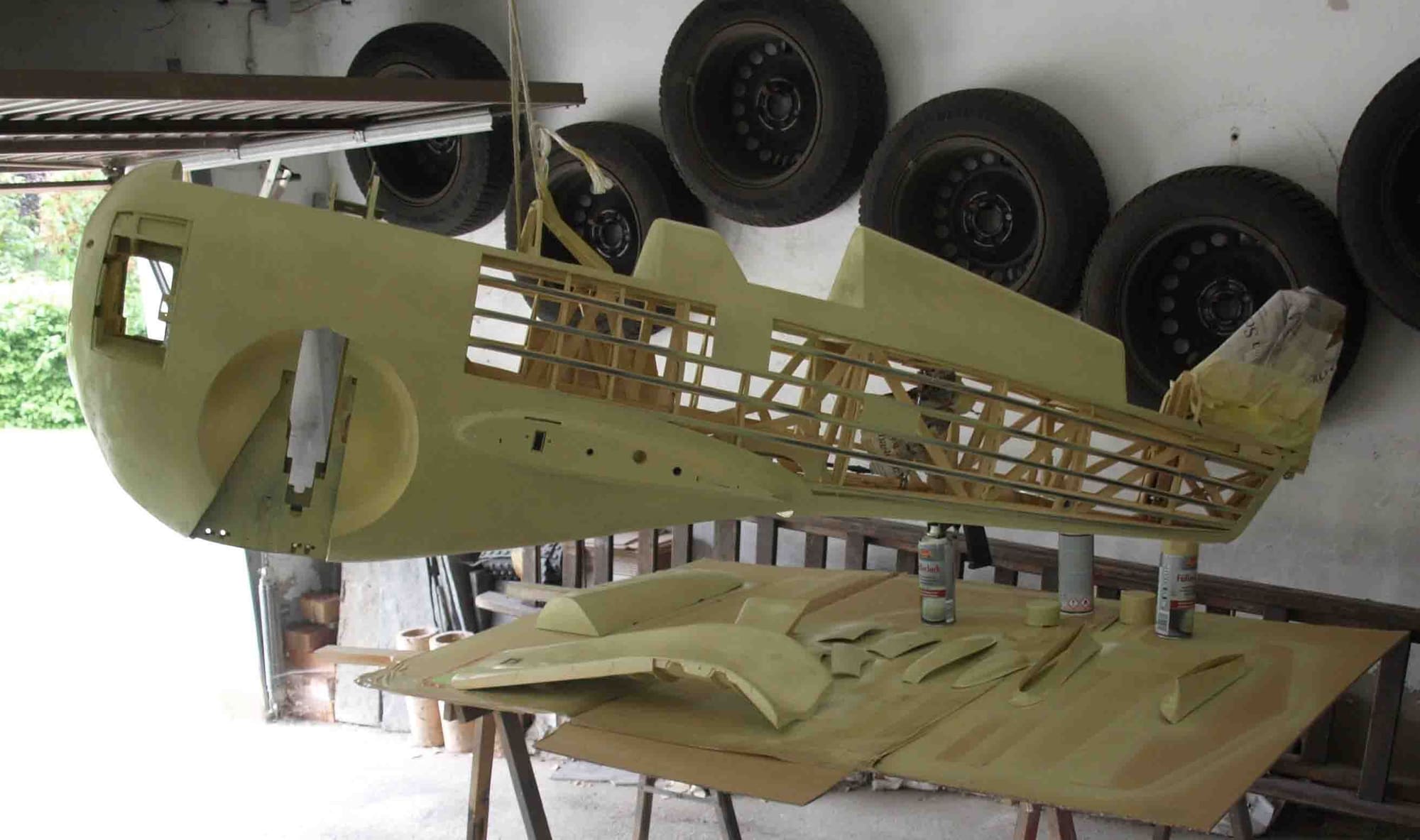
To improve my skills in spray painting I builded quickly this:
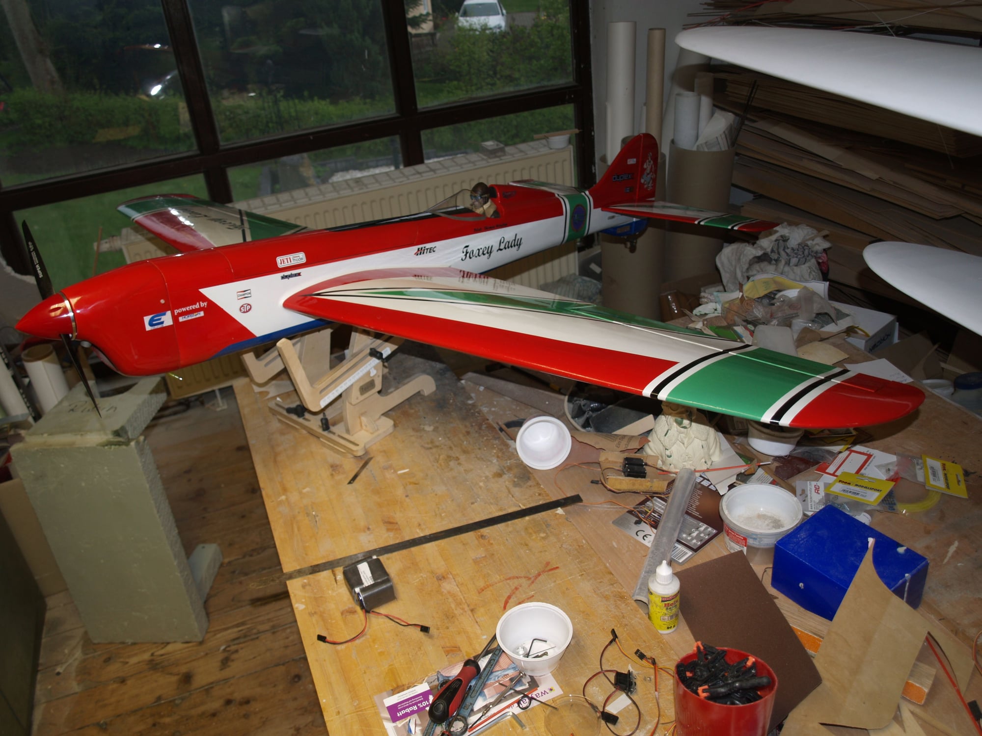
Not only to learn better working with the spray gun, I tried to test some kind of decals. We have a little advertising agency/copy shop in our village and the girl there had done a great job. The task was this:
She done a water sliding decal. My idea was, if it works with such a very, very bright backgraund like this, it will work on the aircraft with this muted colors too.
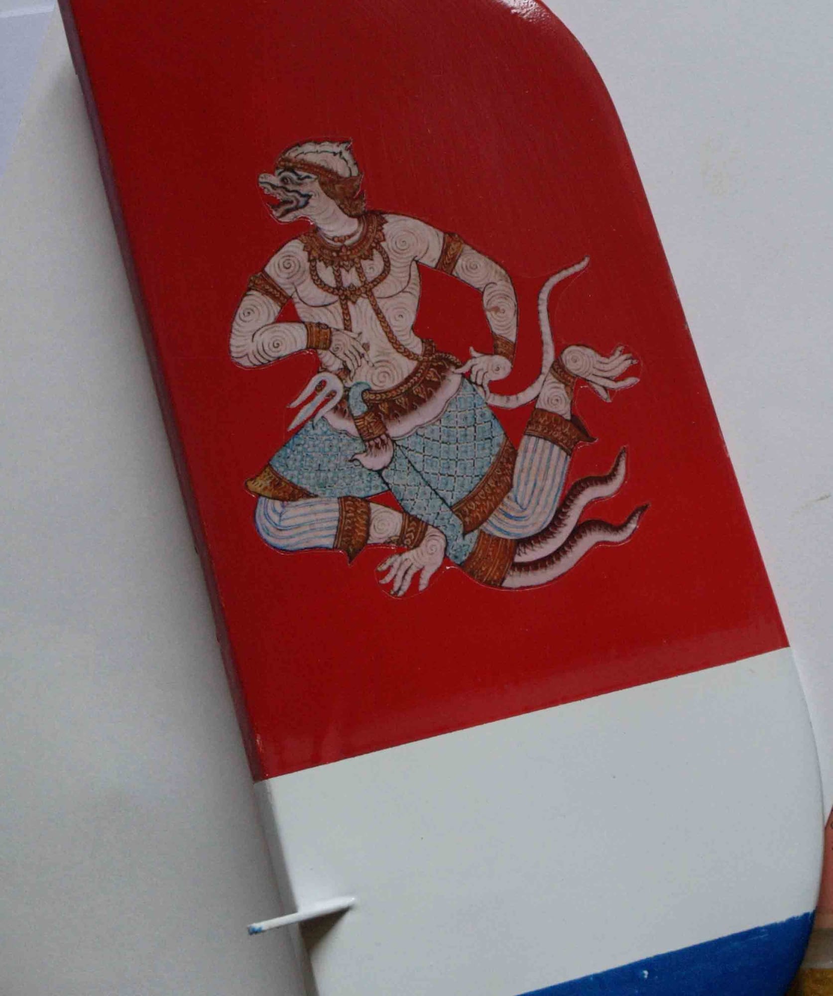
Looks nice doesn`t it?
I'm a little ashamed of the long break. I hope you can forgive me. Ther ara many reasons, motivation problems, I was sick for a time and so on. My doctor said, take it as therapeutic modeling and so I did.
To improve my skills in spray painting I builded quickly this:
Not only to learn better working with the spray gun, I tried to test some kind of decals. We have a little advertising agency/copy shop in our village and the girl there had done a great job. The task was this:
She done a water sliding decal. My idea was, if it works with such a very, very bright backgraund like this, it will work on the aircraft with this muted colors too.
Looks nice doesn`t it?
09-20-2020, 12:35 AM
#84
Thread Starter
Join Date: Jan 2014
Location: Eppendorf, Saxonia, Germany
Posts: 129
Likes: 0
Received 7 Likes
on
7 Posts
Thanks a lot, Mike,
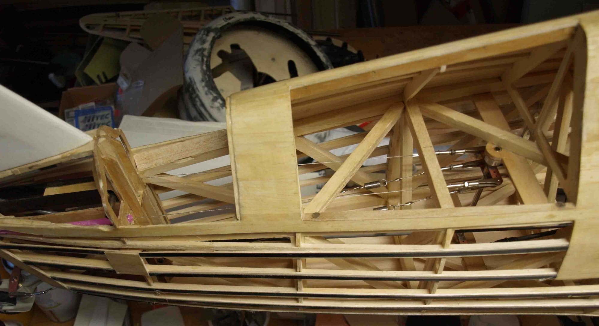
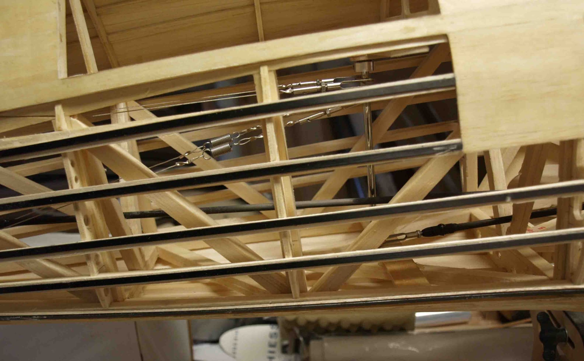
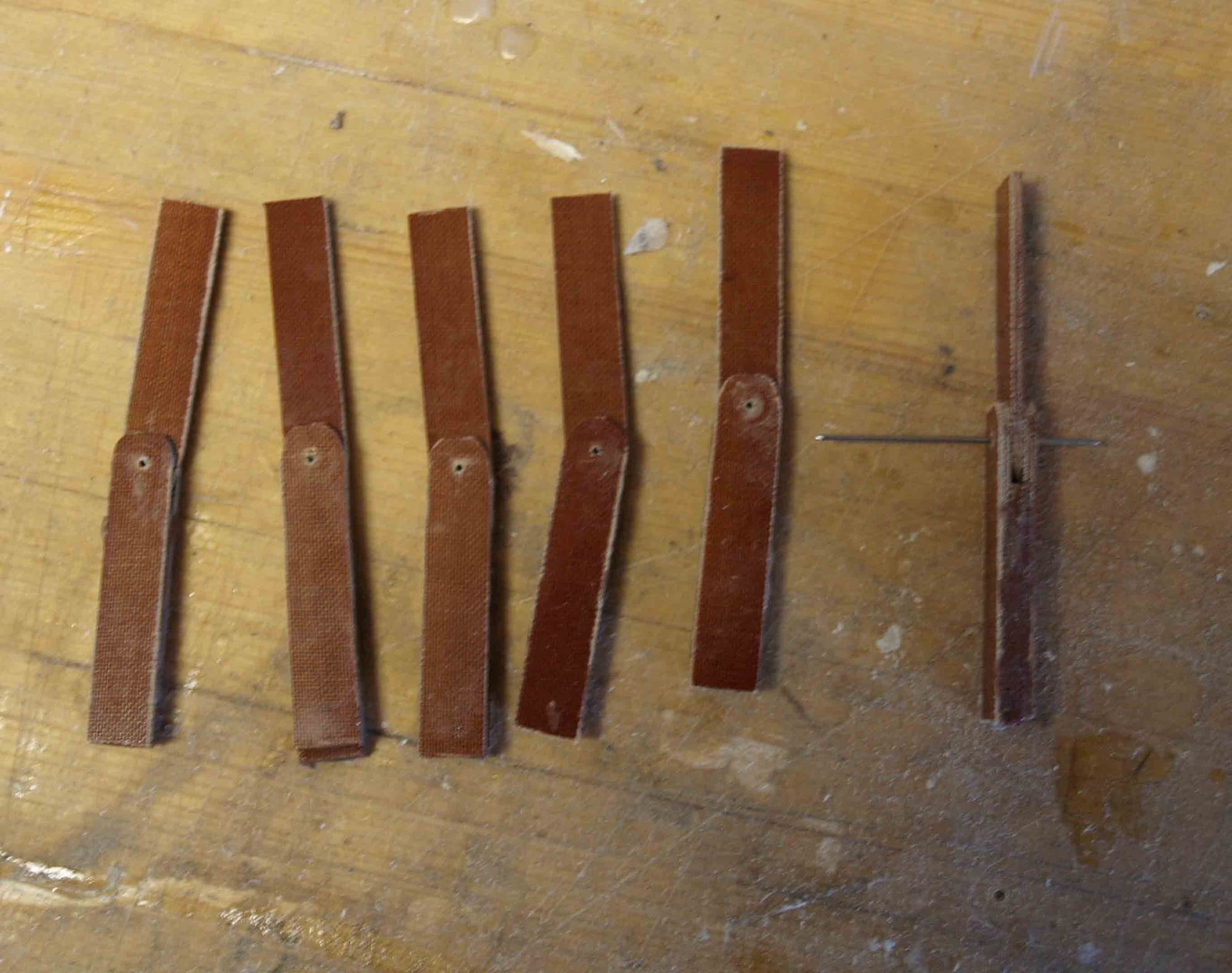
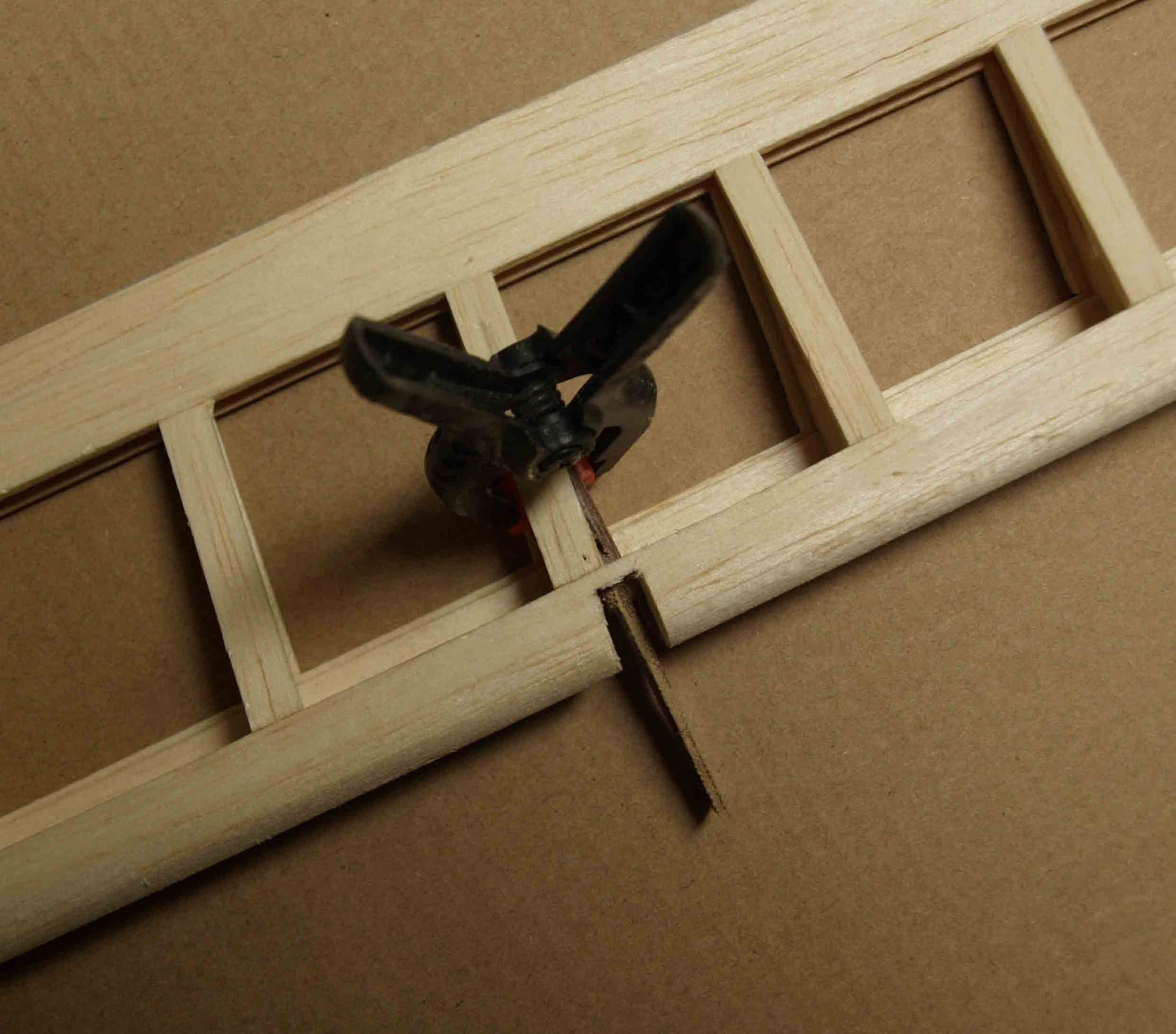
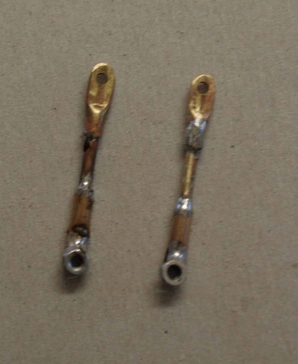
freshly motivated I started to rebuild the flying wires for the middle part of upper wing. The first attempt where simply wires with soldered fork heads. The problem was, after removing they lost tension. So I had to find a solution to rethigten after rebuilding. I found it on Mick Reeves site, the only thing, very expensive if you need so many like me. So I decided to make them my self. As flying wire I use small strips of stainless steel. A frieds son water cutted them from 0,5 mm stainless steel sheet, 2,5 mm wide. The beginning is very simple, I soldered a solder sleeve M2 at ons side. The other side is a little bit more tricky. With the late I made suitable a M2 screw head to a M2 fork head. The thread I drilled out.
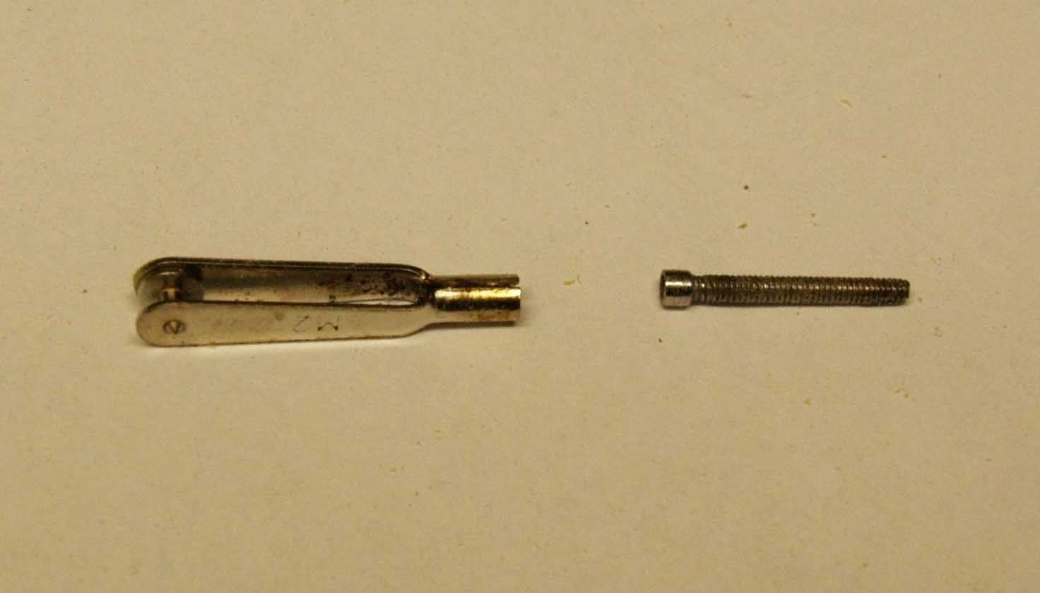
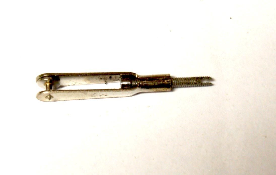
After cutting a small slot into the screw shaft I soldered the whole thing on the other side of the flying wire > done
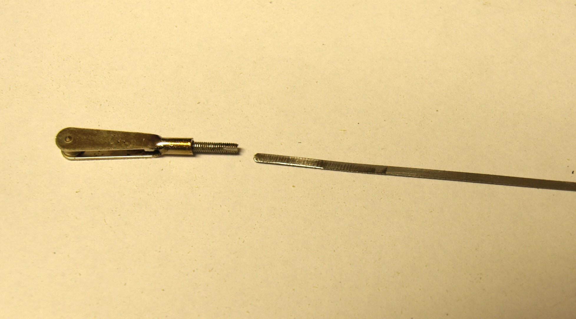
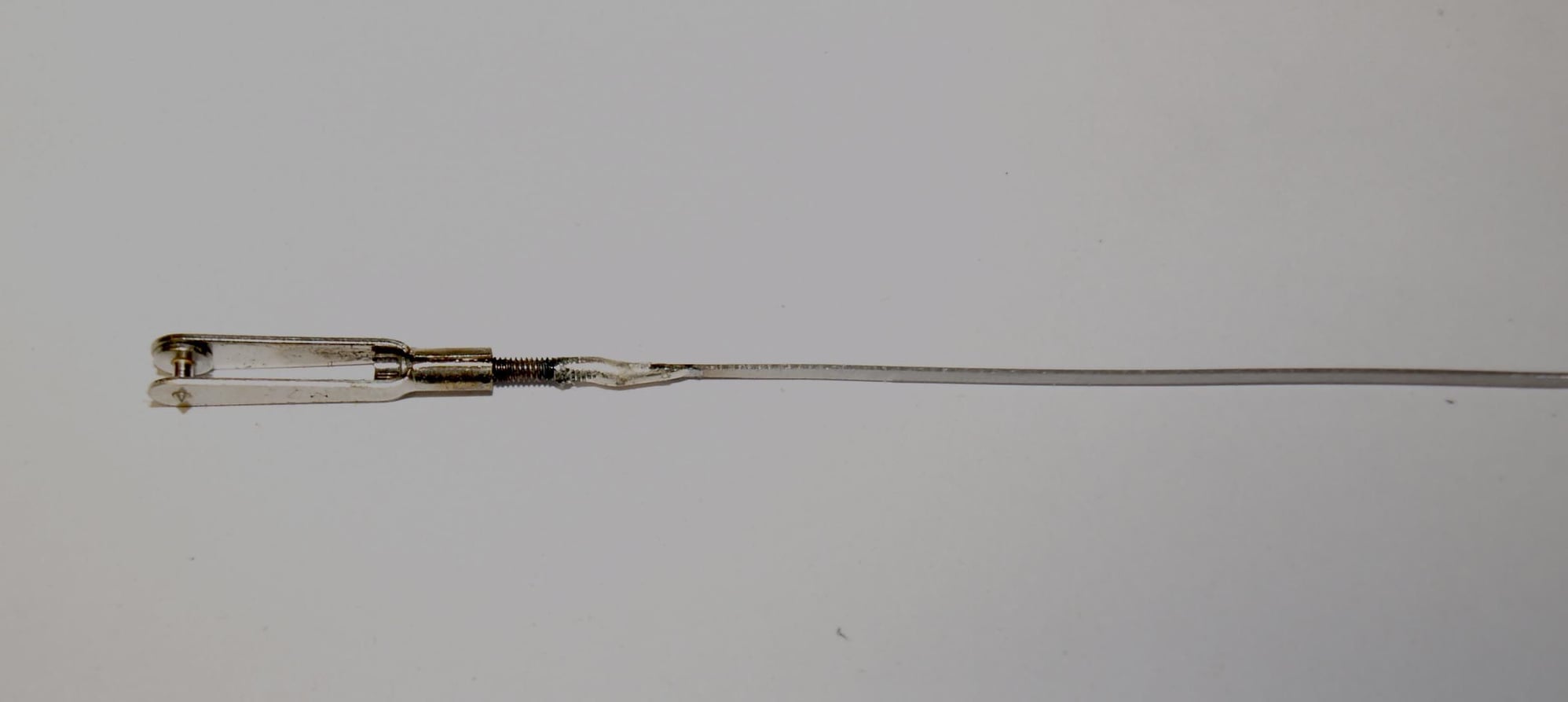
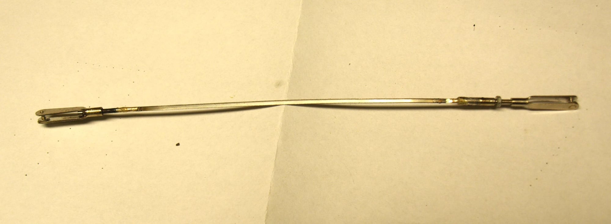
Now I can remove and rebuild the middle part without any problems.
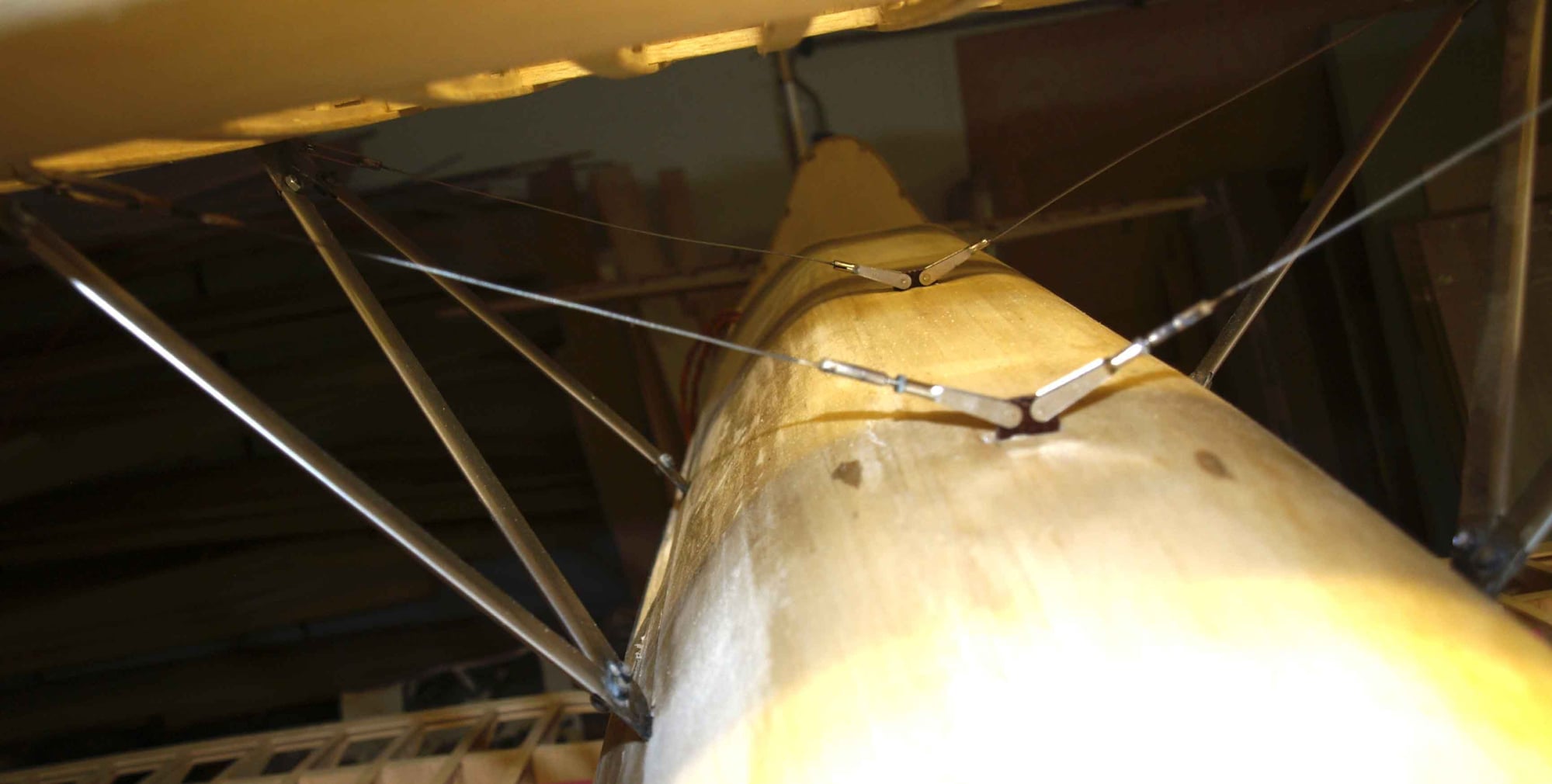
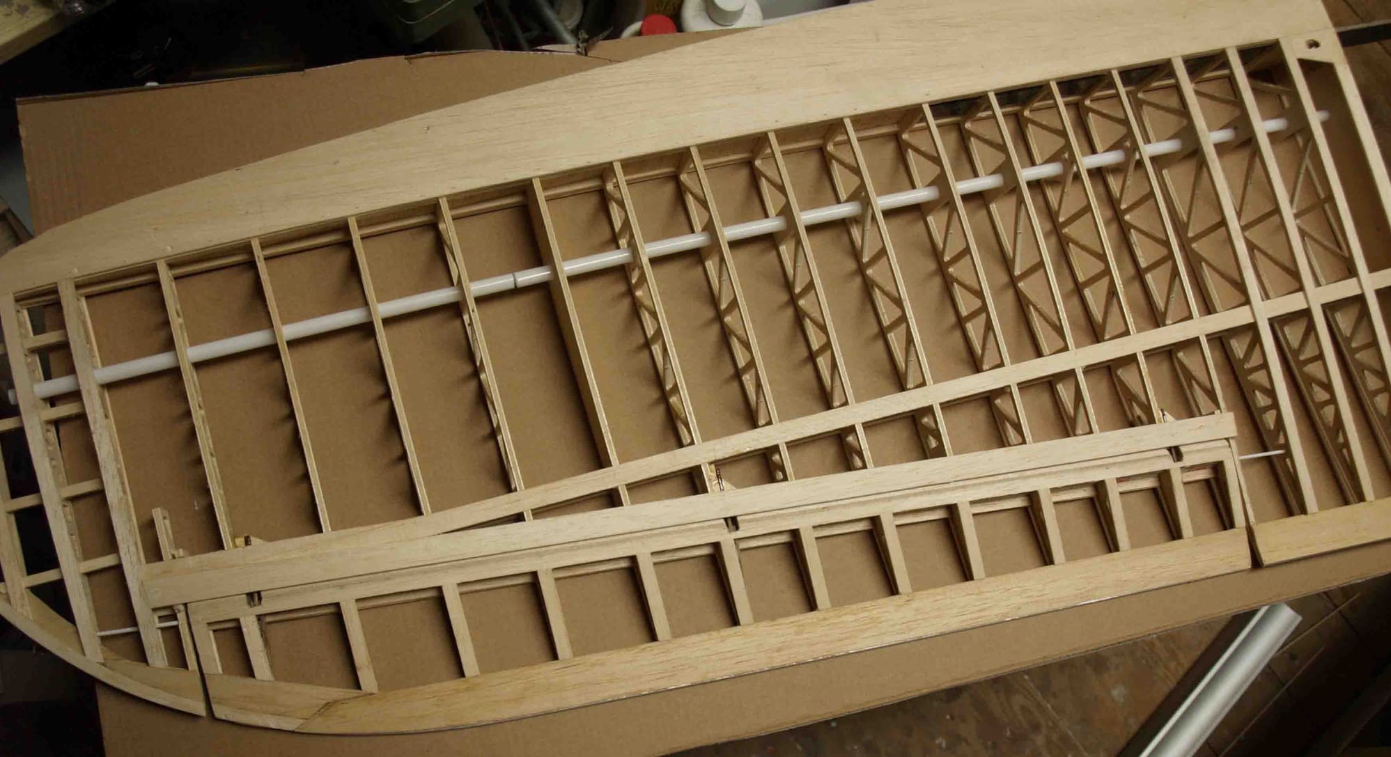
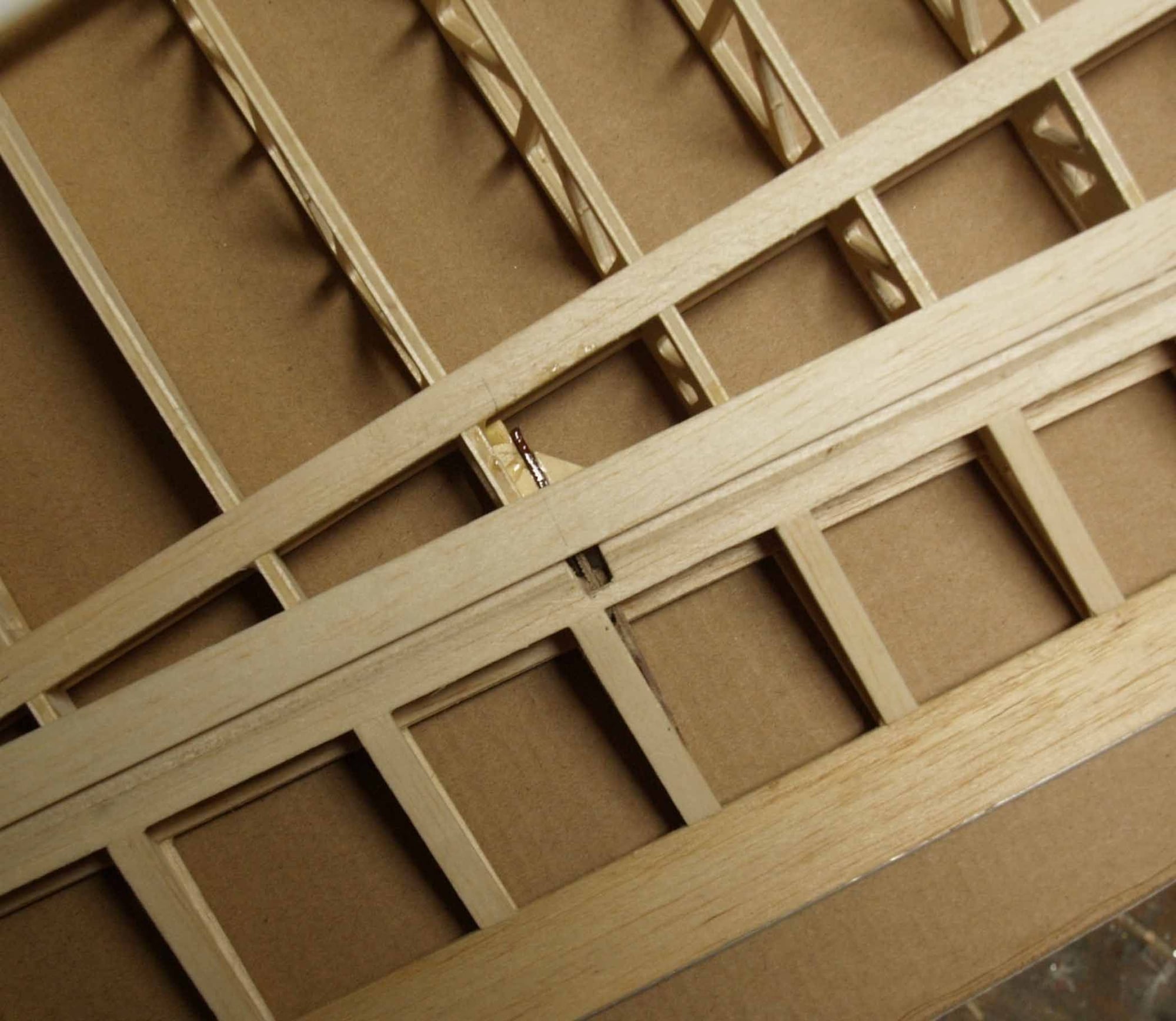
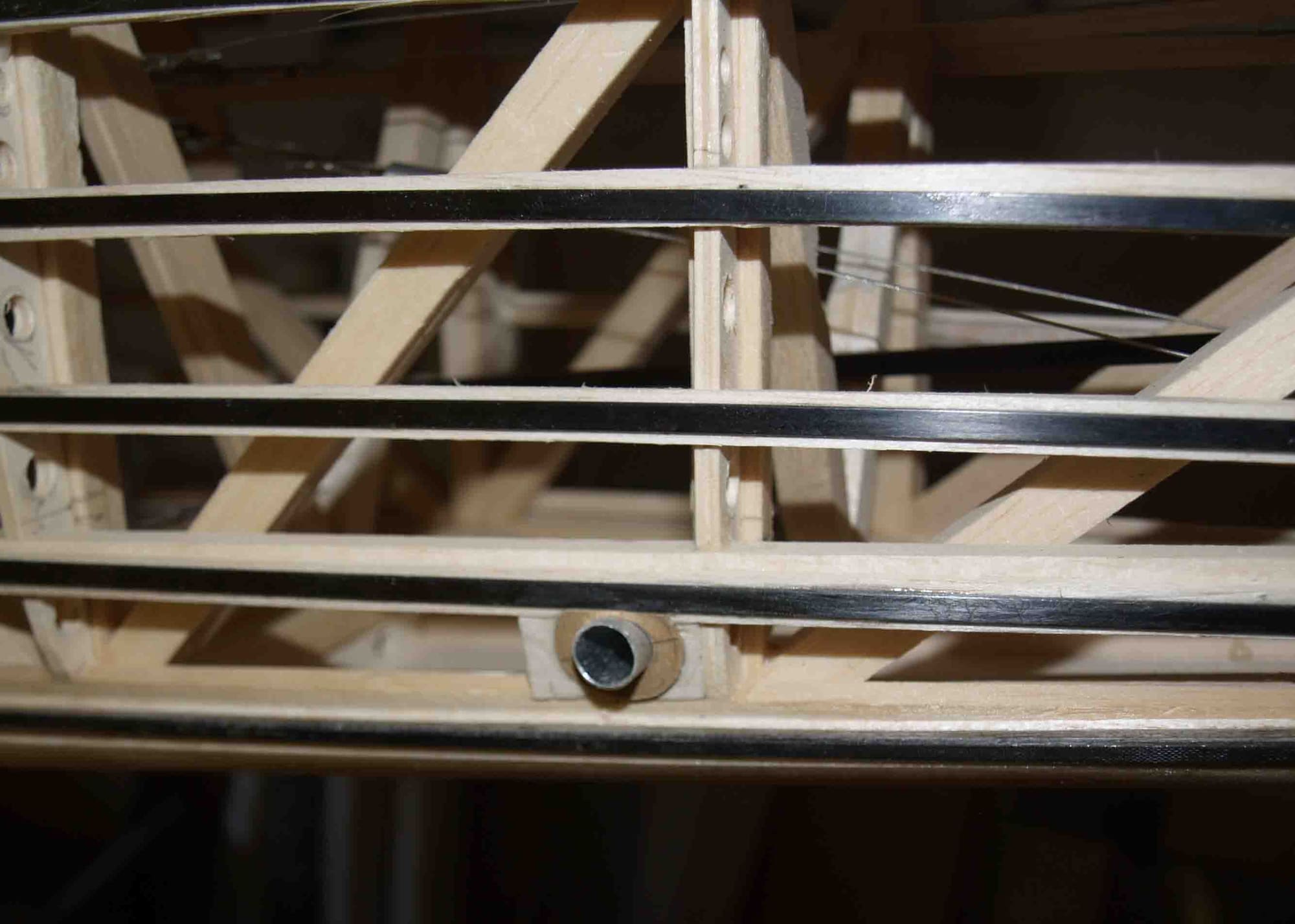
Before covering the wing I also had to build in the cables for the position lights. I use the wingstruts as a part of the electrical wiring system.
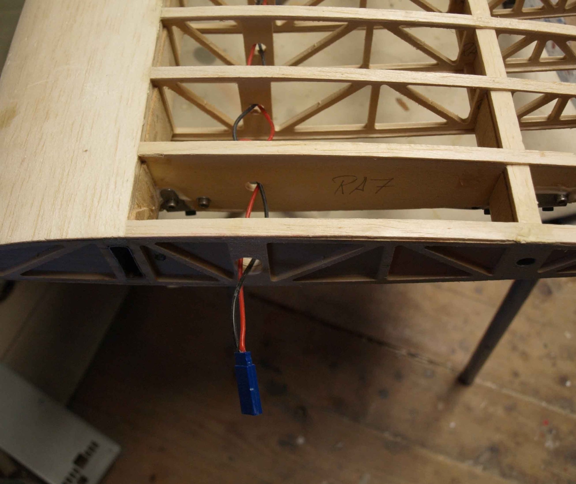
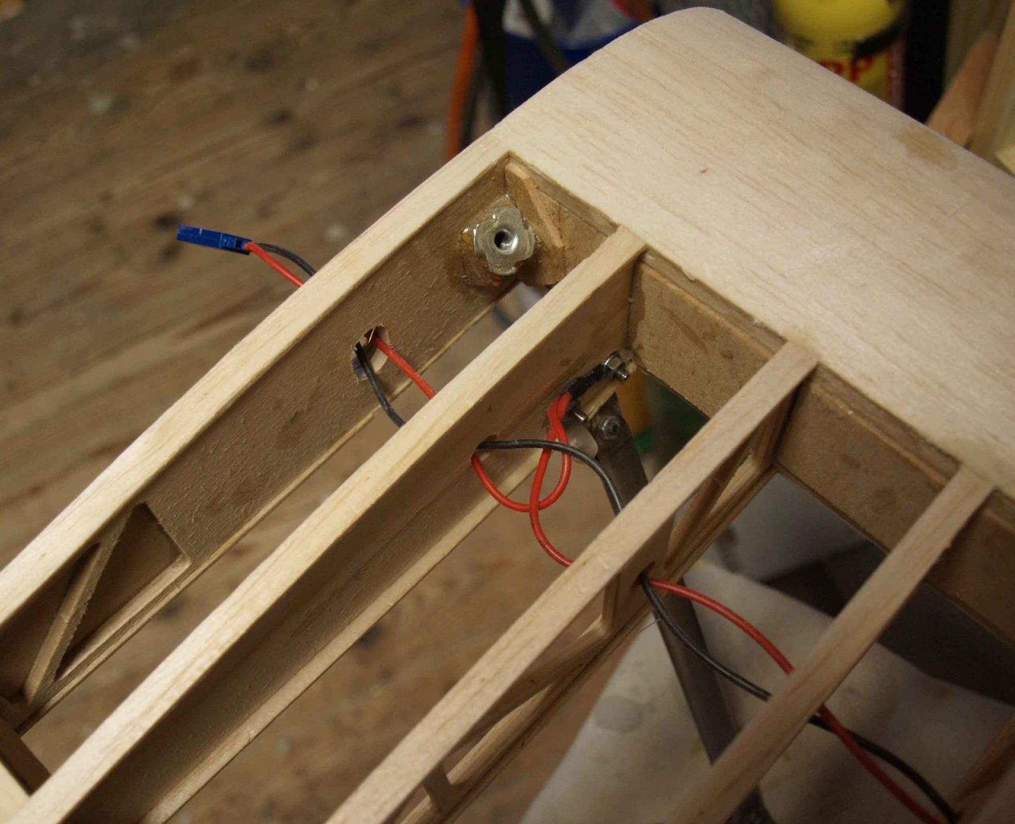
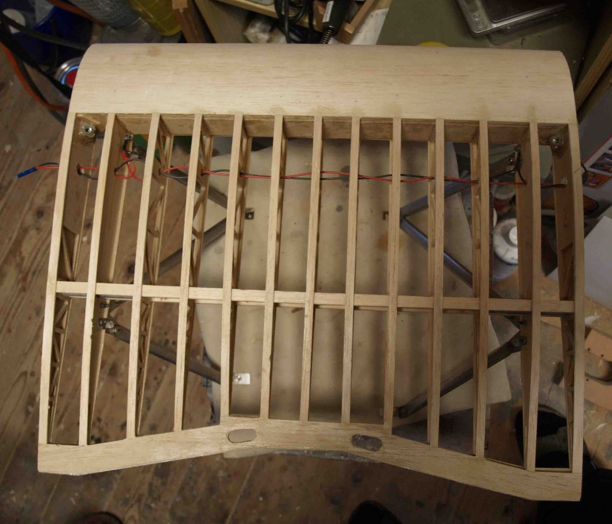
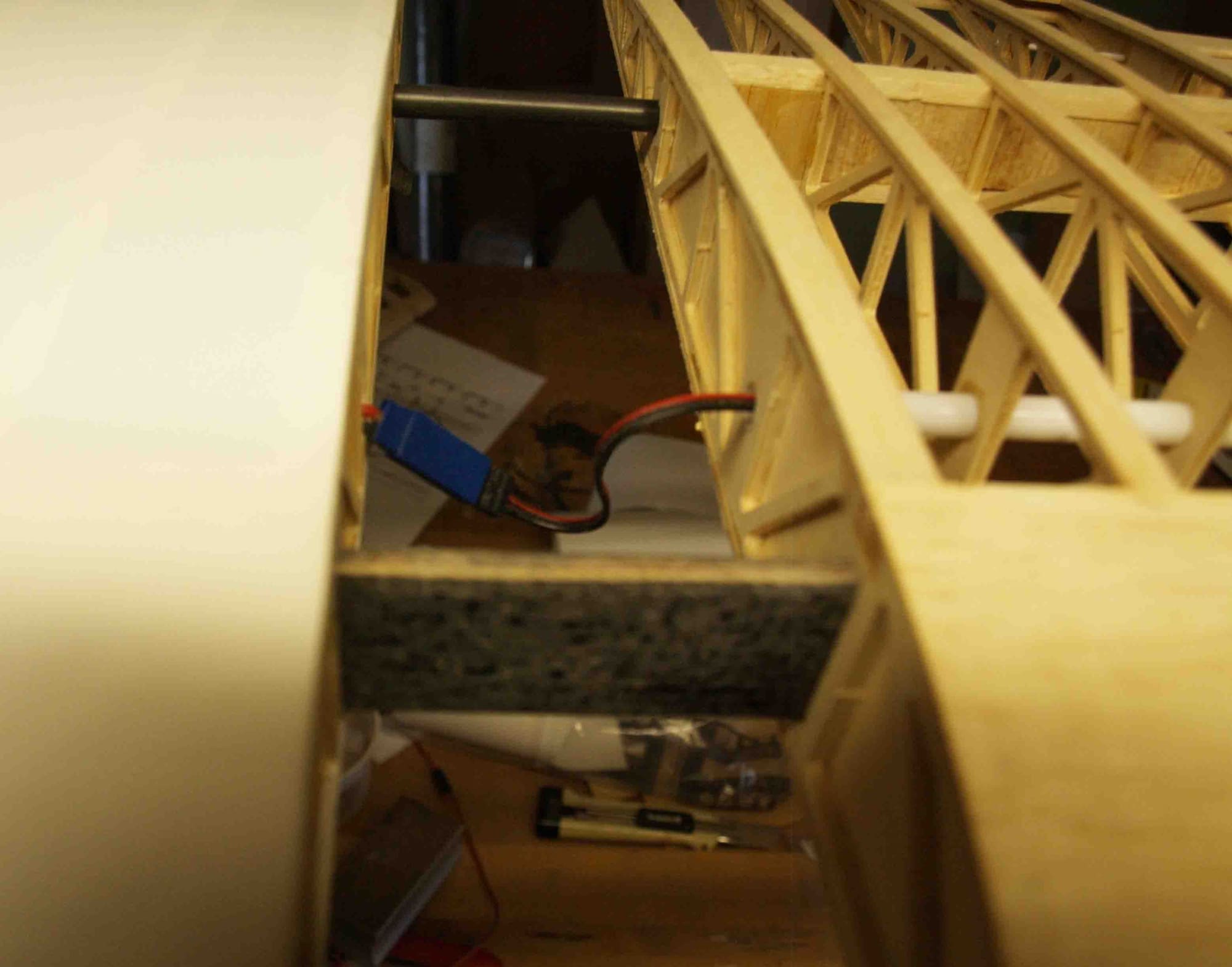
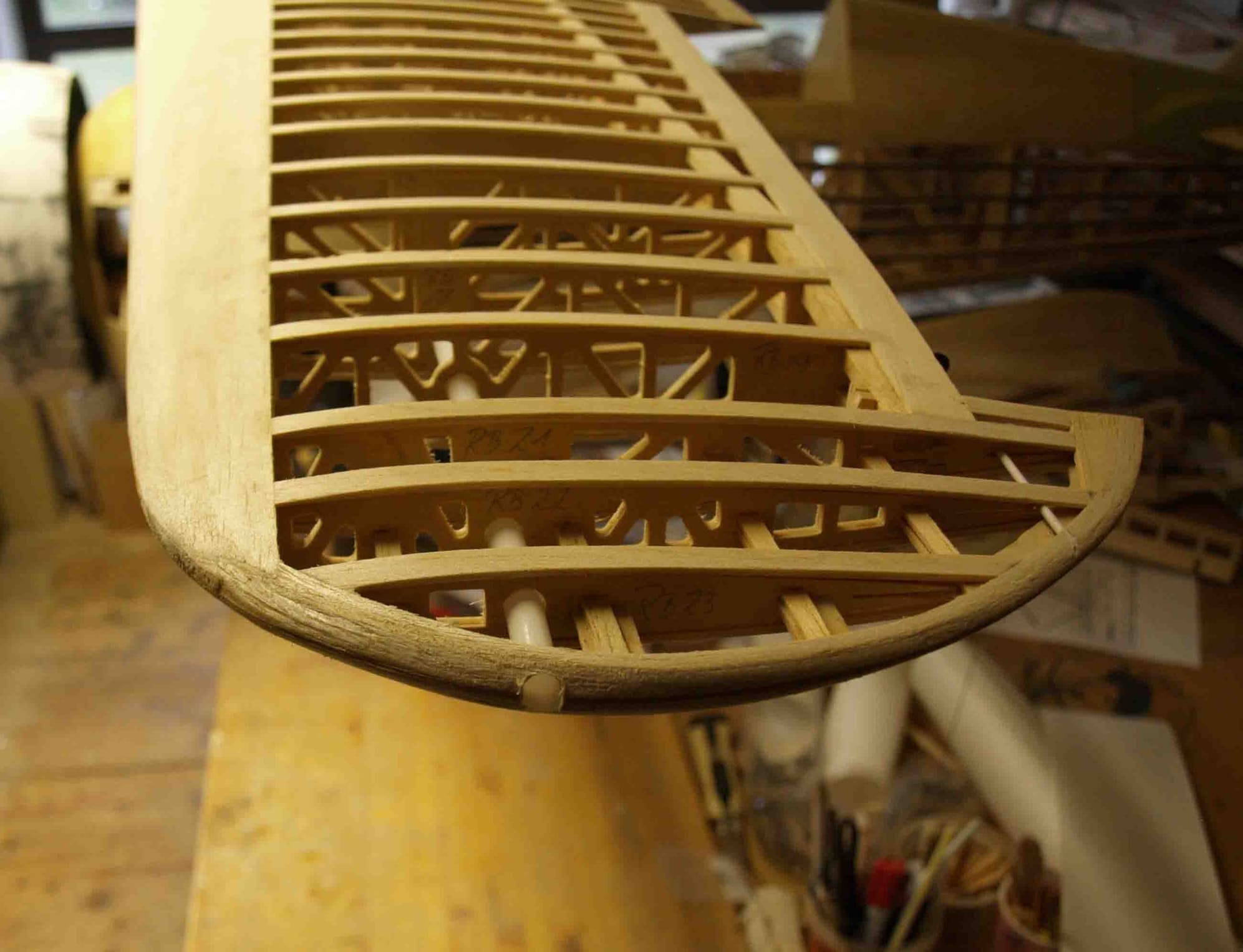
a big fat party drinking straw works as cable canal in the wings
I cutted handles into the wing tips of the upper wings,
cutted out the trim tab of the rudder,
installed the tube for leveling the hull

so it was prepared for covering
freshly motivated I started to rebuild the flying wires for the middle part of upper wing. The first attempt where simply wires with soldered fork heads. The problem was, after removing they lost tension. So I had to find a solution to rethigten after rebuilding. I found it on Mick Reeves site, the only thing, very expensive if you need so many like me. So I decided to make them my self. As flying wire I use small strips of stainless steel. A frieds son water cutted them from 0,5 mm stainless steel sheet, 2,5 mm wide. The beginning is very simple, I soldered a solder sleeve M2 at ons side. The other side is a little bit more tricky. With the late I made suitable a M2 screw head to a M2 fork head. The thread I drilled out.
After cutting a small slot into the screw shaft I soldered the whole thing on the other side of the flying wire > done
Now I can remove and rebuild the middle part without any problems.
Before covering the wing I also had to build in the cables for the position lights. I use the wingstruts as a part of the electrical wiring system.
a big fat party drinking straw works as cable canal in the wings
I cutted handles into the wing tips of the upper wings,
cutted out the trim tab of the rudder,
installed the tube for leveling the hull
so it was prepared for covering
Last edited by thomasmuckus; 09-20-2020 at 12:48 AM.
09-20-2020, 01:02 AM
#85
Thread Starter
Join Date: Jan 2014
Location: Eppendorf, Saxonia, Germany
Posts: 129
Likes: 0
Received 7 Likes
on
7 Posts
By the way, I needed some houses for the deflection levers into the upper wings
a wooden model, a small tool and they were deep drawn from thin ABS
the trim tab of the rudder was quick done
Now I was able to cover with oratex.
Looks close like a real aircraft
a wooden model, a small tool and they were deep drawn from thin ABS
the trim tab of the rudder was quick done
Now I was able to cover with oratex.
Looks close like a real aircraft
The following users liked this post:
mgnostic (09-20-2020)
09-21-2020, 02:30 AM
#87
Thread Starter
Join Date: Jan 2014
Location: Eppendorf, Saxonia, Germany
Posts: 129
Likes: 0
Received 7 Likes
on
7 Posts
Me too my friend, me too but it`s a long, long way .... I can see the light at the end of the tunnel
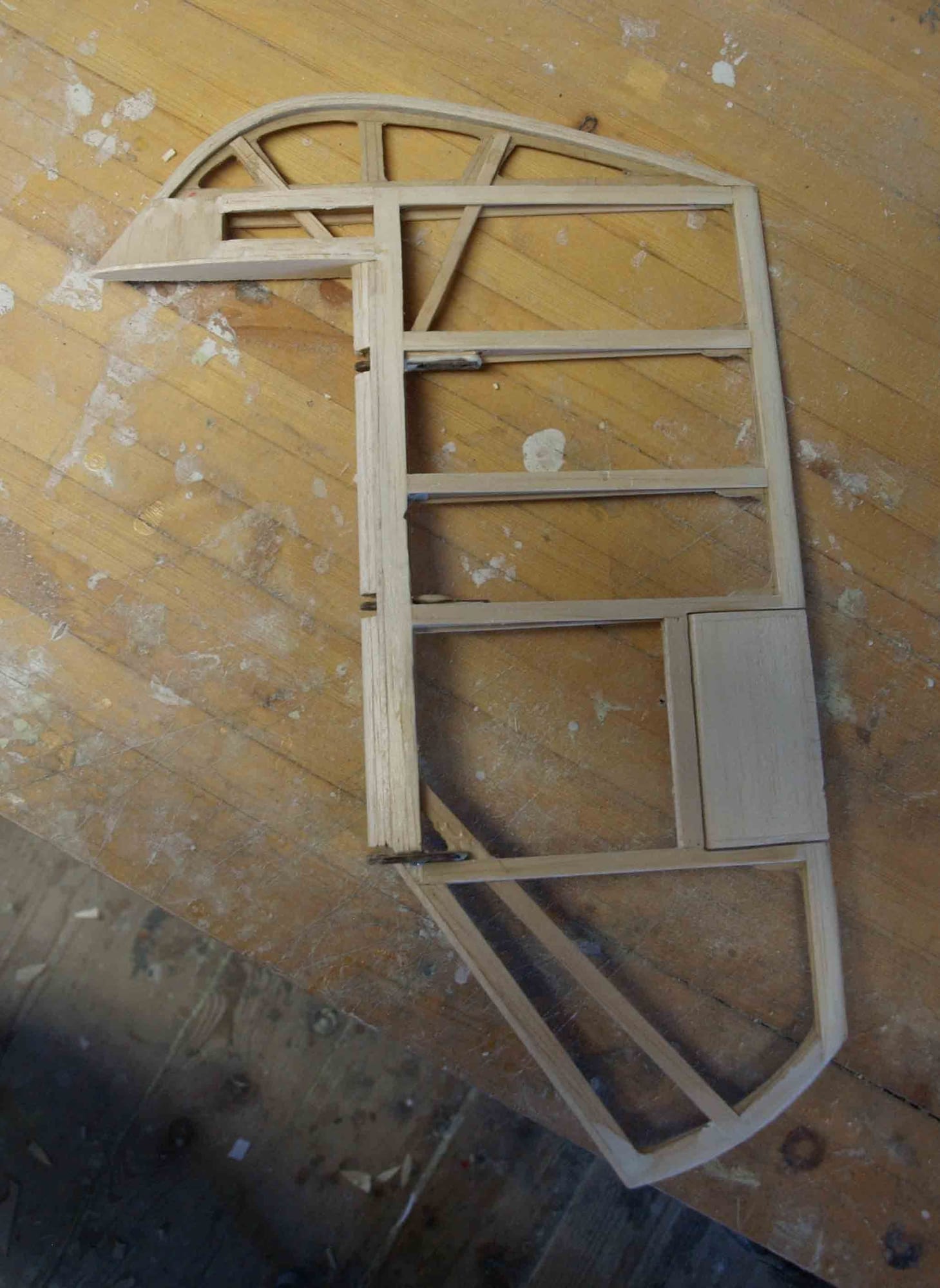
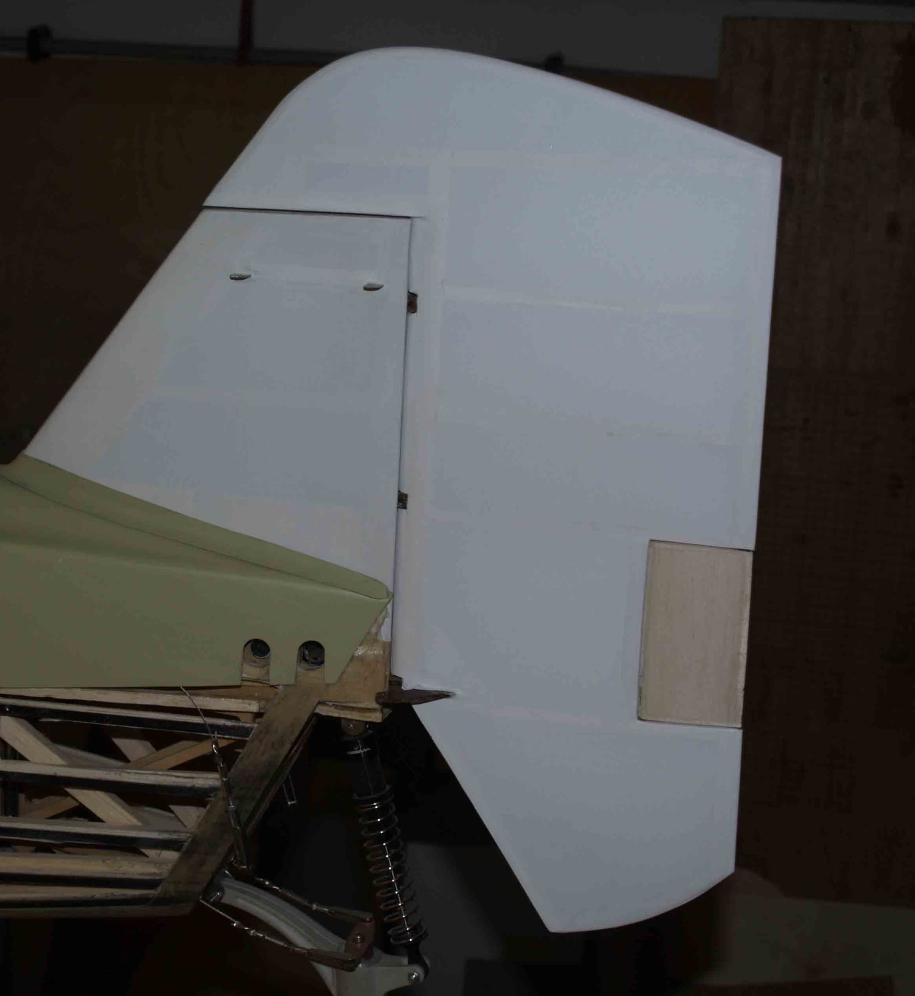
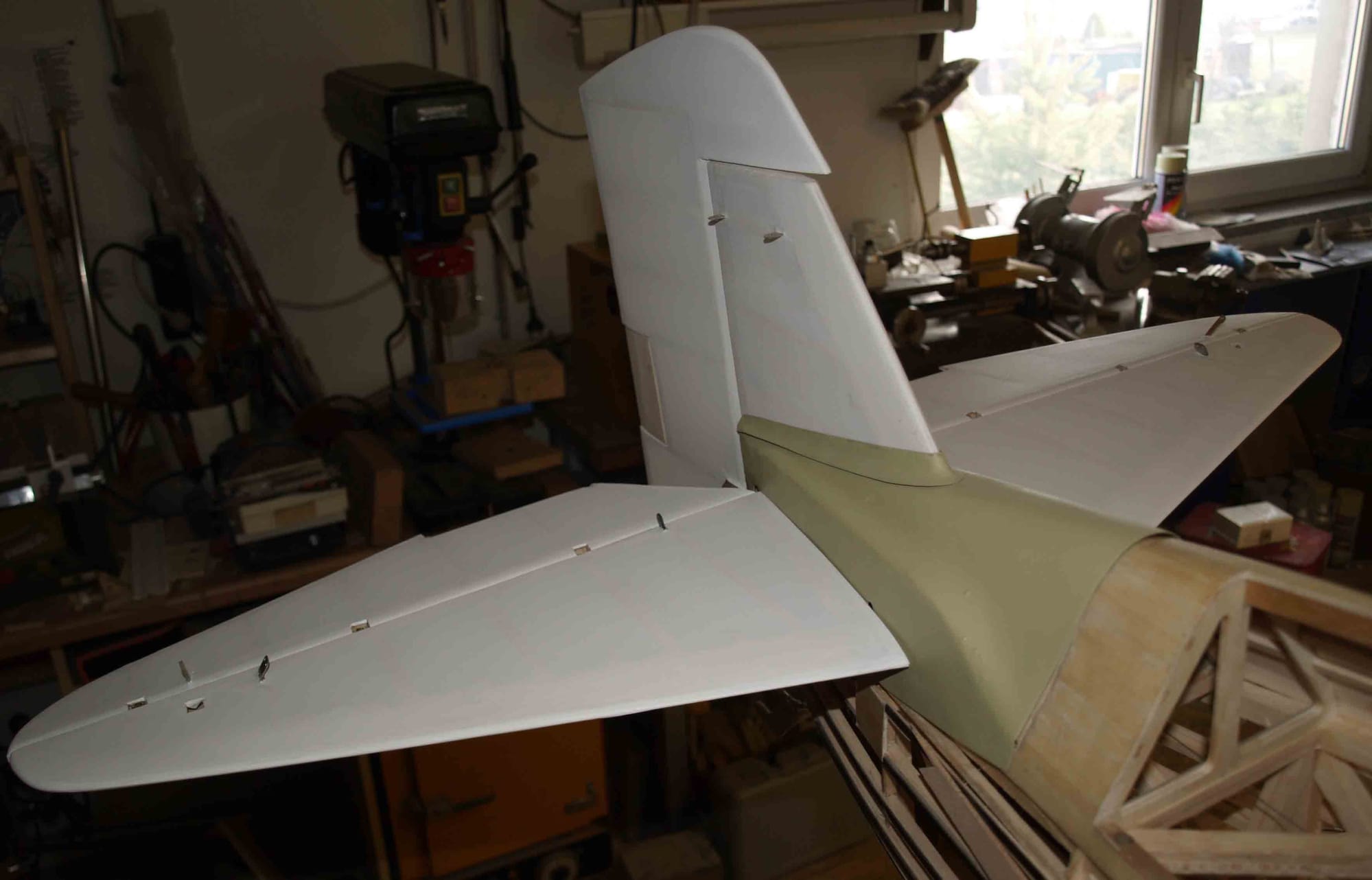
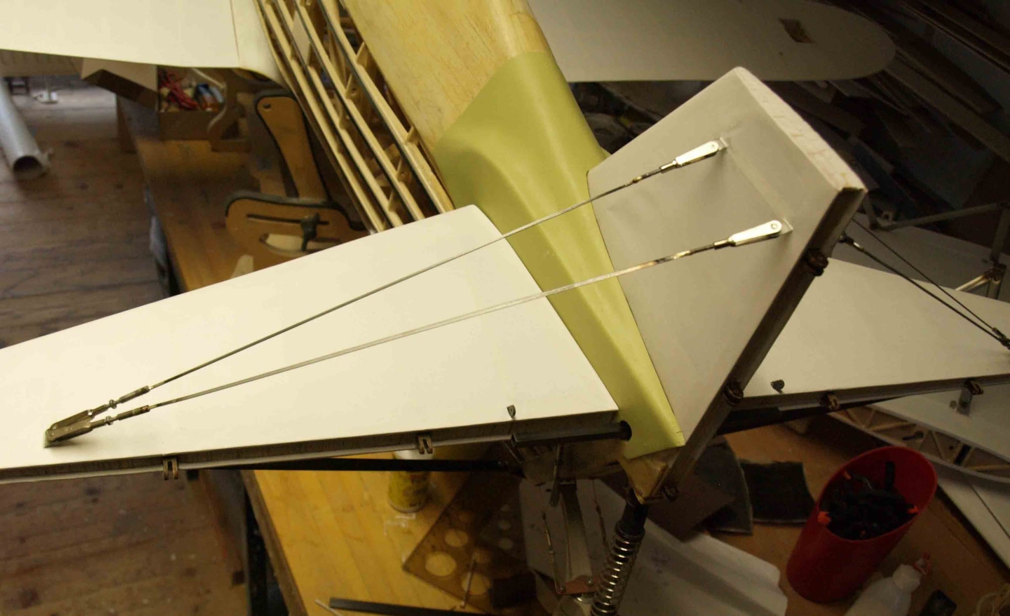
Now to the tail. The lower side is supported by a strut. I`ve done it with a carbon fiber strip, 1 mm x 8 mm. The fitting I`ve made of stainless steel and solded a M3 nut
The counterpart on the fuselgae is also done of stainless steel (0,5 mm)
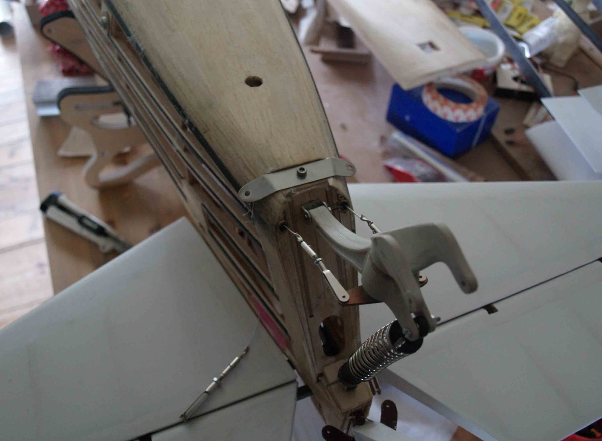
The first time I worked with a cross laser, cool.....
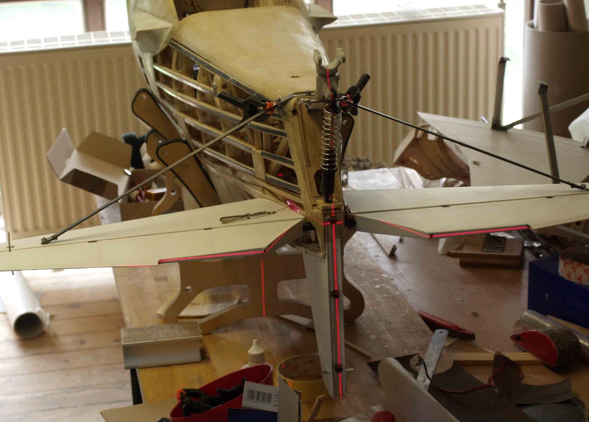
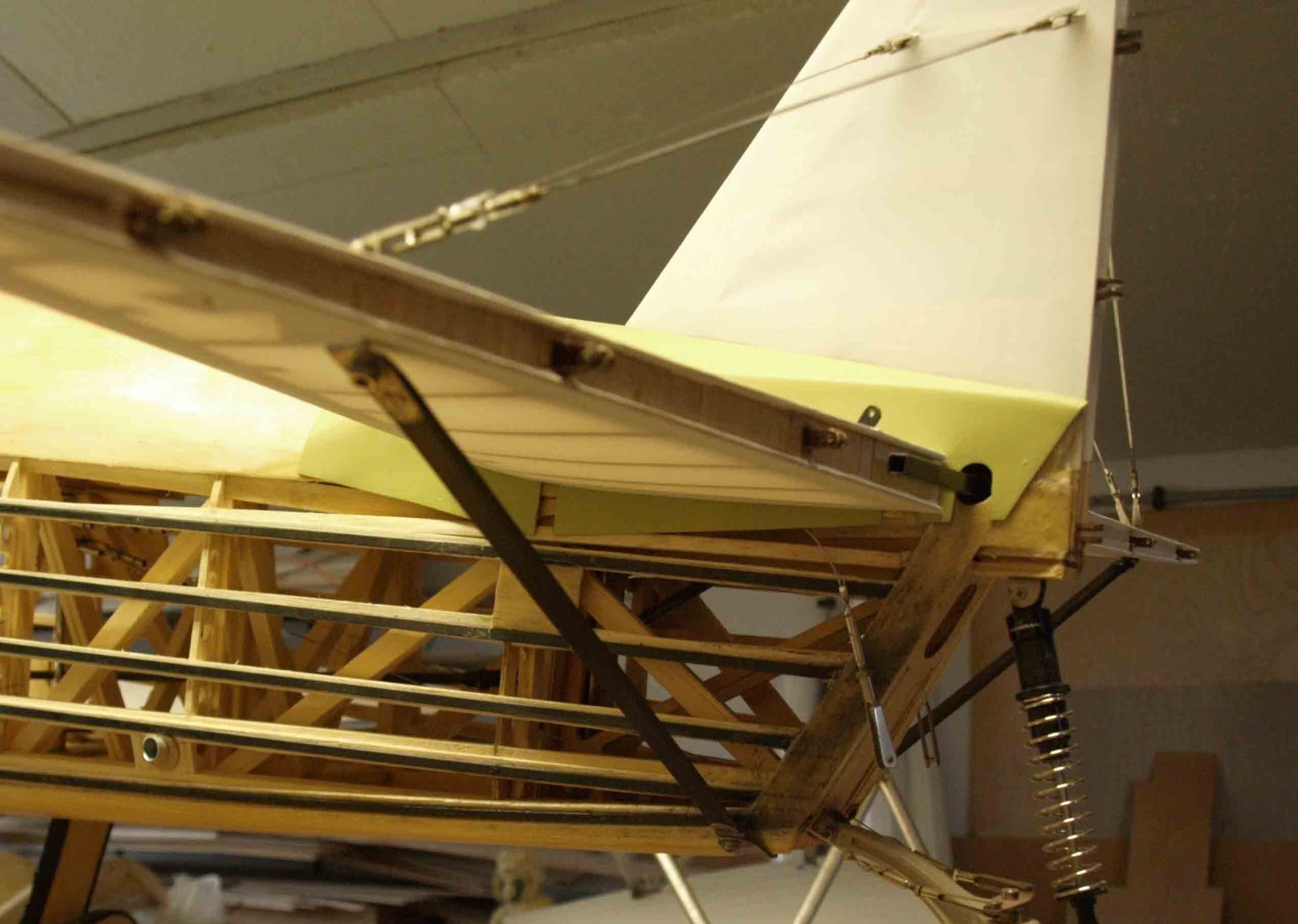
On the upper side are nomal flying wires. I made them exactly like the others, not a real problem.
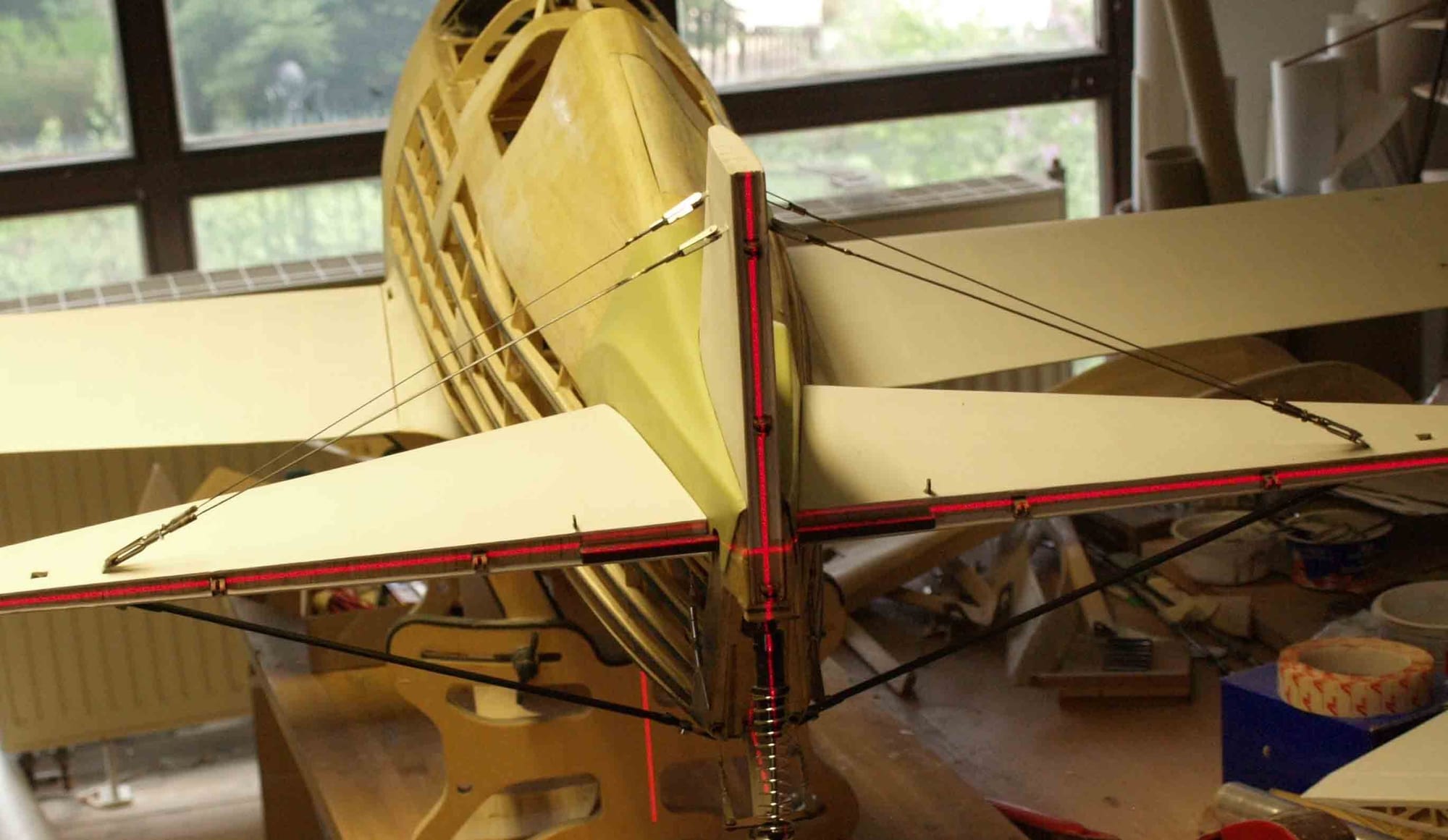
cross laser again
but it`s a long, long way.... I can see the light at the end of the tunnelNow to the tail. The lower side is supported by a strut. I`ve done it with a carbon fiber strip, 1 mm x 8 mm. The fitting I`ve made of stainless steel and solded a M3 nut
The counterpart on the fuselgae is also done of stainless steel (0,5 mm)
The first time I worked with a cross laser, cool.....
On the upper side are nomal flying wires. I made them exactly like the others, not a real problem.
cross laser again
Last edited by thomasmuckus; 09-21-2020 at 02:32 AM.
09-21-2020, 03:29 AM
#88
Thread Starter
Join Date: Jan 2014
Location: Eppendorf, Saxonia, Germany
Posts: 129
Likes: 0
Received 7 Likes
on
7 Posts
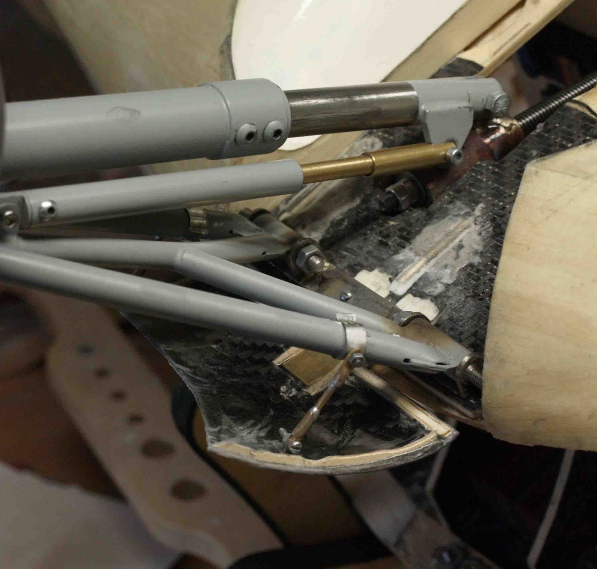
The next step was to build and install the landing gear doors.
At first, I cutted some foam in form and sanded it.
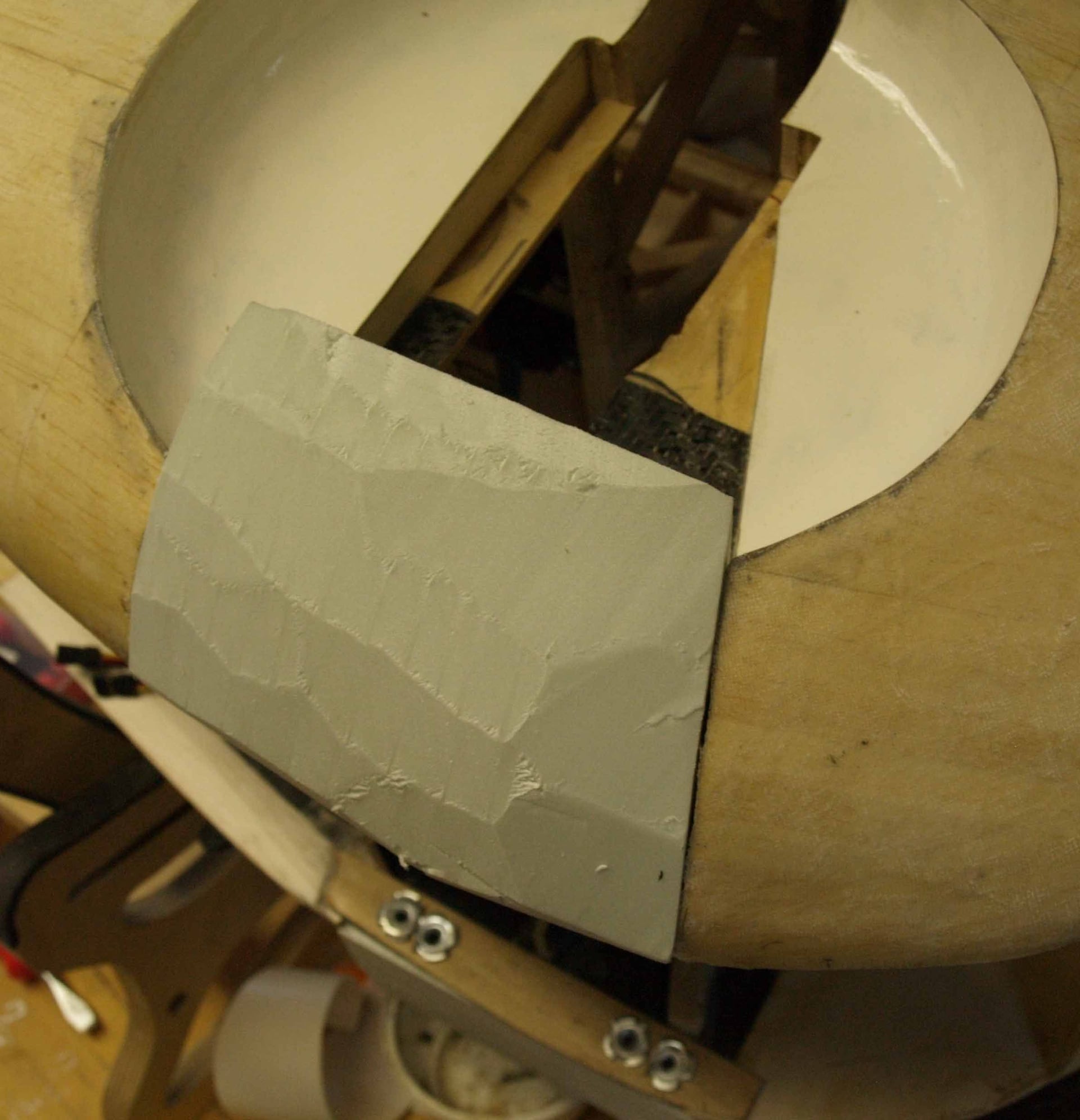
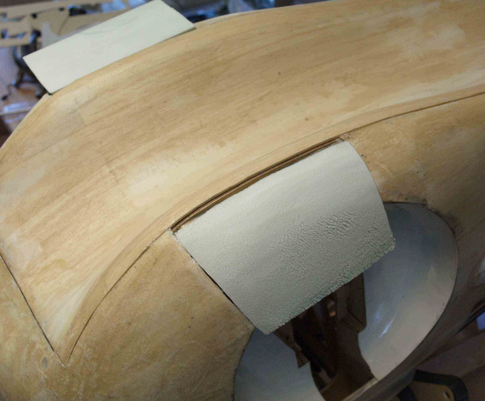
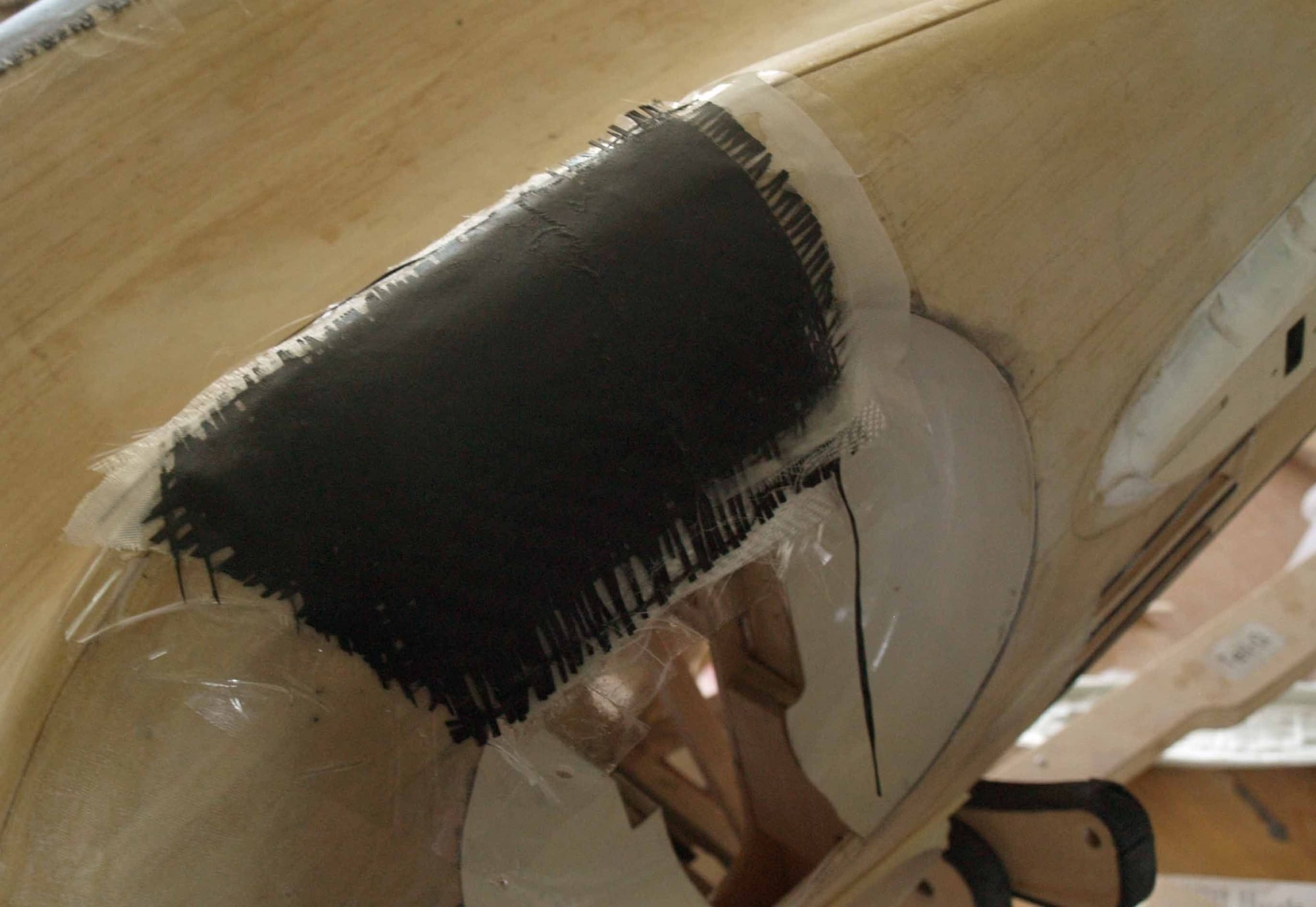
the door itself was made of glass and carbon fiber, laminated direct on the fuselage/foam.
after cutting in shape I glued some wooden reinforcements in place
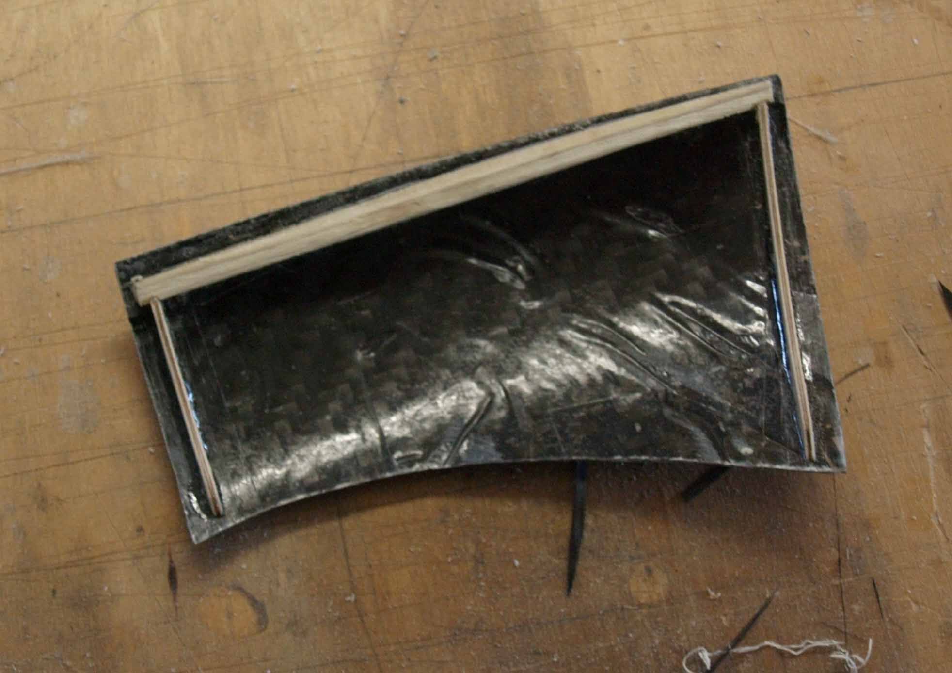
it fits quite well
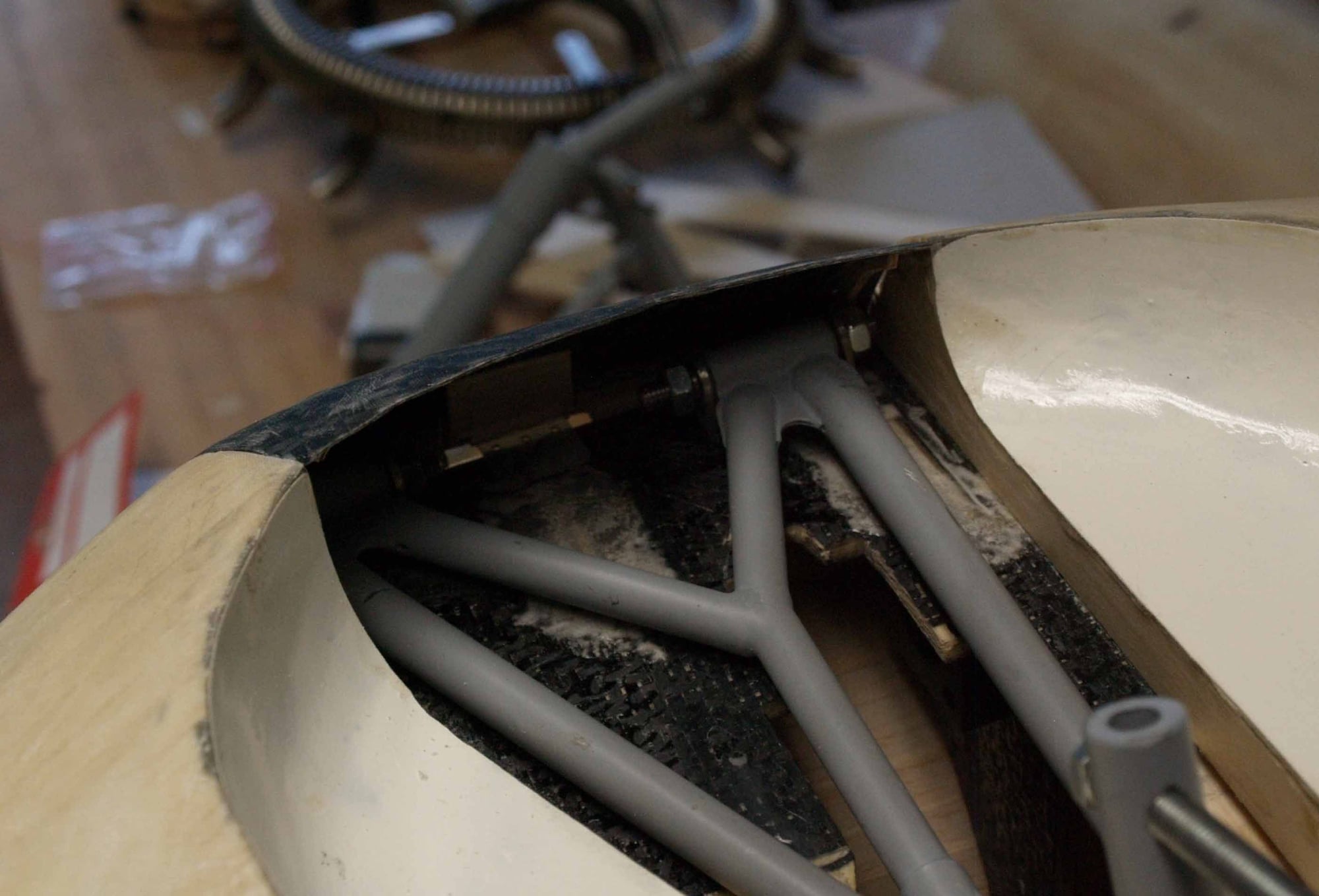
some struts of brass
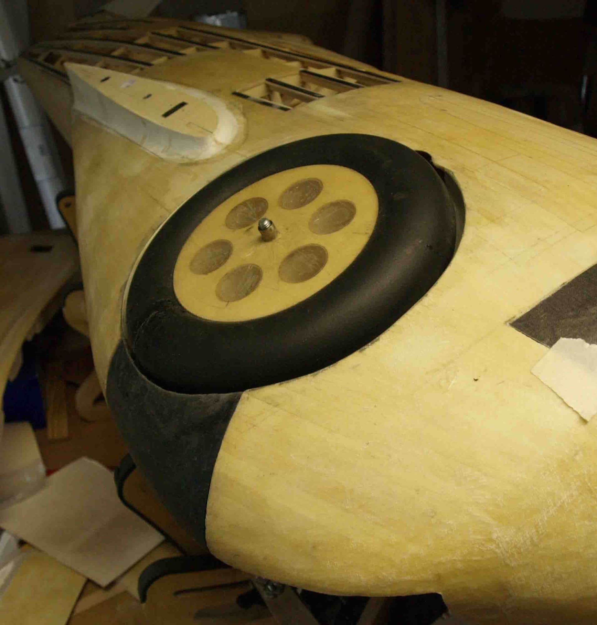
Now its all assembled. It looks nice, seems that this was a very quick amd simple thing. But I can say how often I assembled and disassambled the whole thing. The little clamb on the landing gear structure was very important. This was the movable part to fix it.
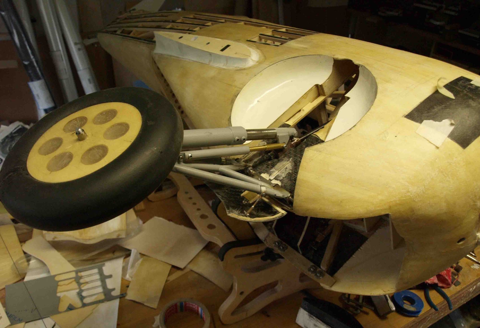
Closed and out, it works pretty nice.
this little video shows how it works
At first, I cutted some foam in form and sanded it.
the door itself was made of glass and carbon fiber, laminated direct on the fuselage/foam.
after cutting in shape I glued some wooden reinforcements in place
it fits quite well
some struts of brass
Now its all assembled. It looks nice, seems that this was a very quick amd simple thing. But I can say how often I assembled and disassambled the whole thing. The little clamb on the landing gear structure was very important. This was the movable part to fix it.
Closed and out, it works pretty nice.
this little video shows how it works
The following users liked this post:
mgnostic (09-21-2020)
09-21-2020, 10:22 PM
#90
Thread Starter
Join Date: Jan 2014
Location: Eppendorf, Saxonia, Germany
Posts: 129
Likes: 0
Received 7 Likes
on
7 Posts
Your praise embarasses me a little bit, thank you so much.
Now, the most of the"hard work" is done, I can start with some details.
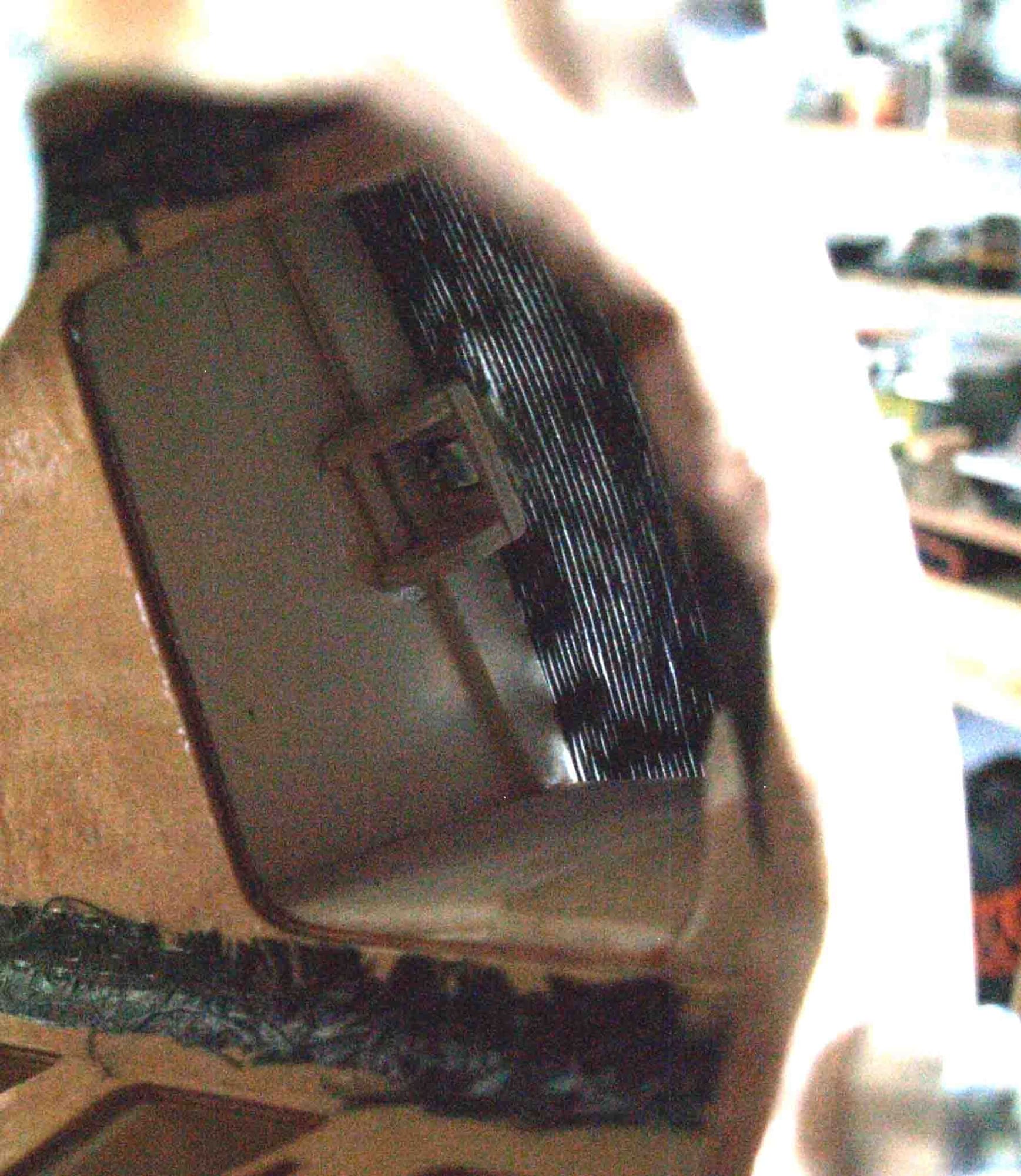
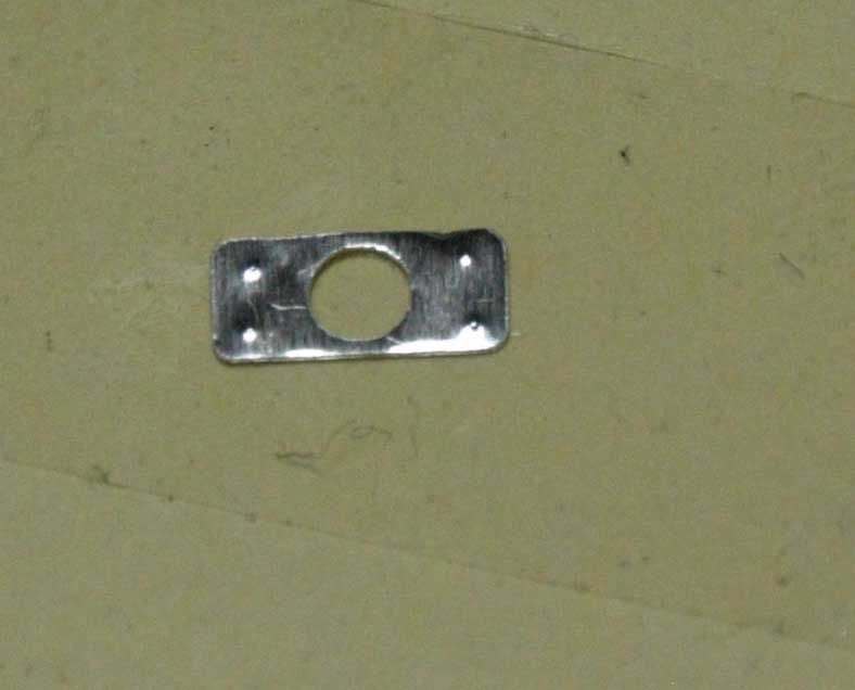
At first I finish the maintenance door. A time ago I laminated tehm on the fuse. So I cutted them in form and made a hinge out of steel wire.
I had many various ideas to manage the locking, finally I took a system from "Robbe", simply and safety.
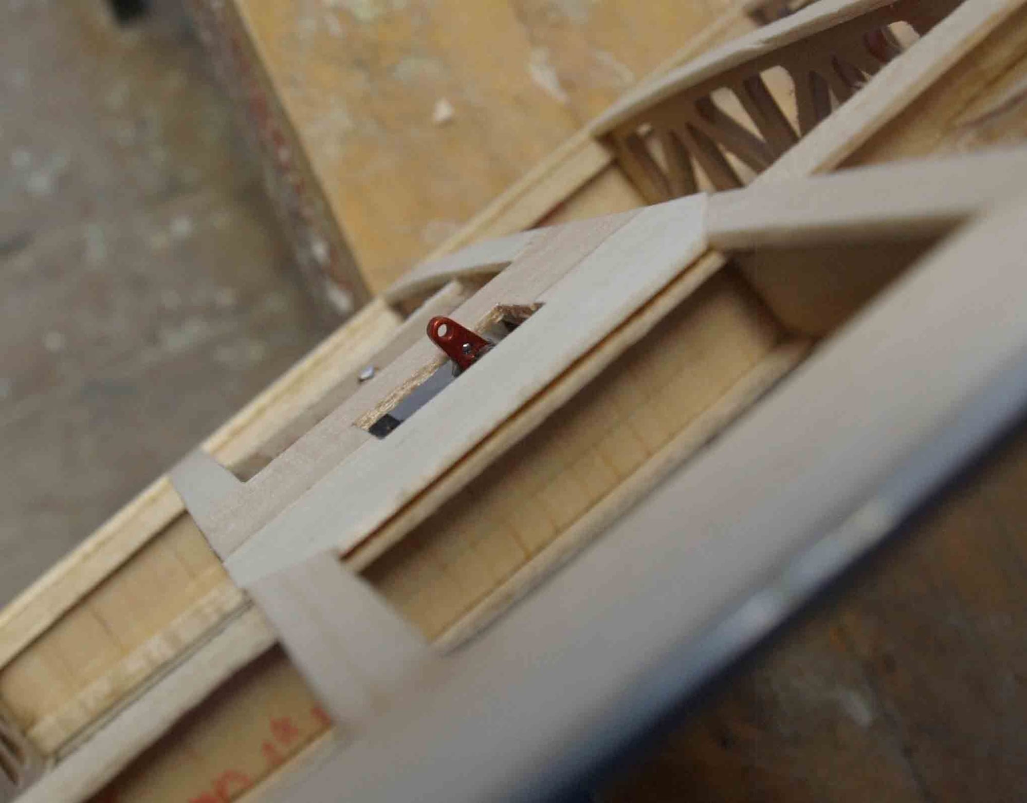
I started with a wooden bearing block
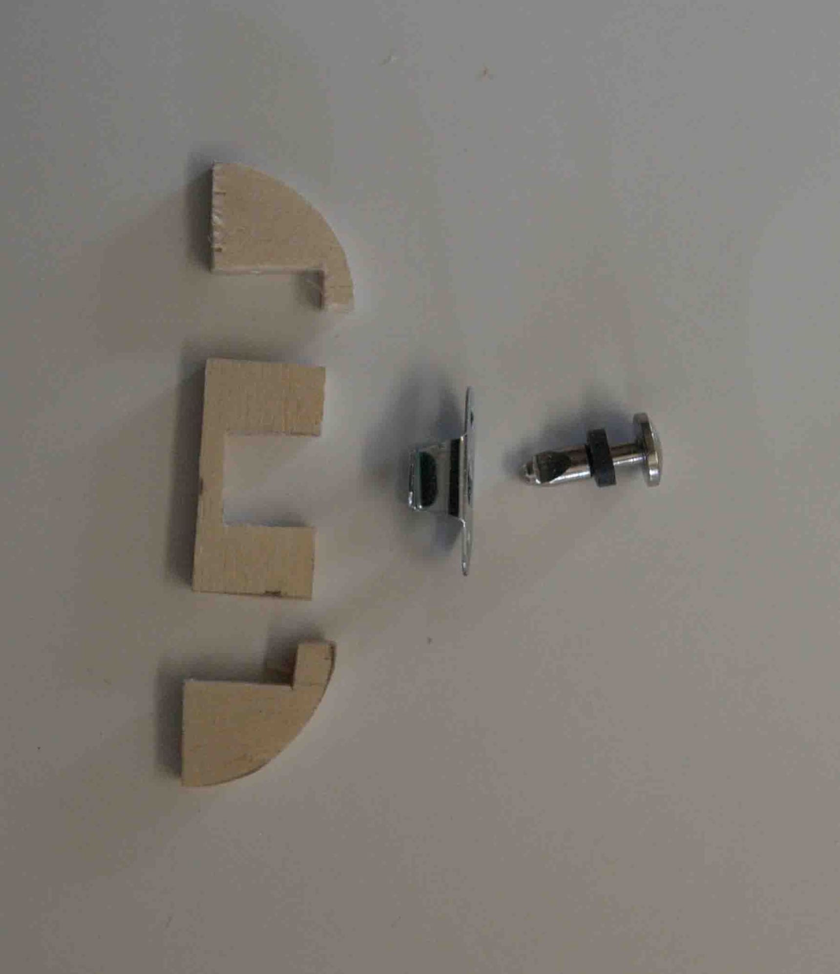
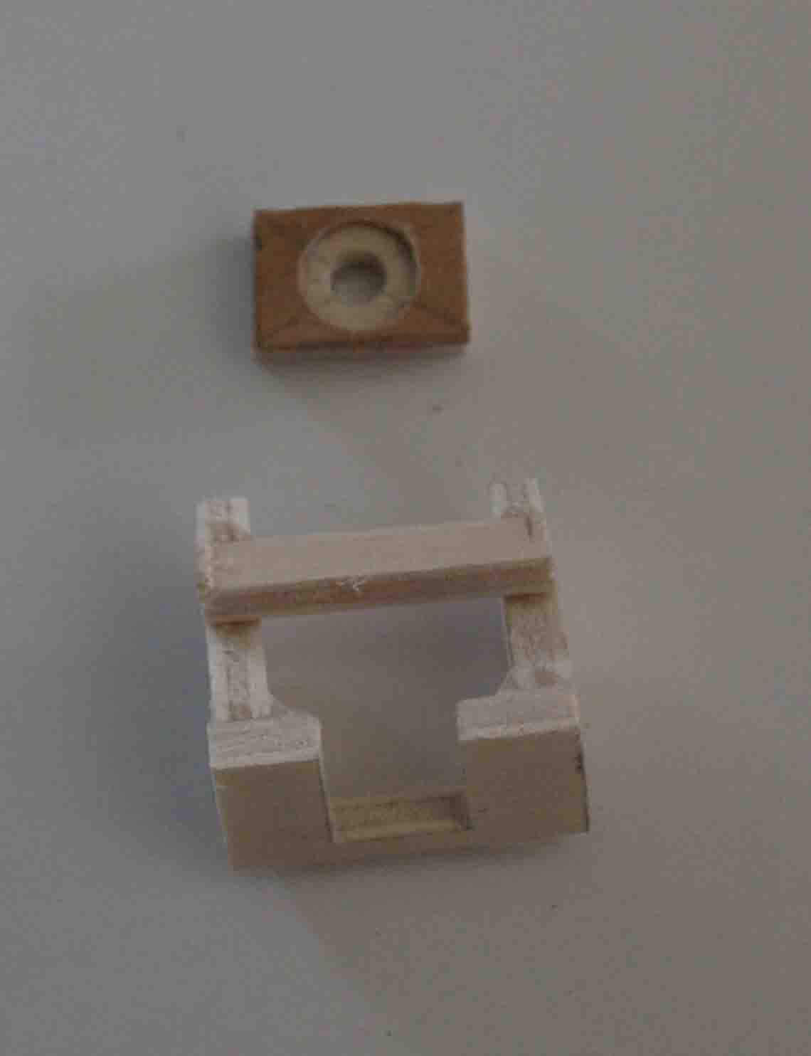
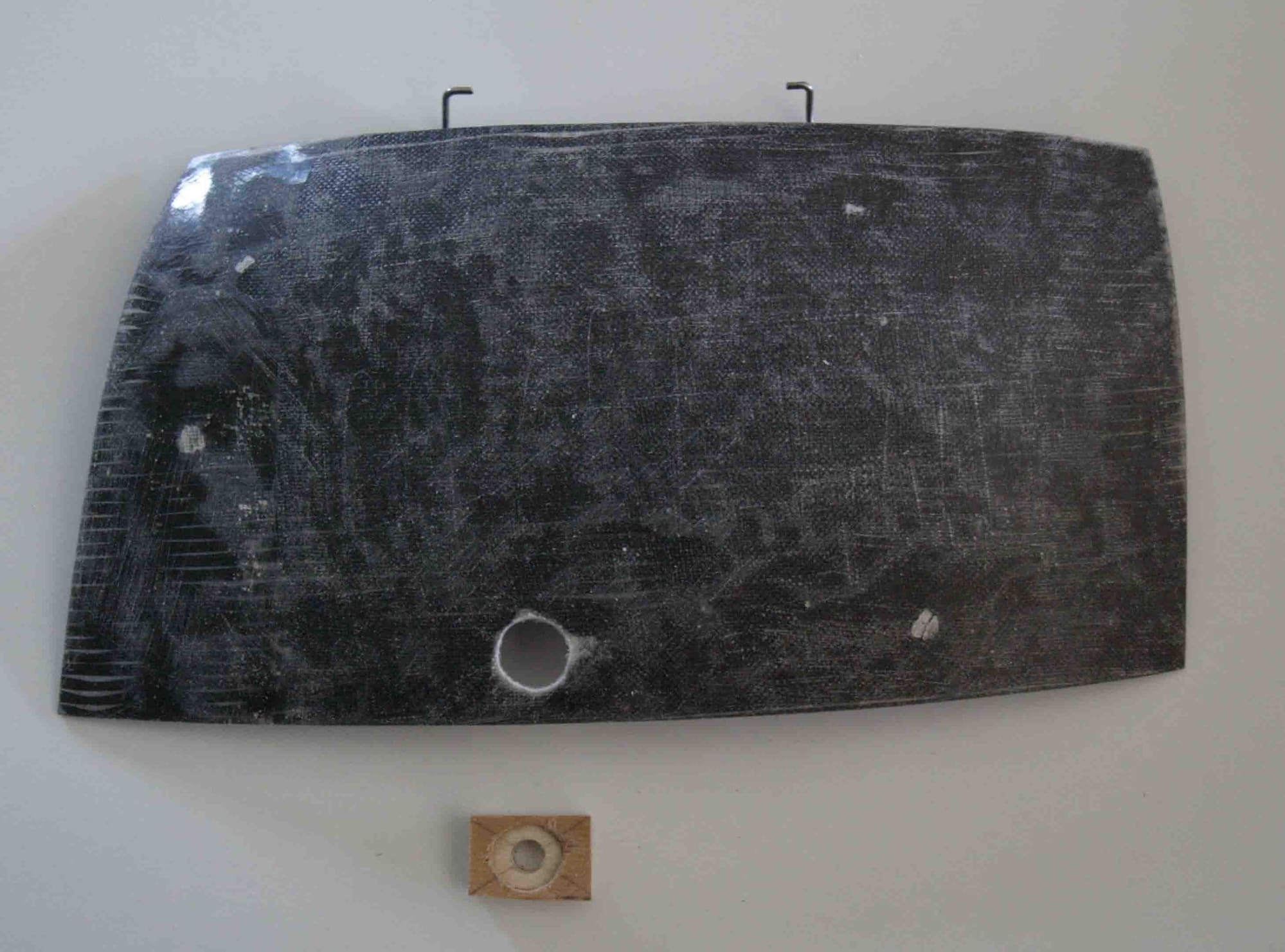
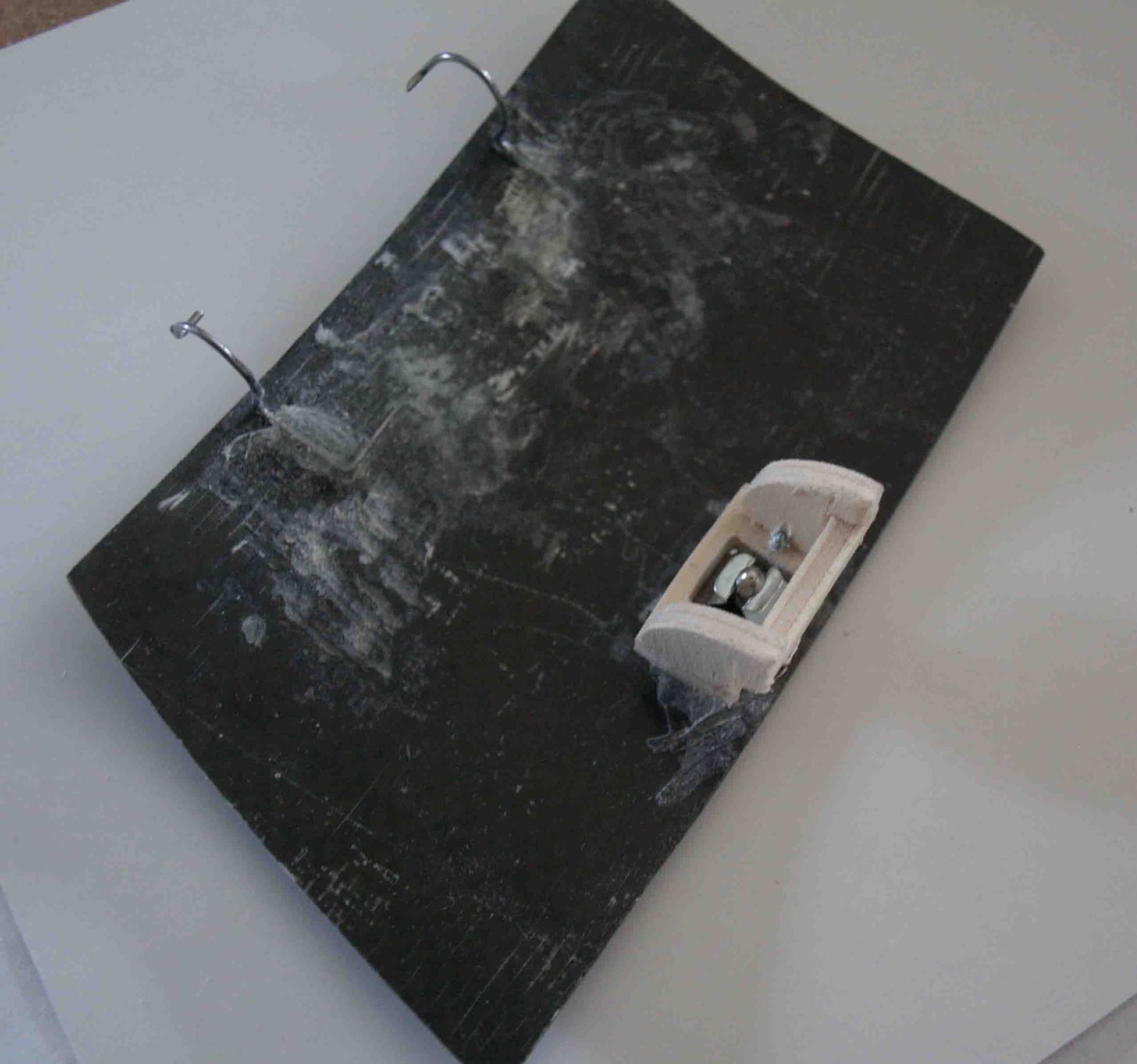
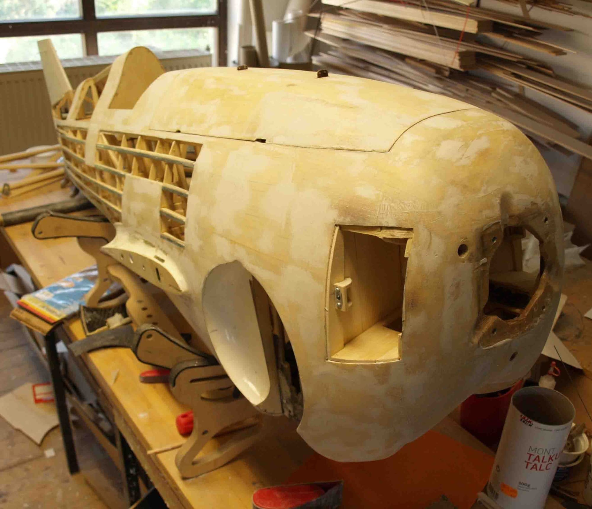
The bearing block installed into the fuselage.
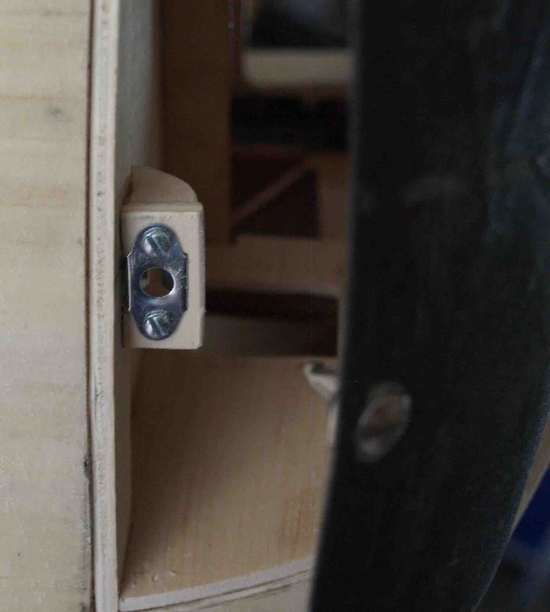
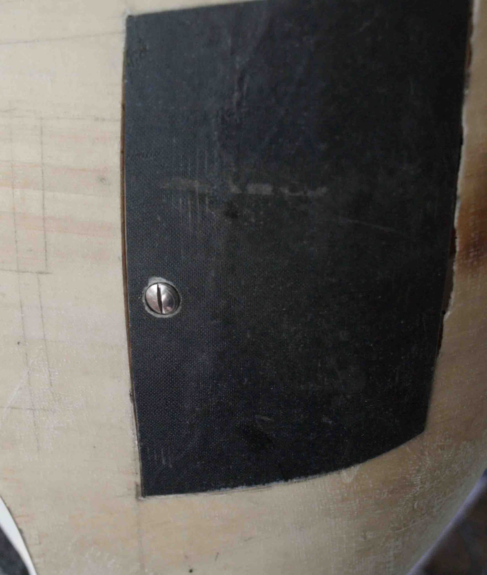
Finished. It is very easy to handle, simply a quarter turn with the screwdriver > open.To close it, simply press it in place
Now, the most of the"hard work" is done, I can start with some details.
At first I finish the maintenance door. A time ago I laminated tehm on the fuse. So I cutted them in form and made a hinge out of steel wire.
I had many various ideas to manage the locking, finally I took a system from "Robbe", simply and safety.
I started with a wooden bearing block
The bearing block installed into the fuselage.
Finished. It is very easy to handle, simply a quarter turn with the screwdriver > open.To close it, simply press it in place
Last edited by thomasmuckus; 09-22-2020 at 12:34 AM.
09-22-2020, 01:13 AM
#91
Thread Starter
Join Date: Jan 2014
Location: Eppendorf, Saxonia, Germany
Posts: 129
Likes: 0
Received 7 Likes
on
7 Posts
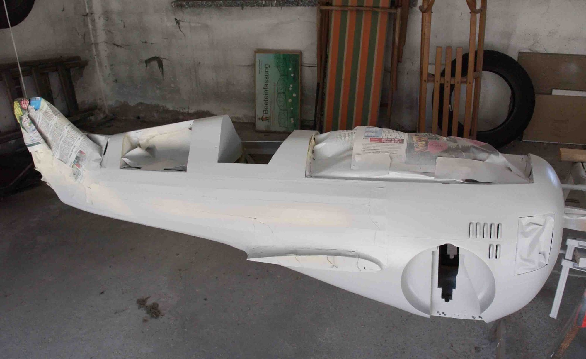
o.k., looks like I`m a quick worker, no I`m a laty writer. Fortunately I made any pics.
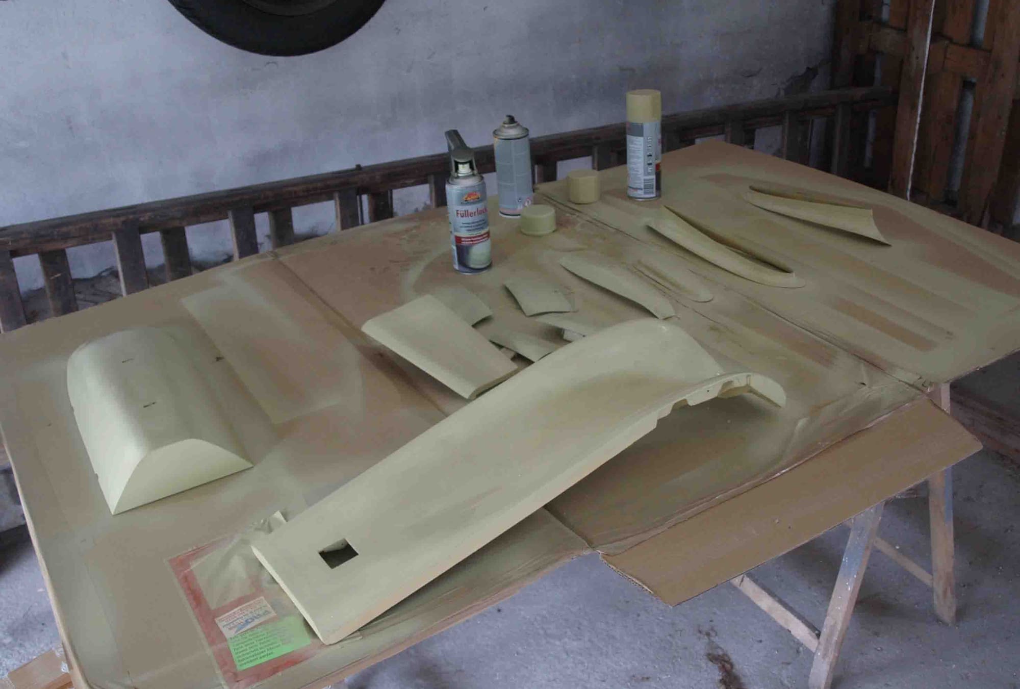
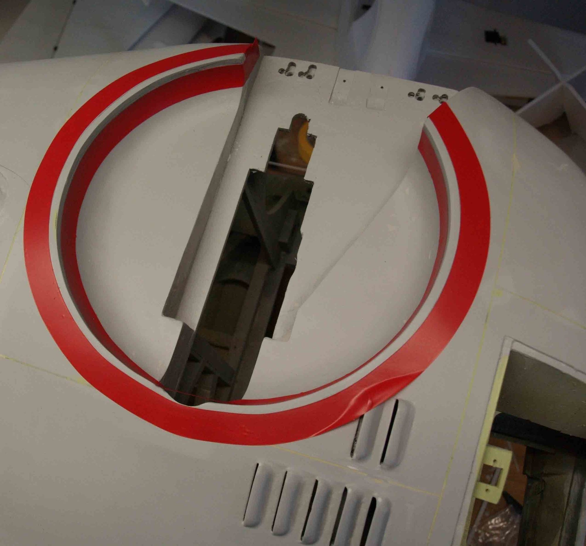
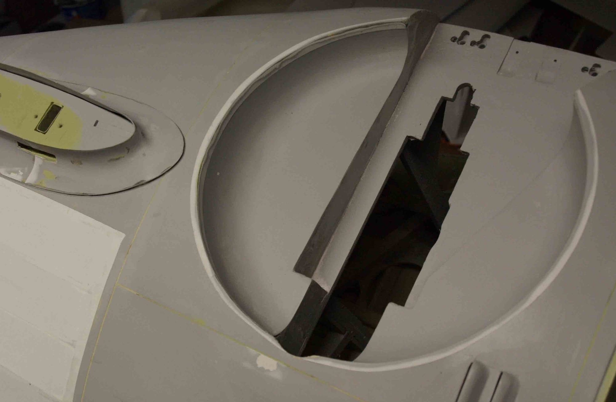
Before ivering the fuselage, I sprayed the first layer with filler primer to smooth the surface.
Now tho open parts are covered with Oratex
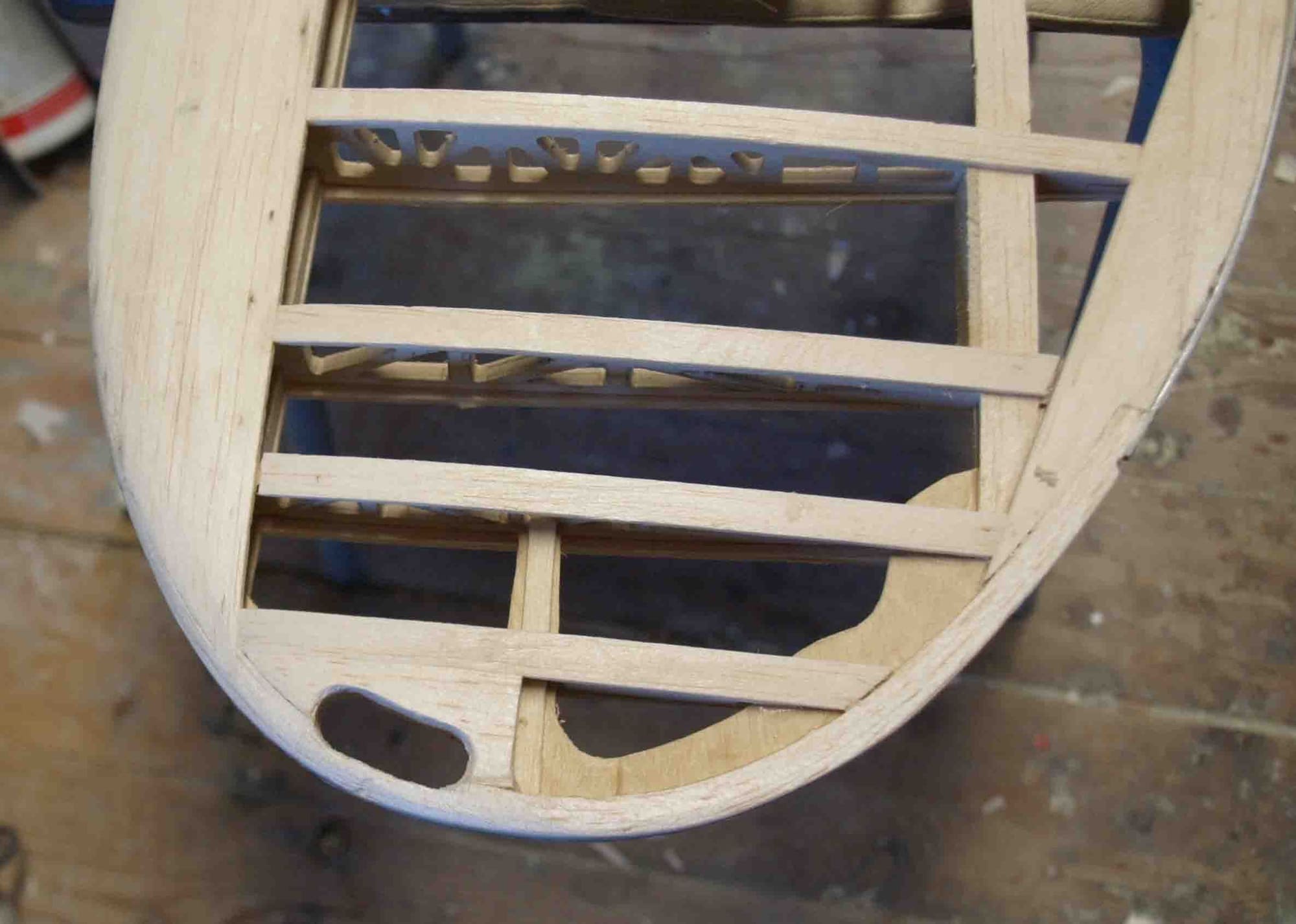
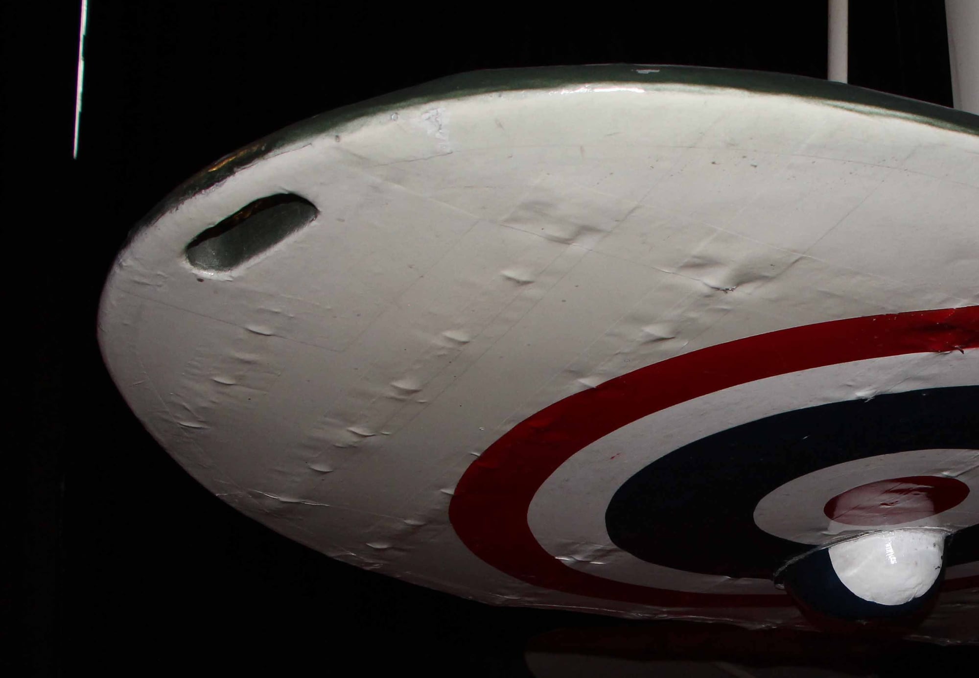
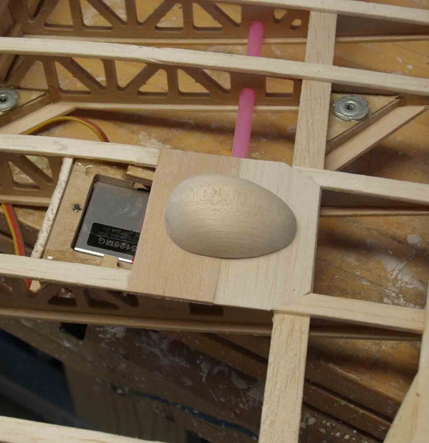
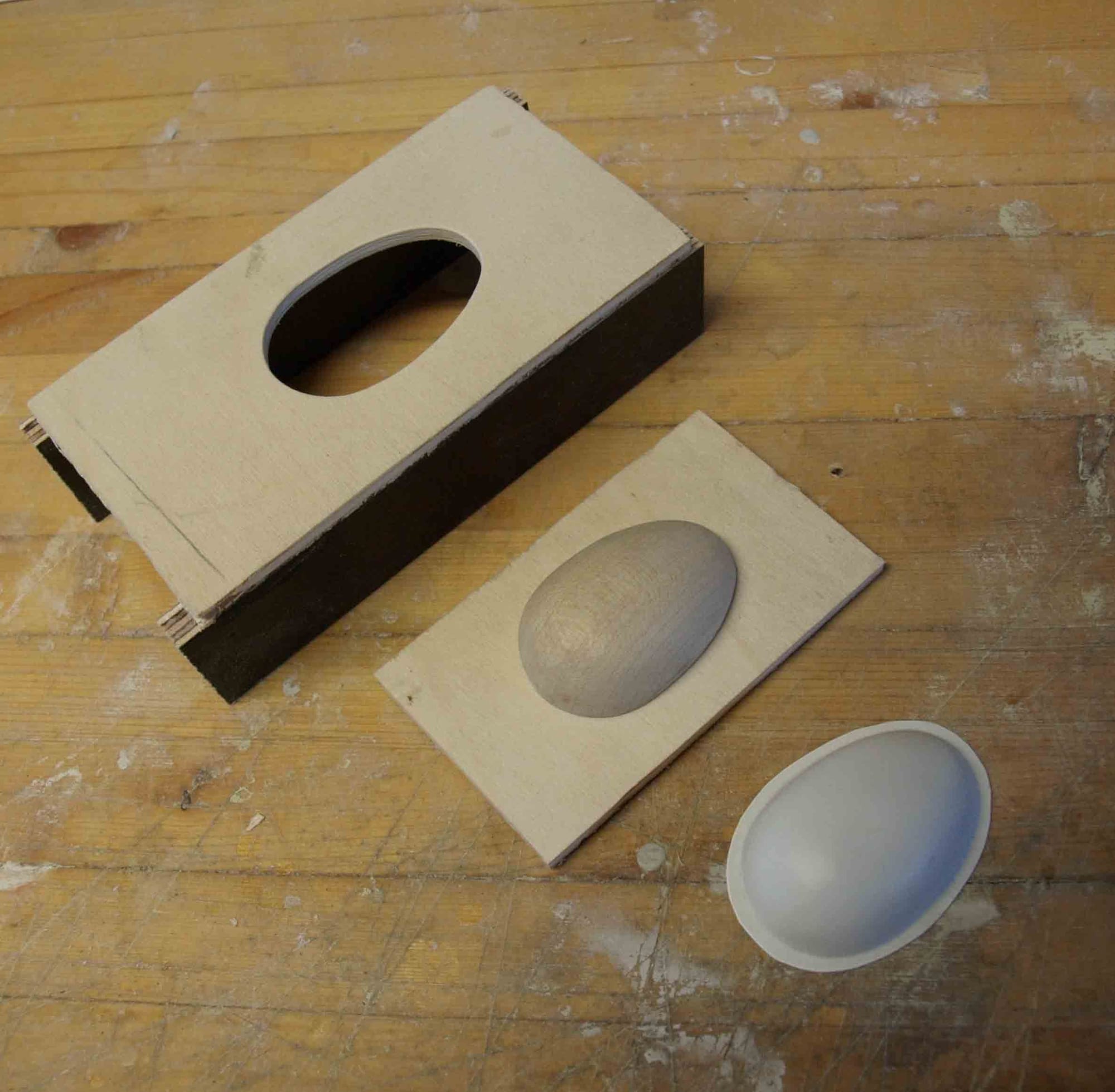
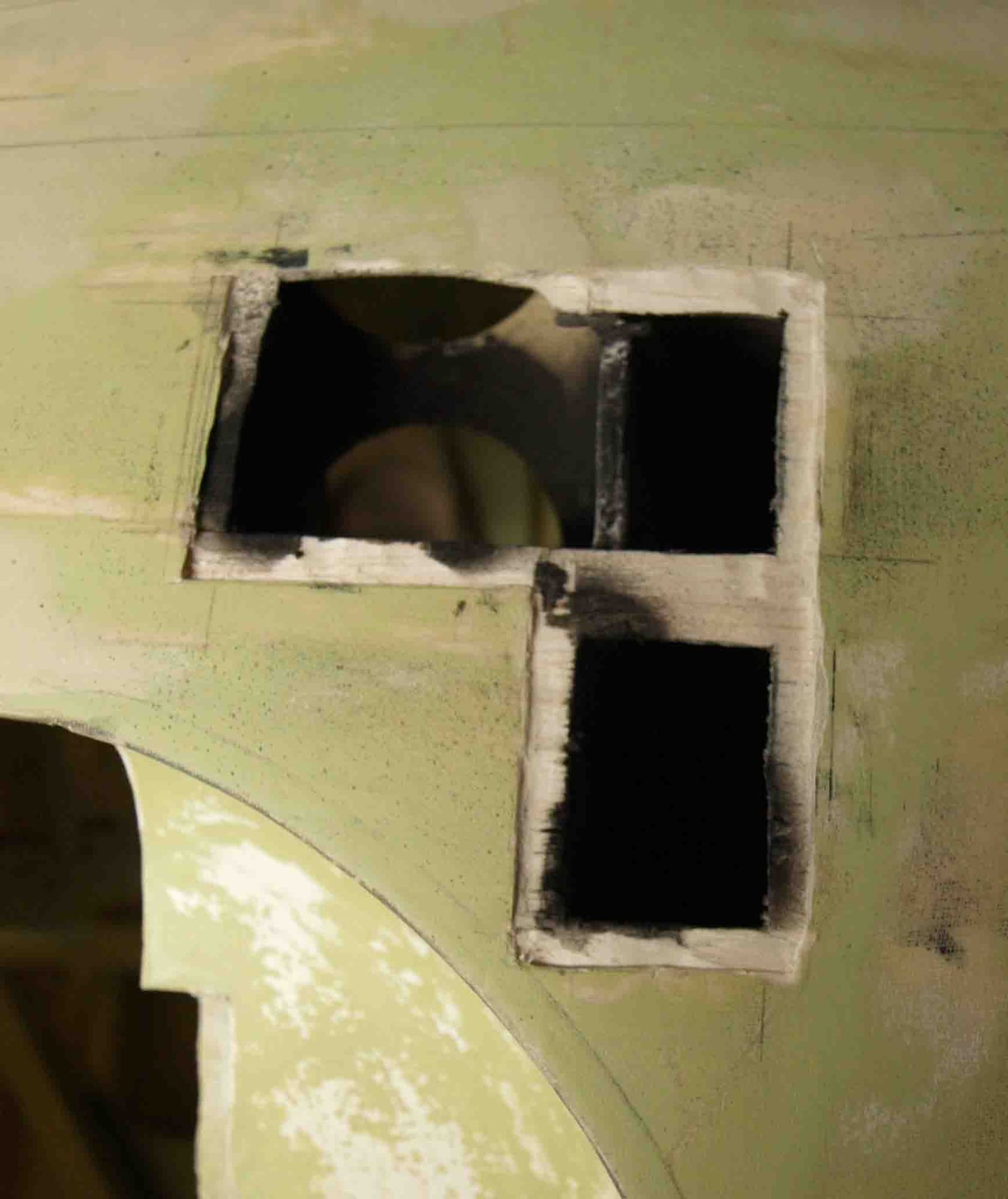
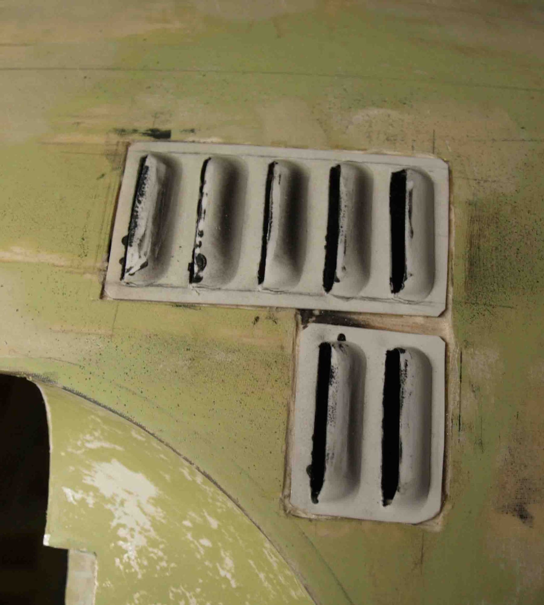
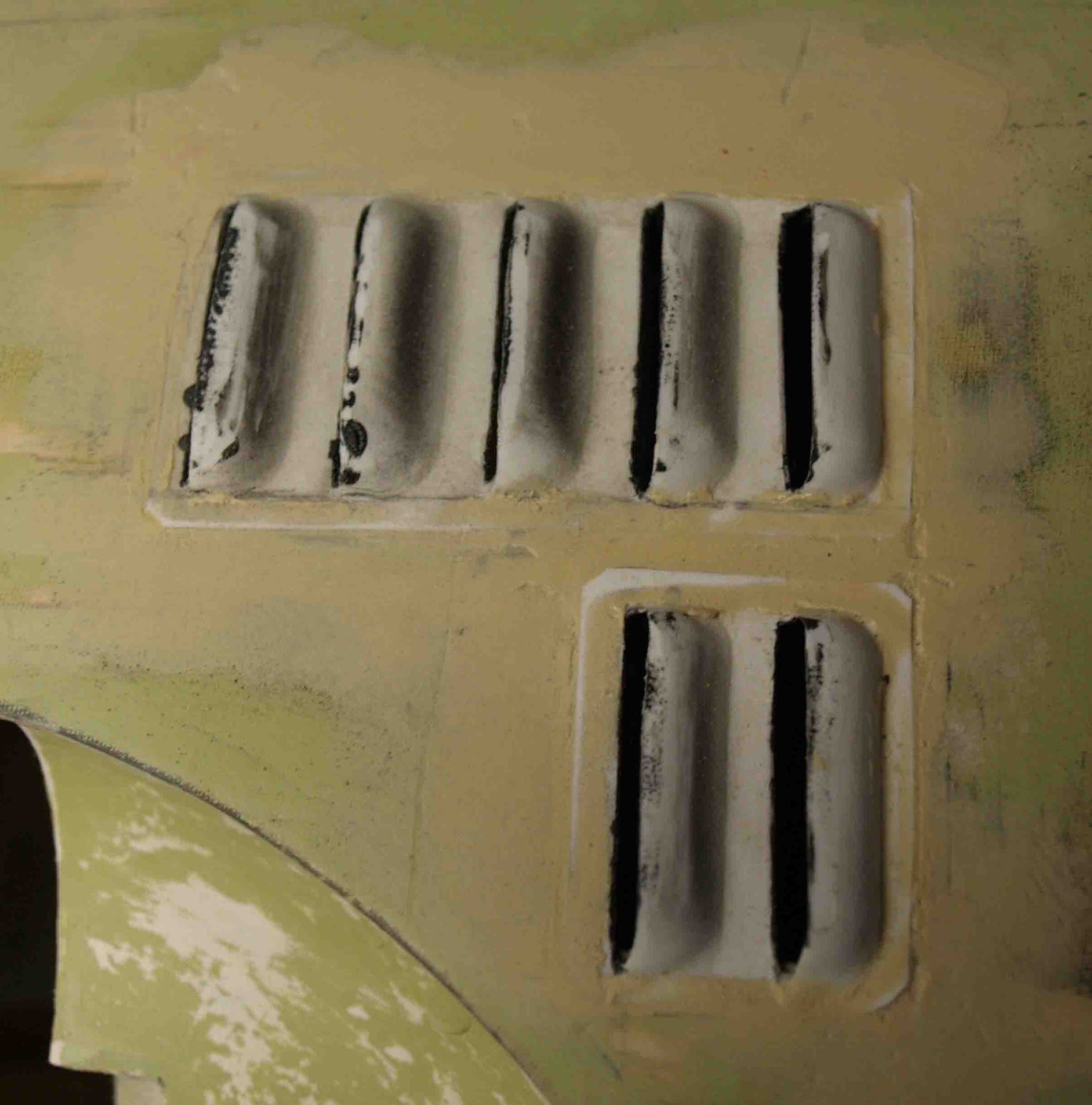
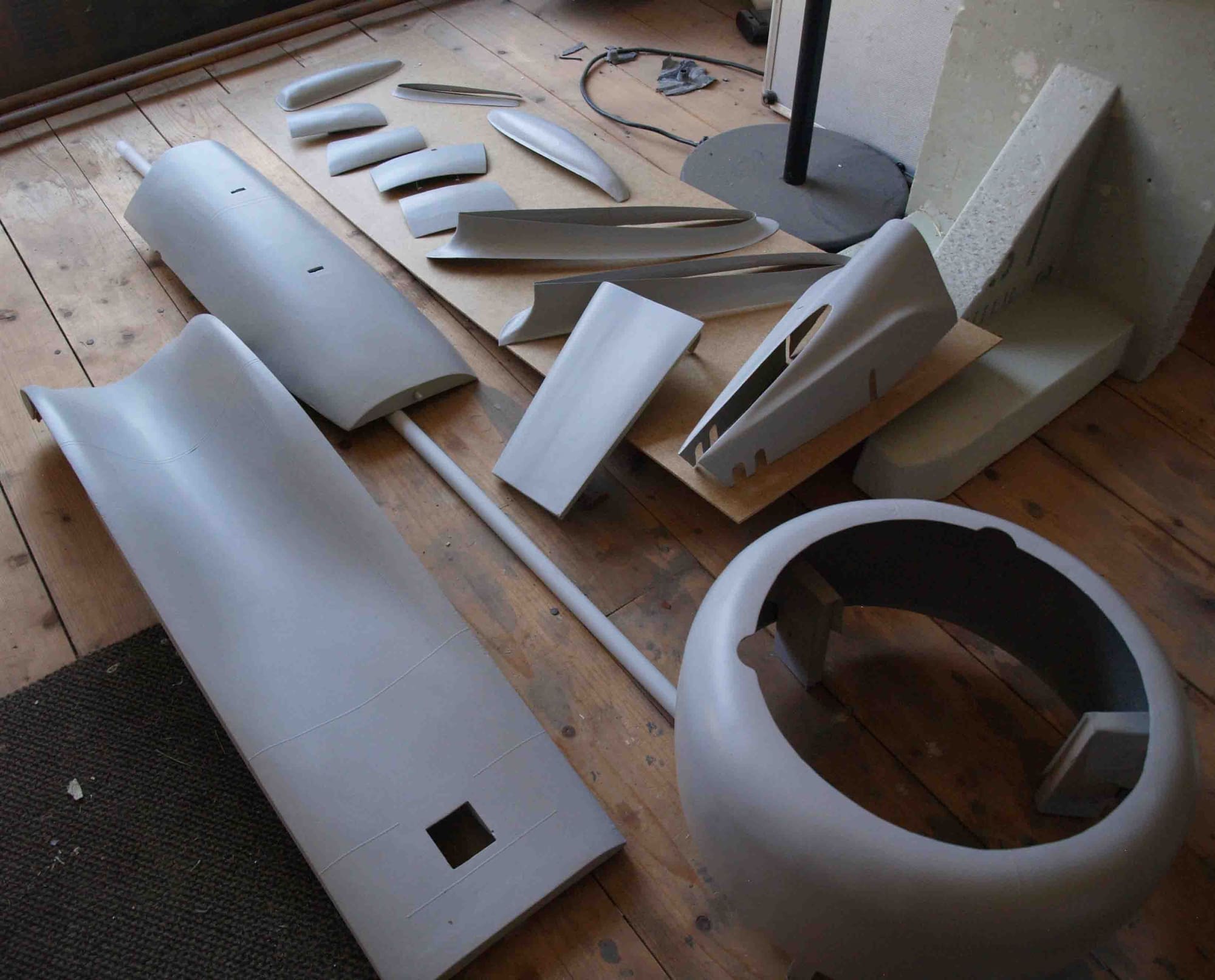
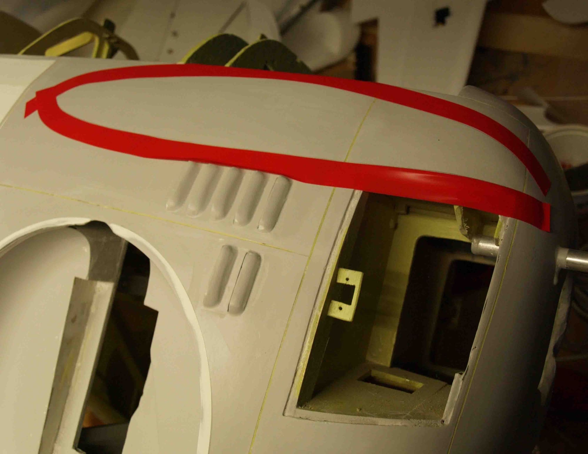
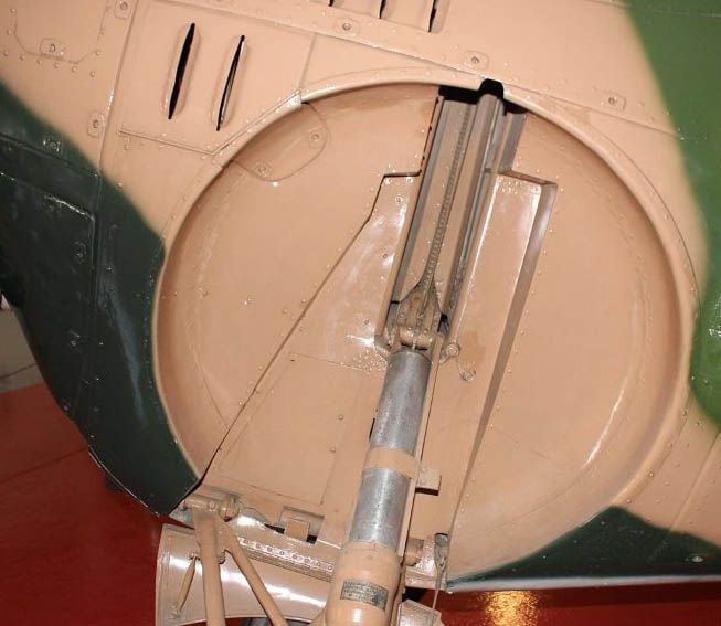
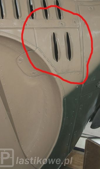
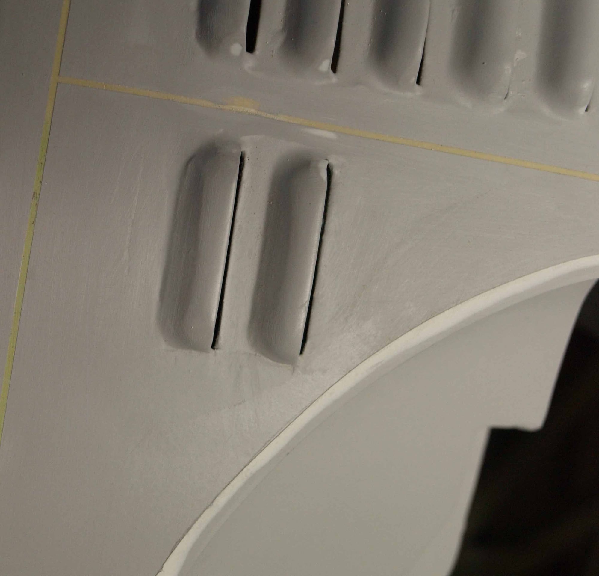
The next step was building of those ventilation slots. One of my friends in our modelling club printed me such a part. Pretty nice but it looks to clear. If you look at the original you will understand wht I mean.
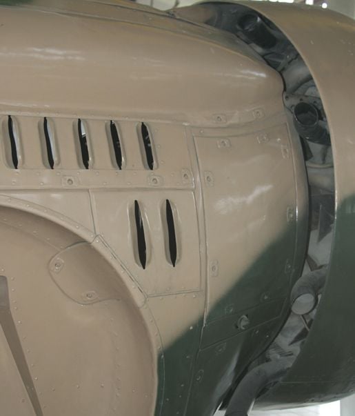
So I used it as mould, made a tool and the were deep drawm of ABS.
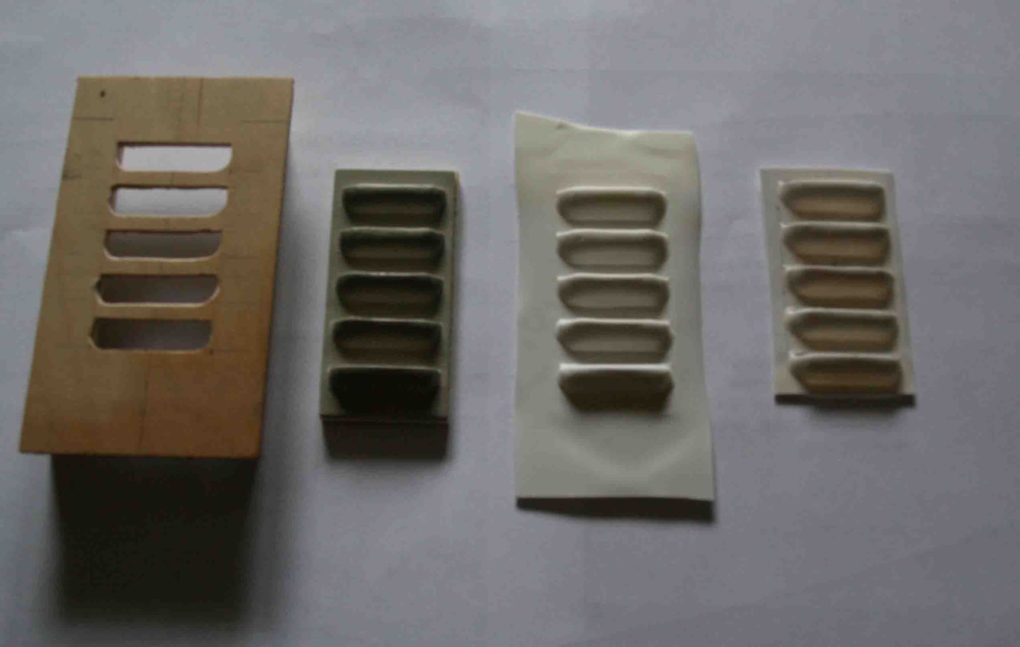
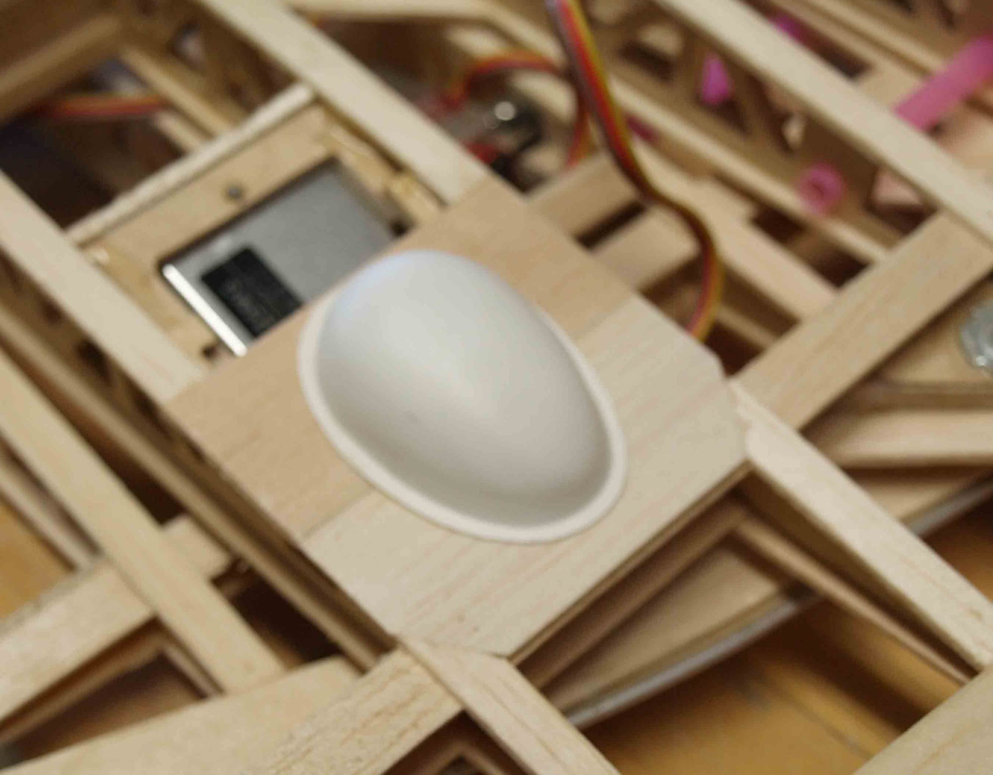
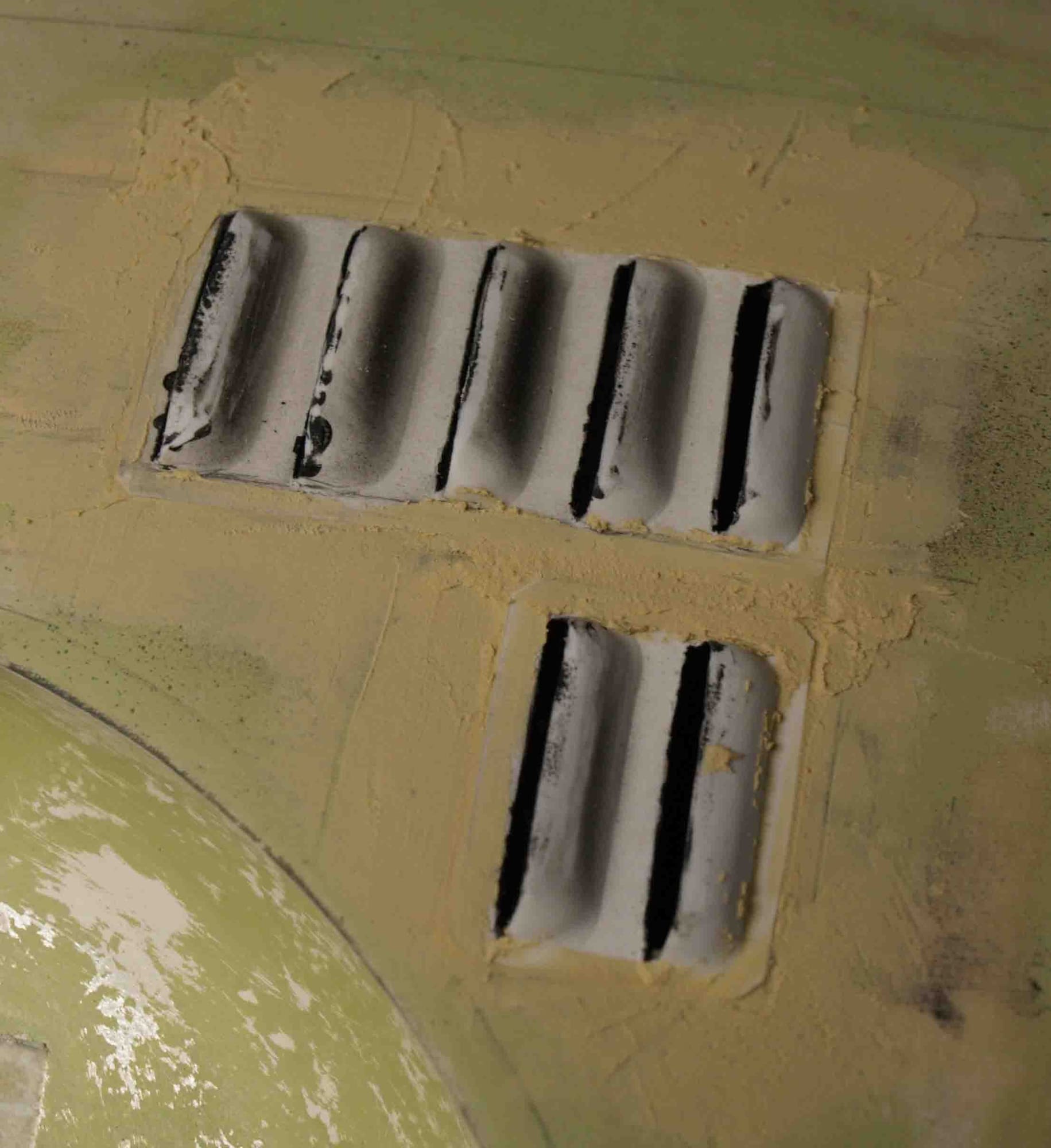
the rest is very simple......
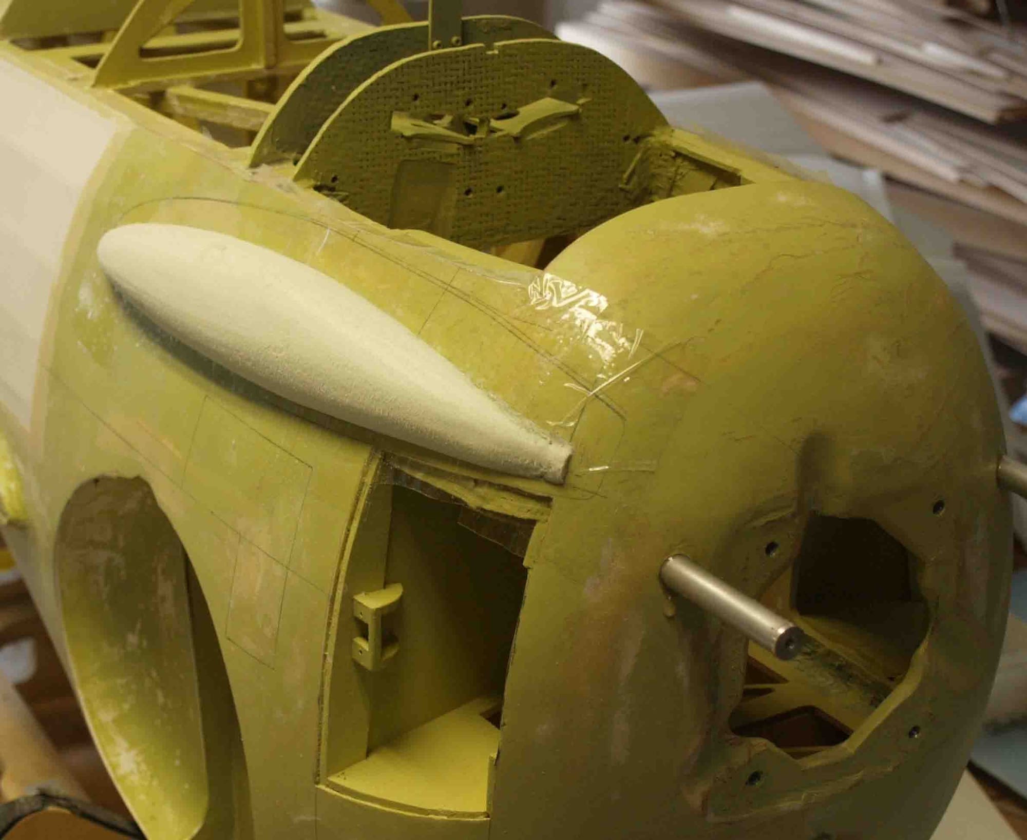
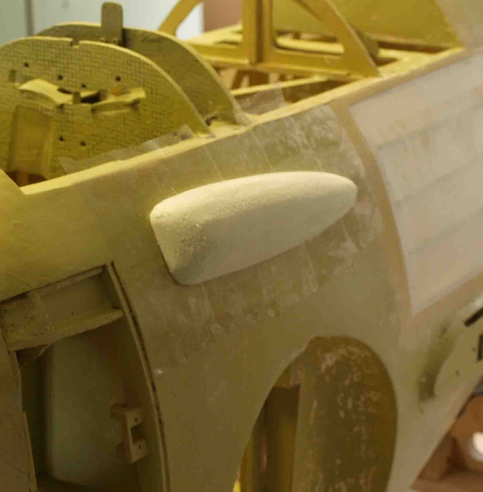
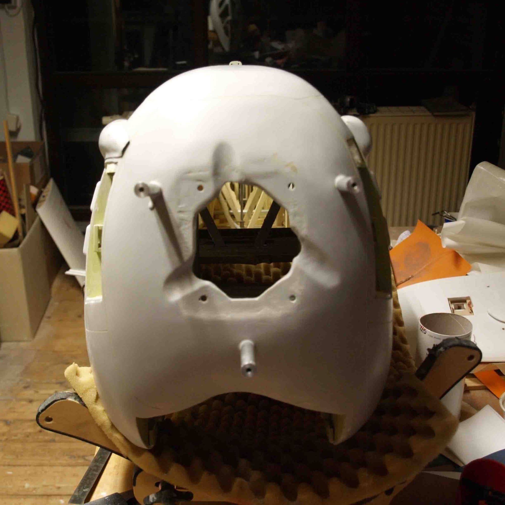
o.k., it`s a warbird and so it needs some arament. There are two gunblisters, I haven't found out until today why the are not symmetrical....
I`made them like all other additional parts, lamminated directly on the fuselage, the core ist Styrodur, a hard foam.

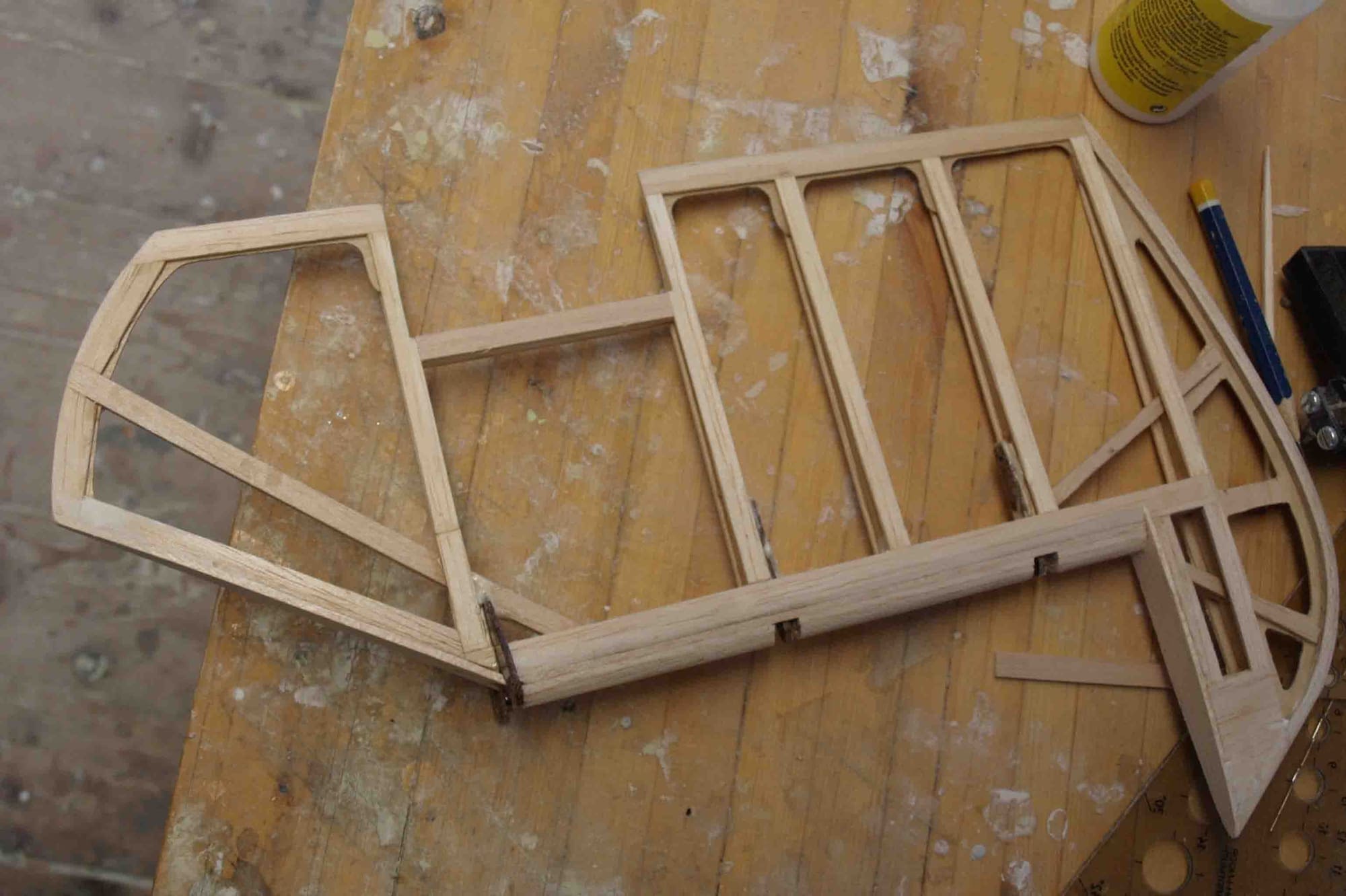
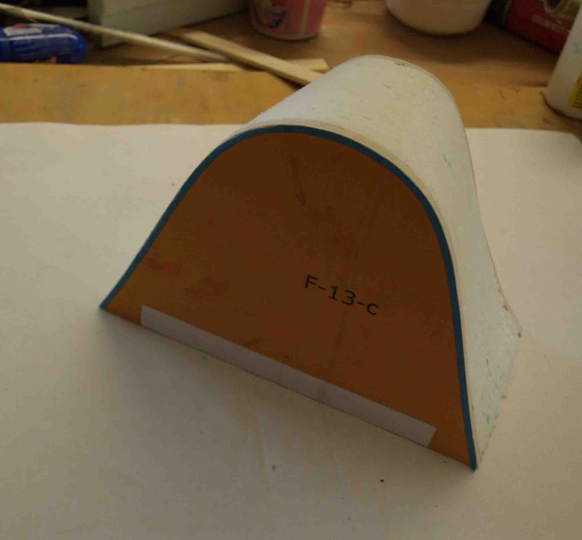
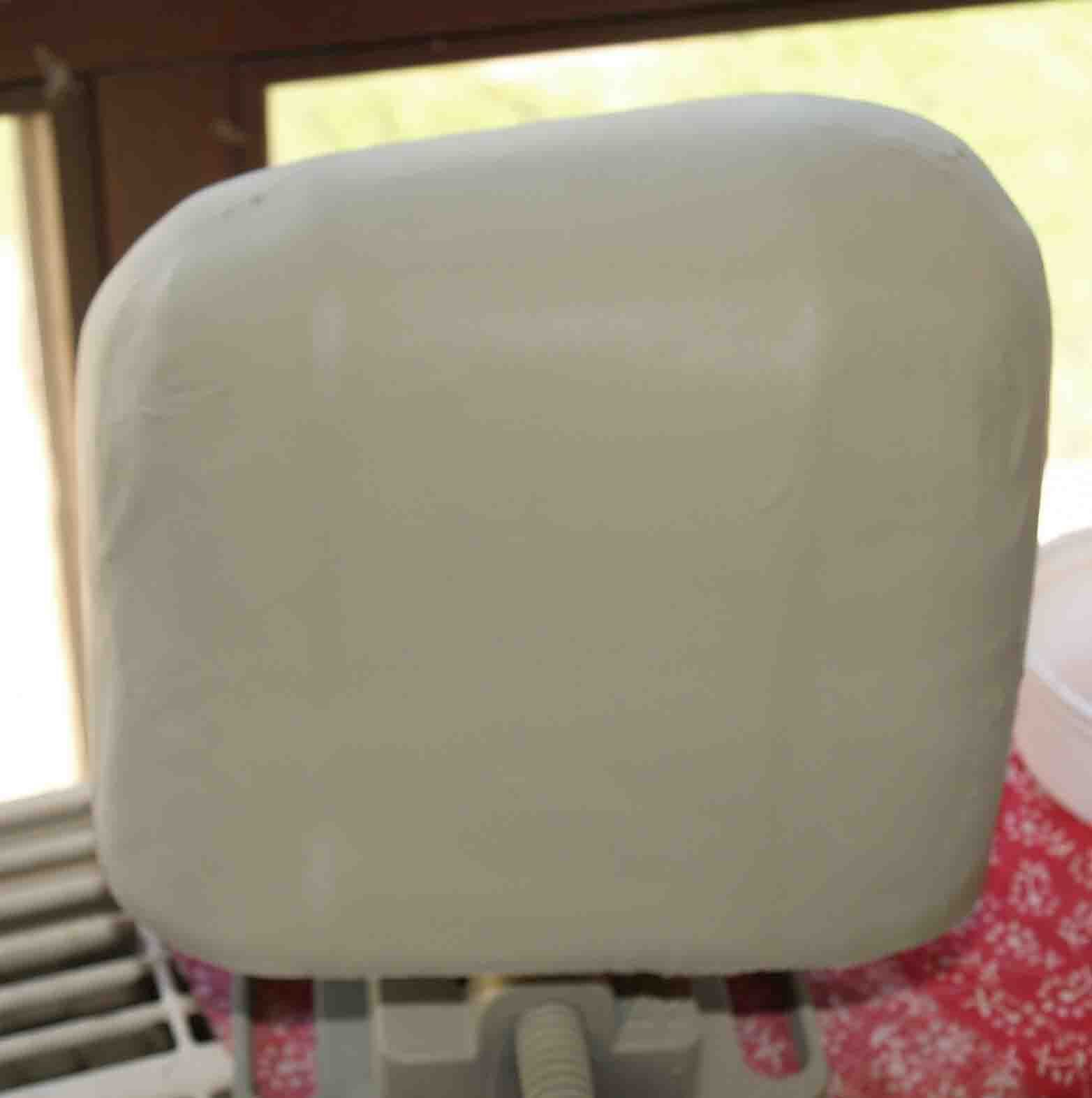
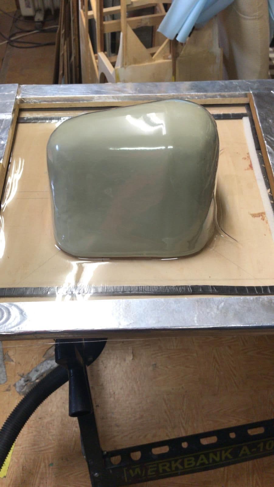
the rear part of the canopy I deep draw . There was a model to build, I made this also from plywood and Styrodur, covered with fiberglas. Deep drawing of such bigger parts is sometime a little bit tricky, fortunately it works at firtst attempt
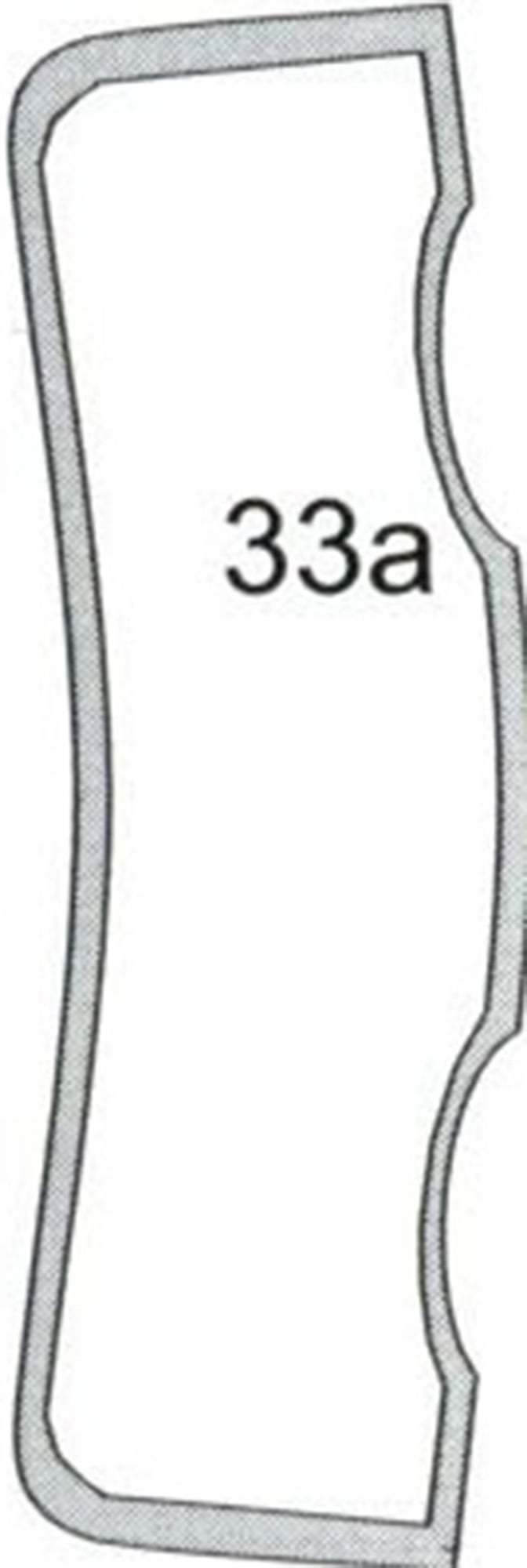
As template for the canopy and for the frame I use a paper cut modell.
. Fortunately I made any pics.Before ivering the fuselage, I sprayed the first layer with filler primer to smooth the surface.
Now tho open parts are covered with Oratex
The next step was building of those ventilation slots. One of my friends in our modelling club printed me such a part. Pretty nice but it looks to clear. If you look at the original you will understand wht I mean.
So I used it as mould, made a tool and the were deep drawm of ABS.
the rest is very simple......
o.k., it`s a warbird and so it needs some arament. There are two gunblisters, I haven't found out until today why the are not symmetrical....
I`made them like all other additional parts, lamminated directly on the fuselage, the core ist Styrodur, a hard foam.
the rear part of the canopy I deep draw . There was a model to build, I made this also from plywood and Styrodur, covered with fiberglas. Deep drawing of such bigger parts is sometime a little bit tricky, fortunately it works at firtst attempt
As template for the canopy and for the frame I use a paper cut modell.
09-22-2020, 10:02 AM
#93
Thread Starter
Join Date: Jan 2014
Location: Eppendorf, Saxonia, Germany
Posts: 129
Likes: 0
Received 7 Likes
on
7 Posts
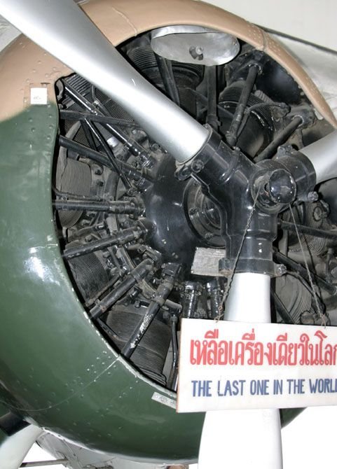
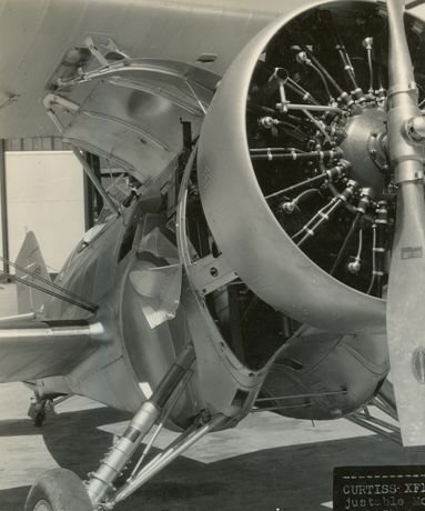
one of the dominant parts is the nine-cylinder engine. My SAITO had only 3. Is not a problem, i.m.o the sound of this tree-cylinder is realy cool. At first I took a simply deep drawn dummy but is tooks terrible.
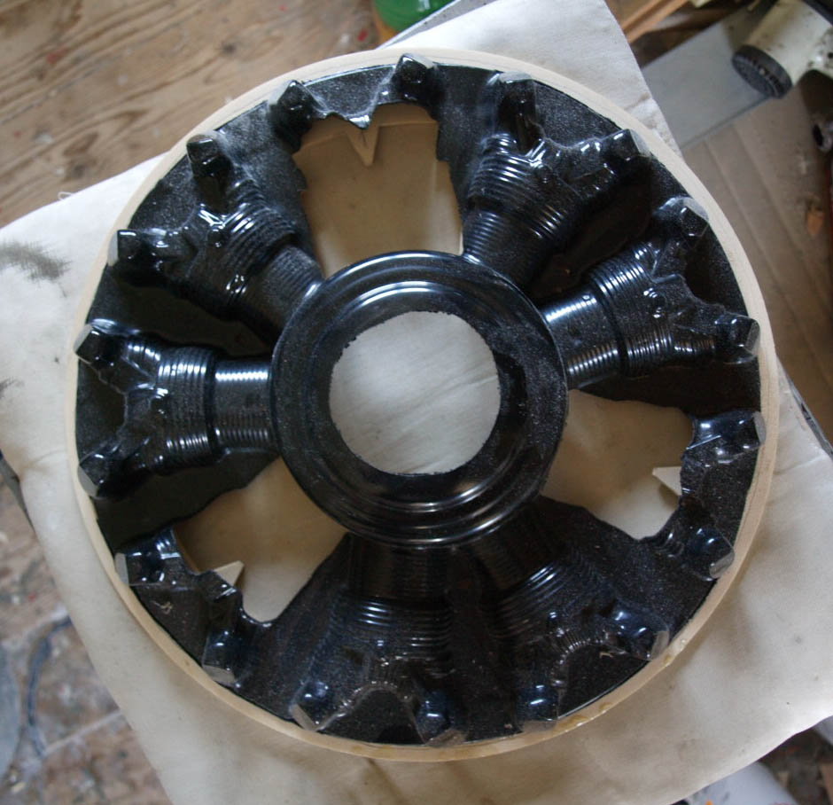
Then, I was searching the www and found a dummy-engine : https://modellstudio.de/epages/4ff94...oducts/6830800
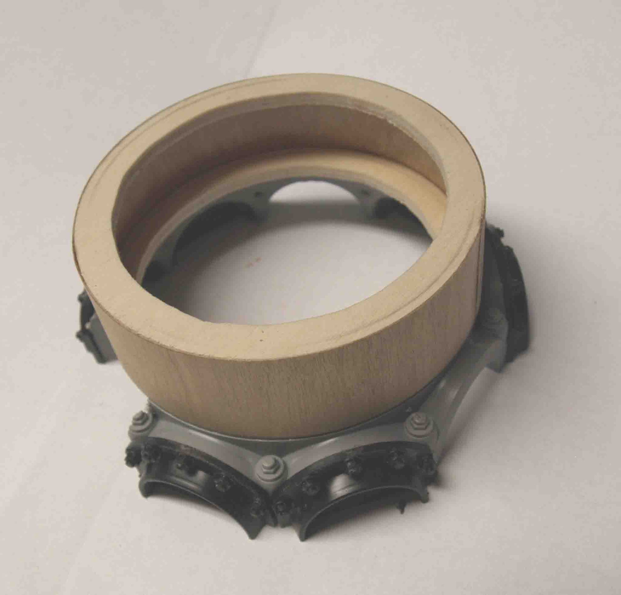
This kit is not cheap but realy great, many details and the best thing of all: the diameter is close to my SAITO.
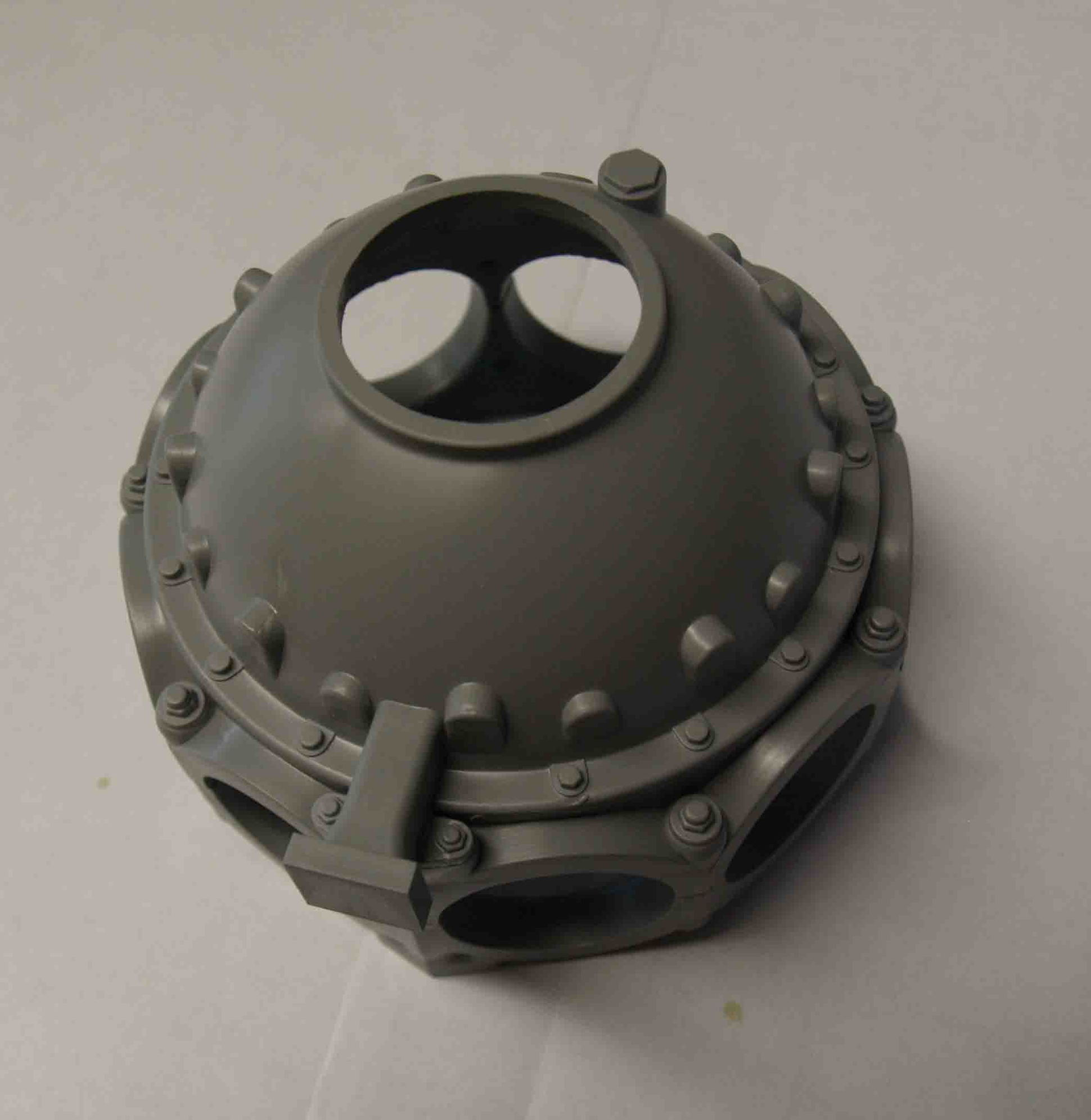
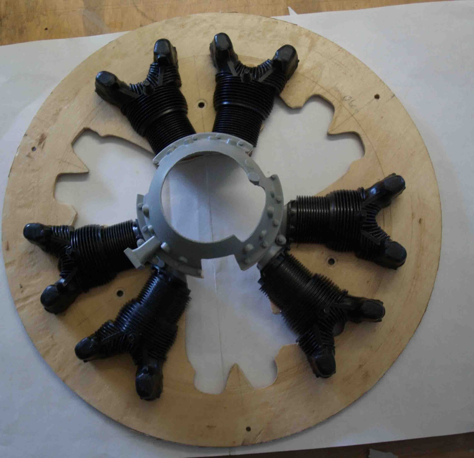
At first I had to optimize the chrankcase. Pictures says more than words
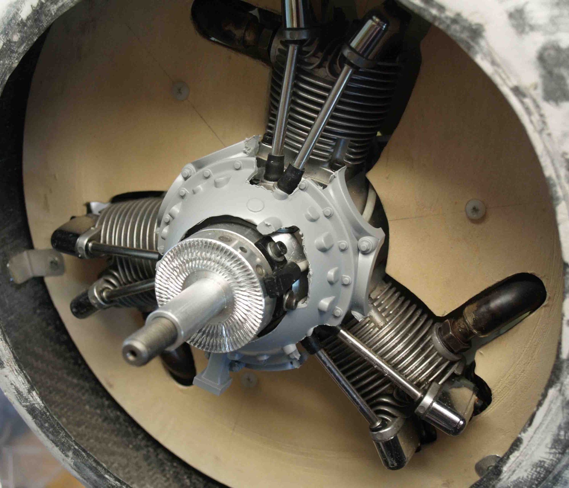
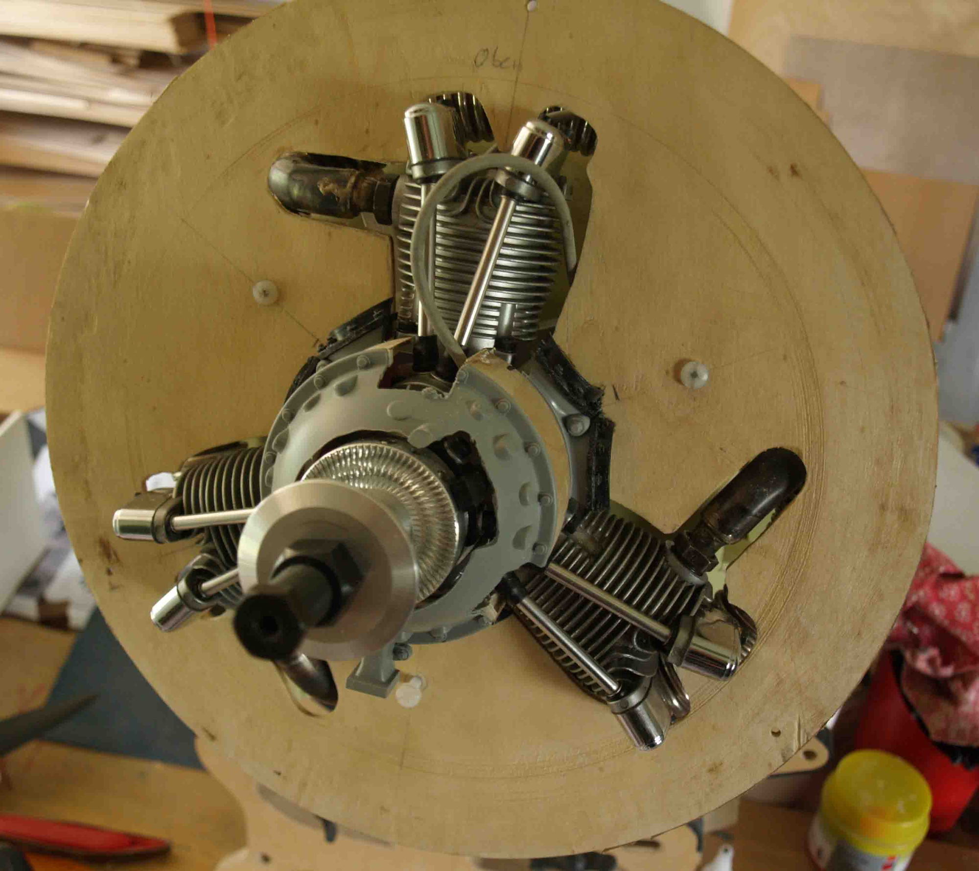
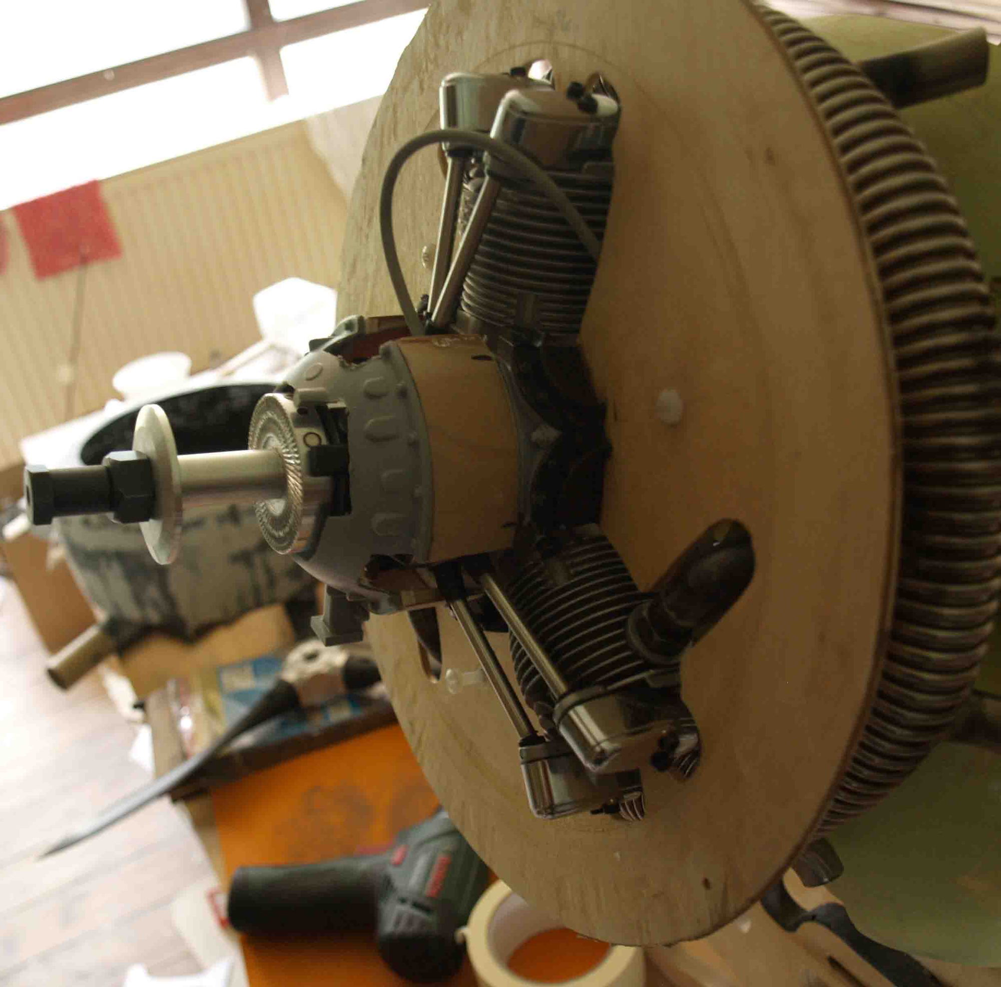
after preparing the zylinders
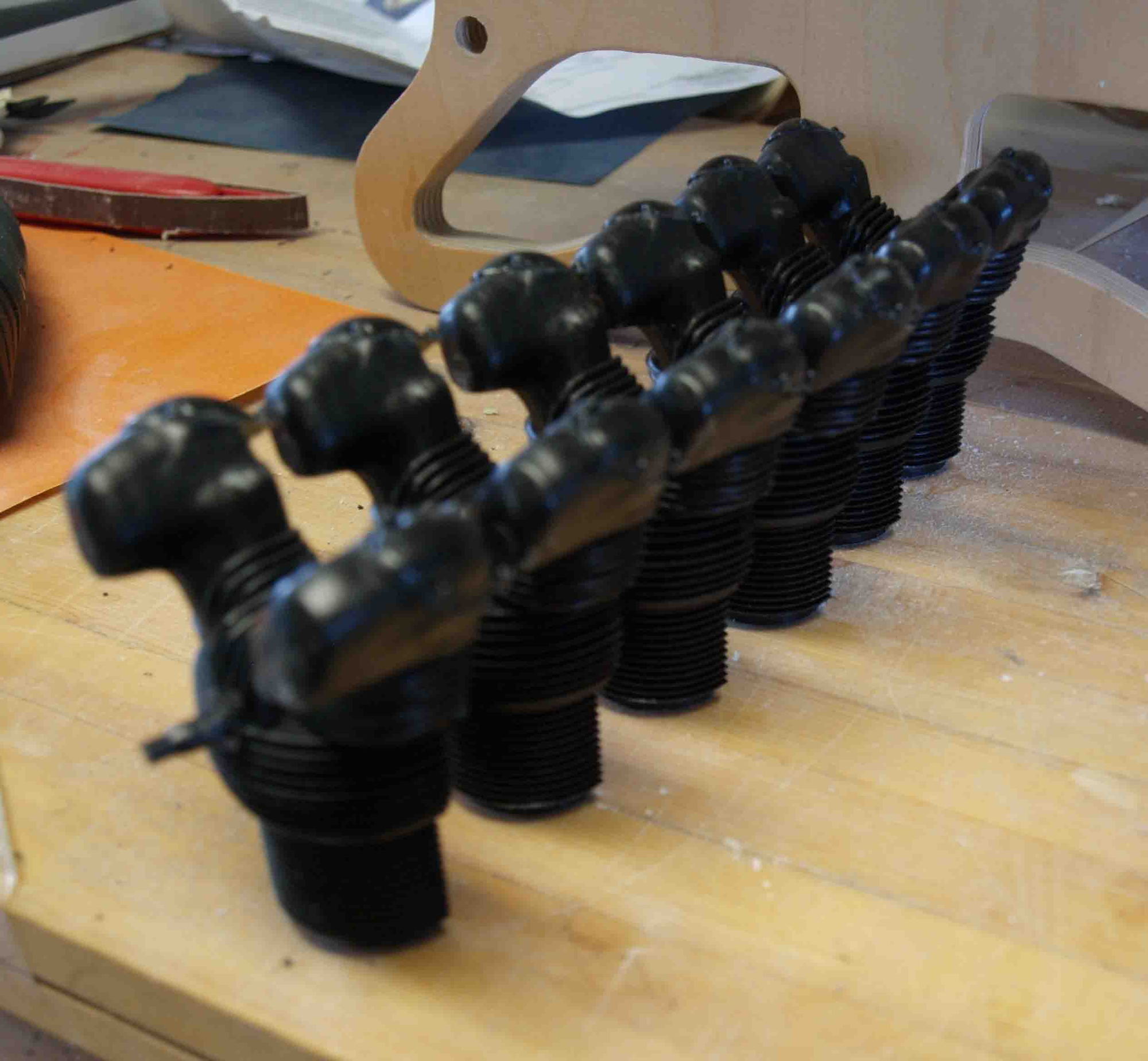
they were glued in place
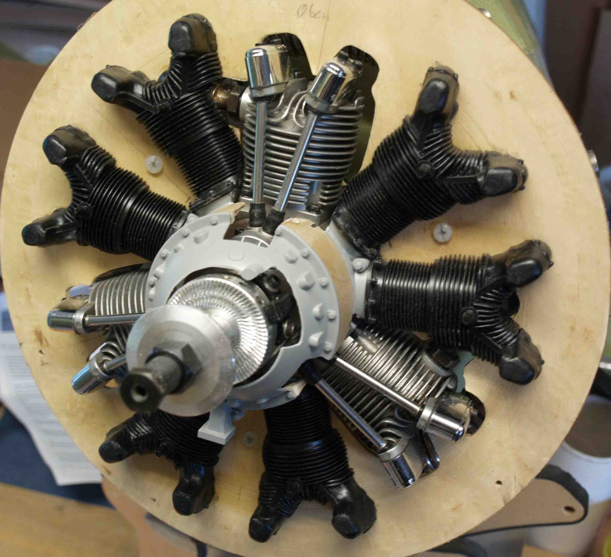
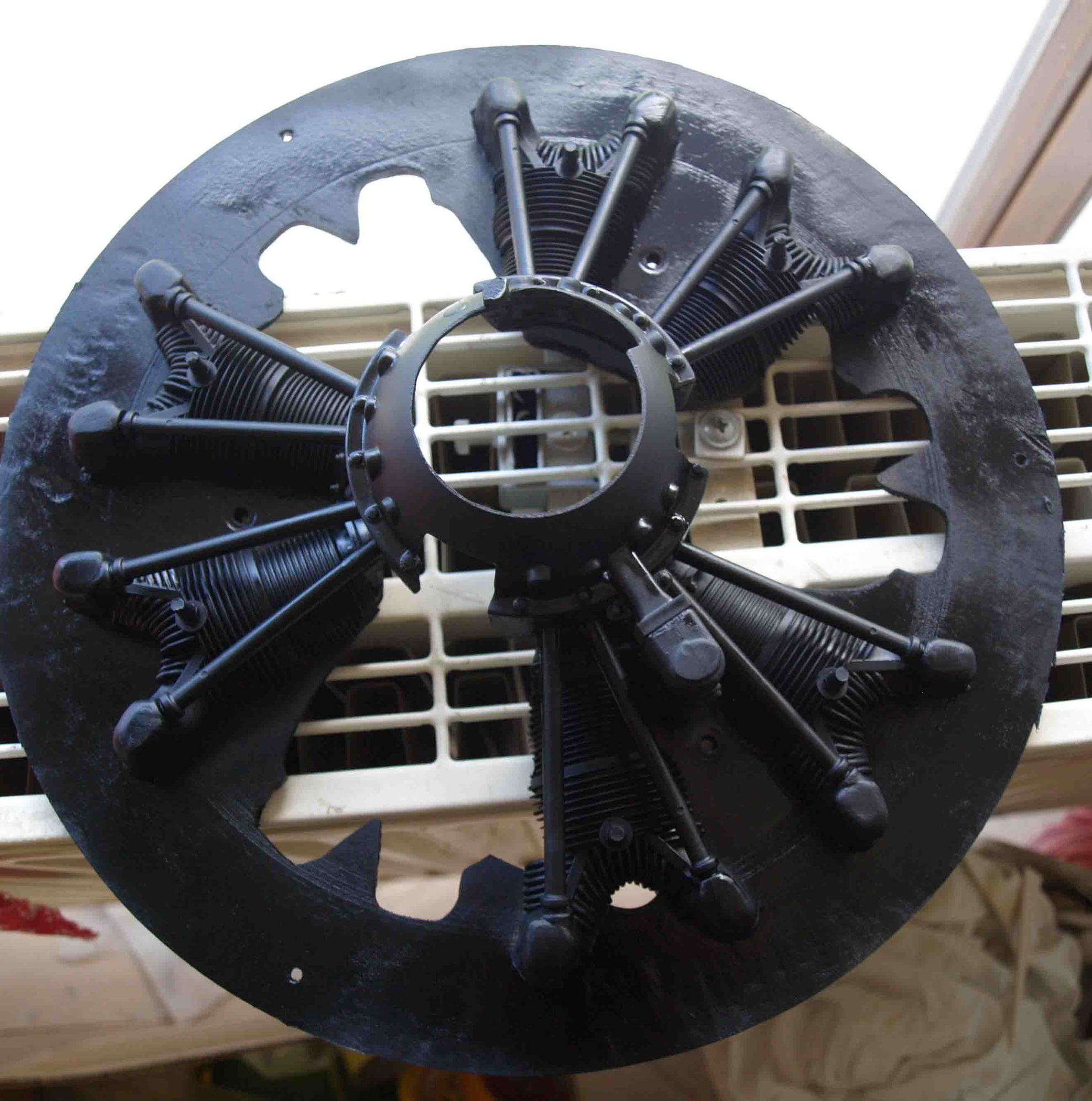
than I added the push rods
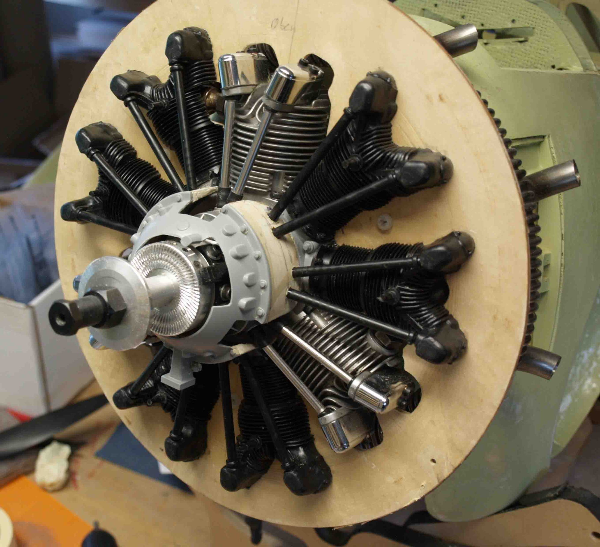
the whole thing was no black primered and the first layer of melallic colour is added.
I`hapy with the effect.

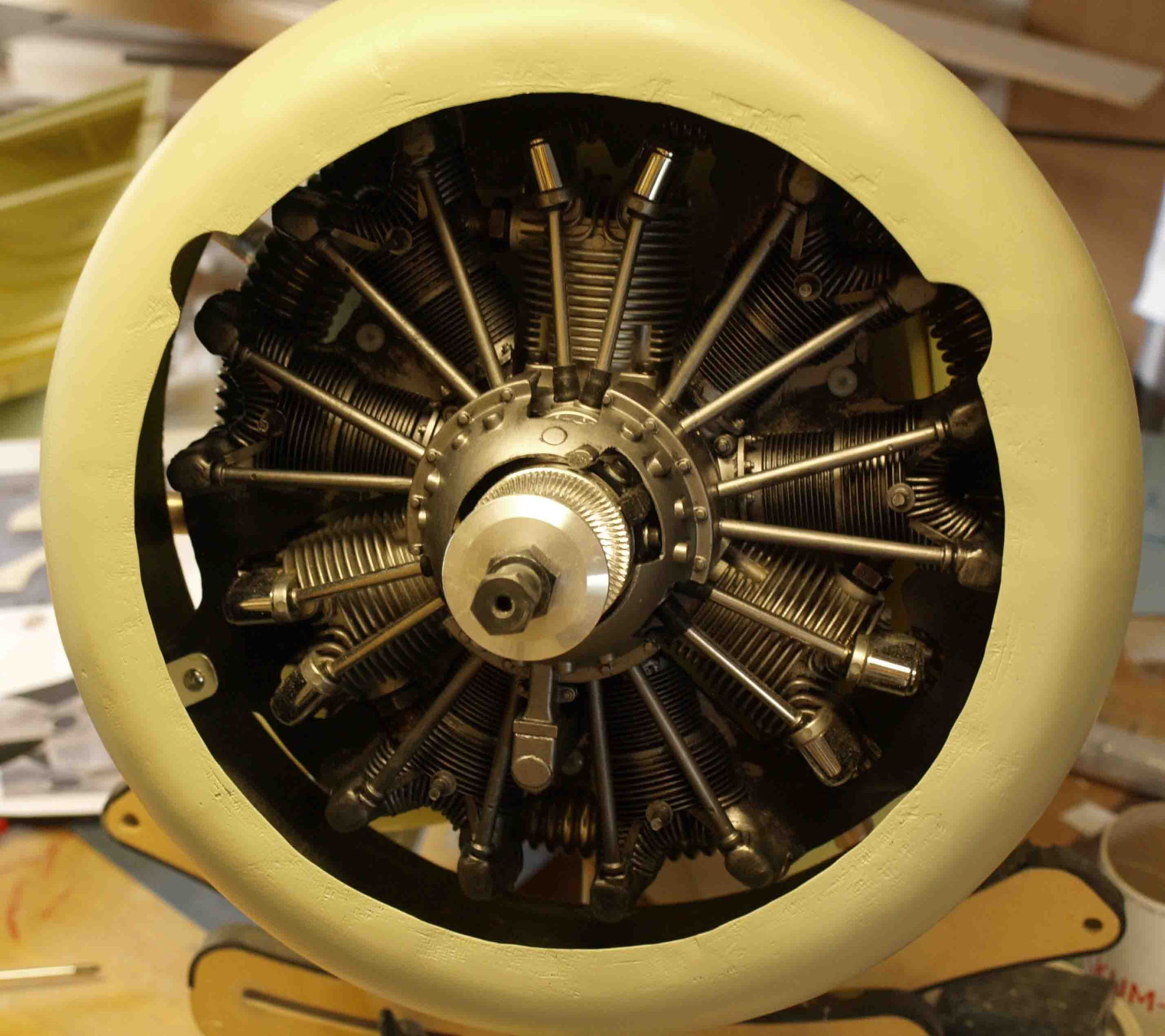
of course are many detail like sparks, cables and so on to do but I think it would be o.k. for the moment.
Then, I was searching the www and found a dummy-engine : https://modellstudio.de/epages/4ff94...oducts/6830800
This kit is not cheap but realy great, many details and the best thing of all: the diameter is close to my SAITO.
At first I had to optimize the chrankcase. Pictures says more than words
after preparing the zylinders
they were glued in place
than I added the push rods
the whole thing was no black primered and the first layer of melallic colour is added.
I`hapy with the effect.
of course are many detail like sparks, cables and so on to do but I think it would be o.k. for the moment.
Last edited by thomasmuckus; 09-22-2020 at 10:04 AM.
09-23-2020, 05:16 AM
#95
Thread Starter
Join Date: Jan 2014
Location: Eppendorf, Saxonia, Germany
Posts: 129
Likes: 0
Received 7 Likes
on
7 Posts
Thank you Mike
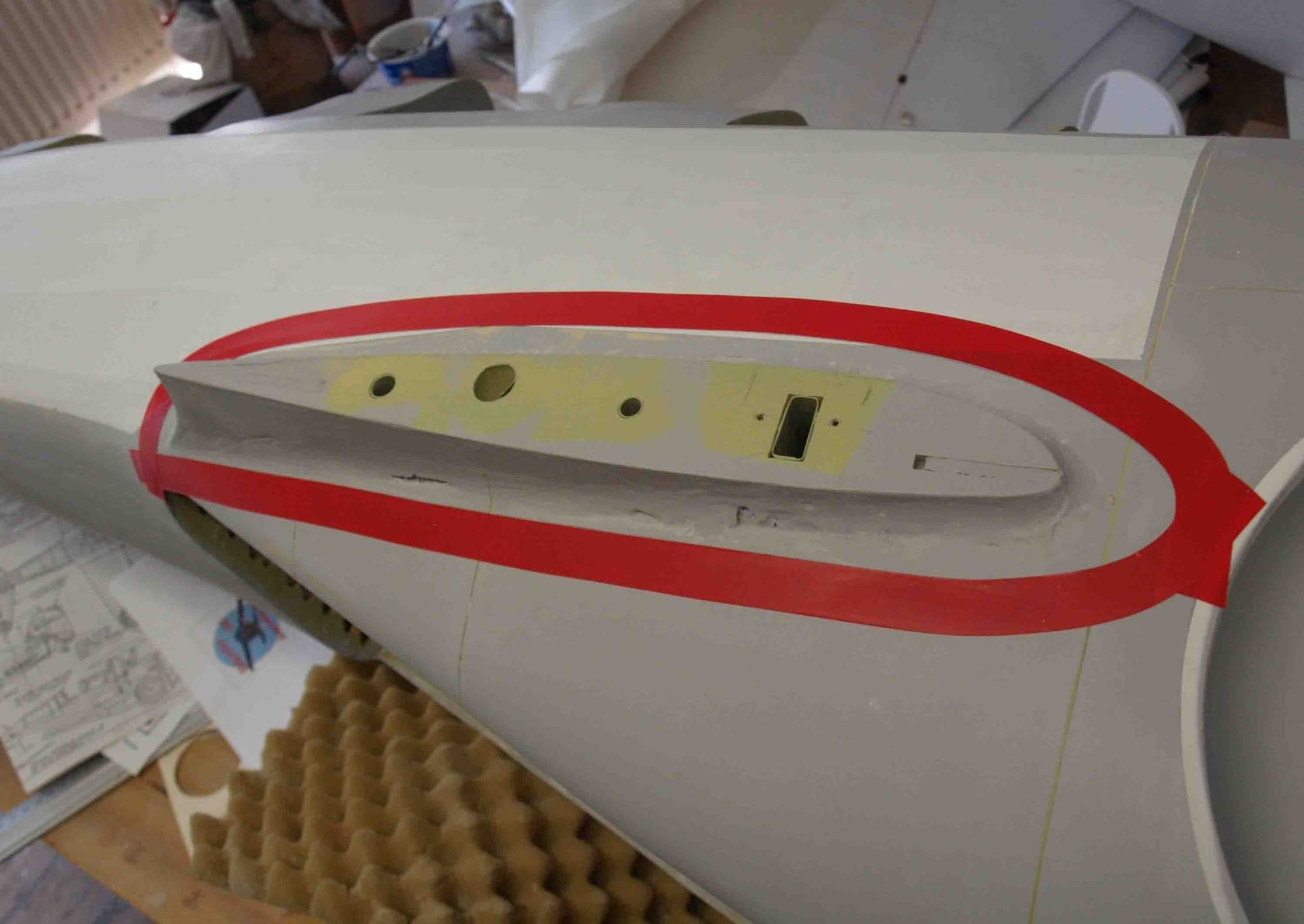
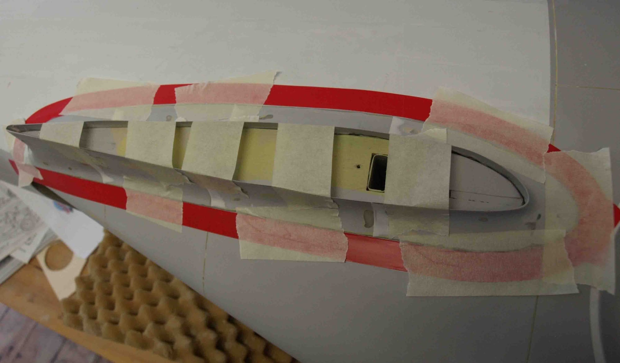
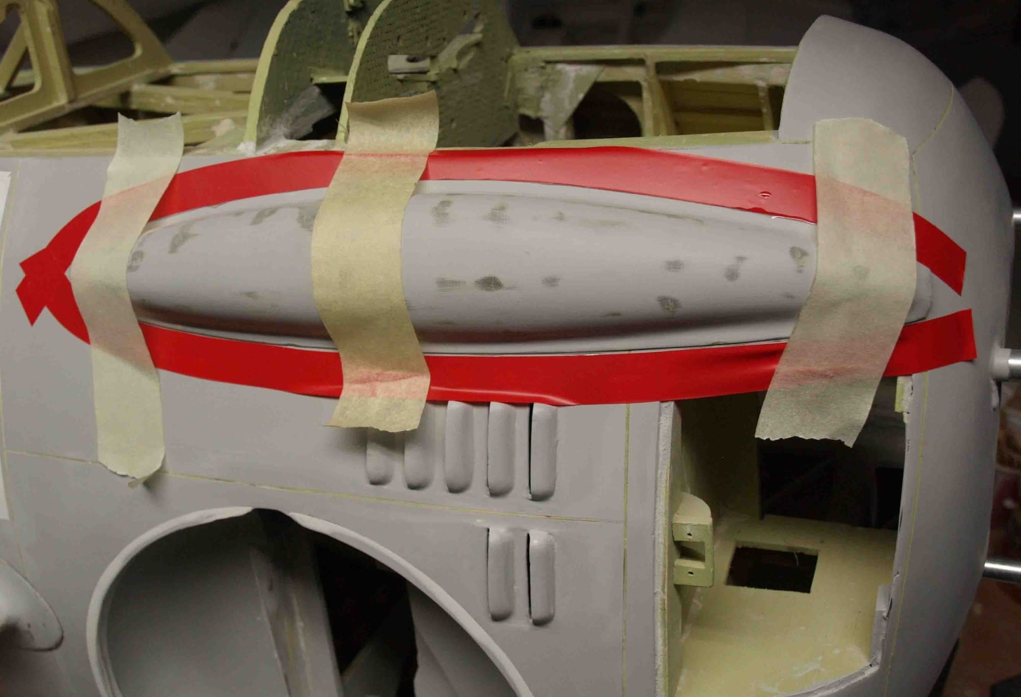
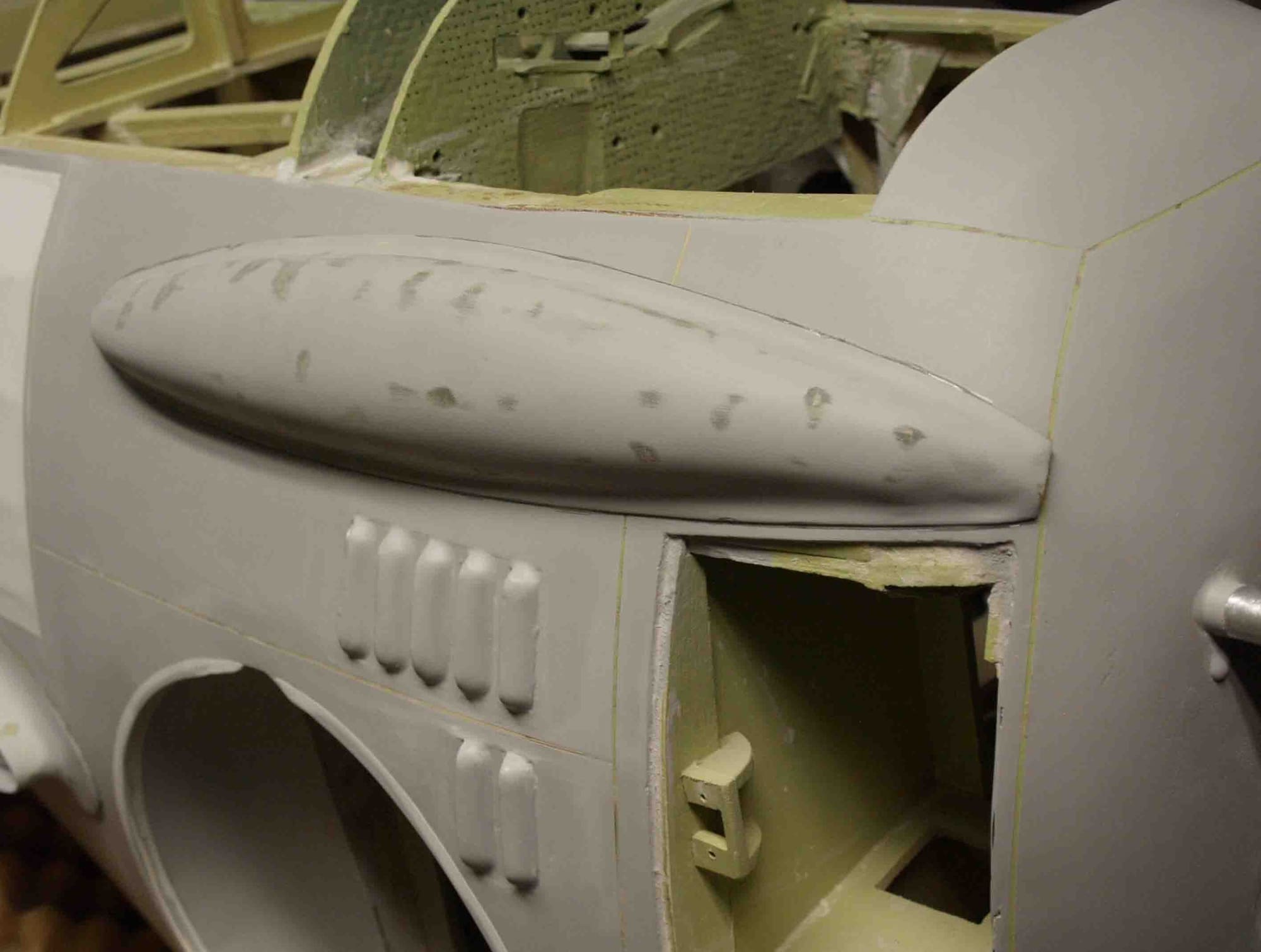
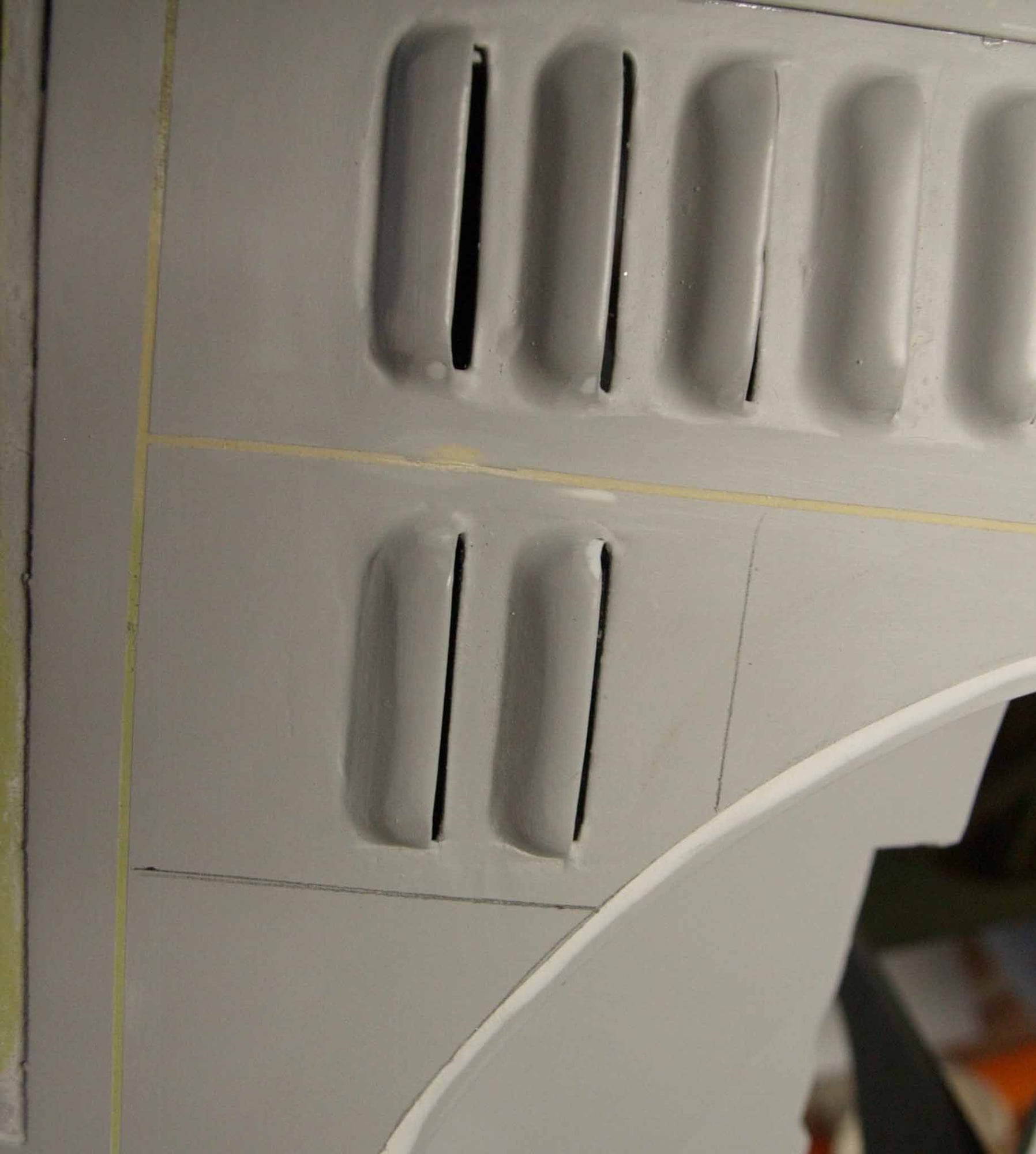
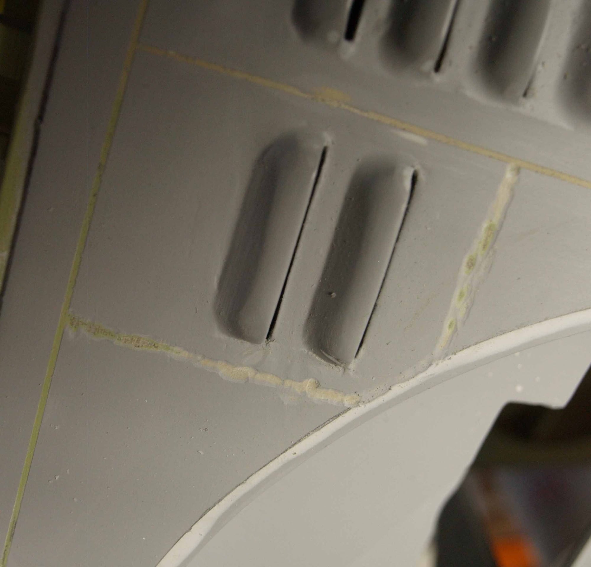
Now it`s time to makr the panels, service trapps etc.I use for tis some very masking tape, 0,75 mm wide. This is for the parts where some panels are next to next. If panels overlap I use an other technology.
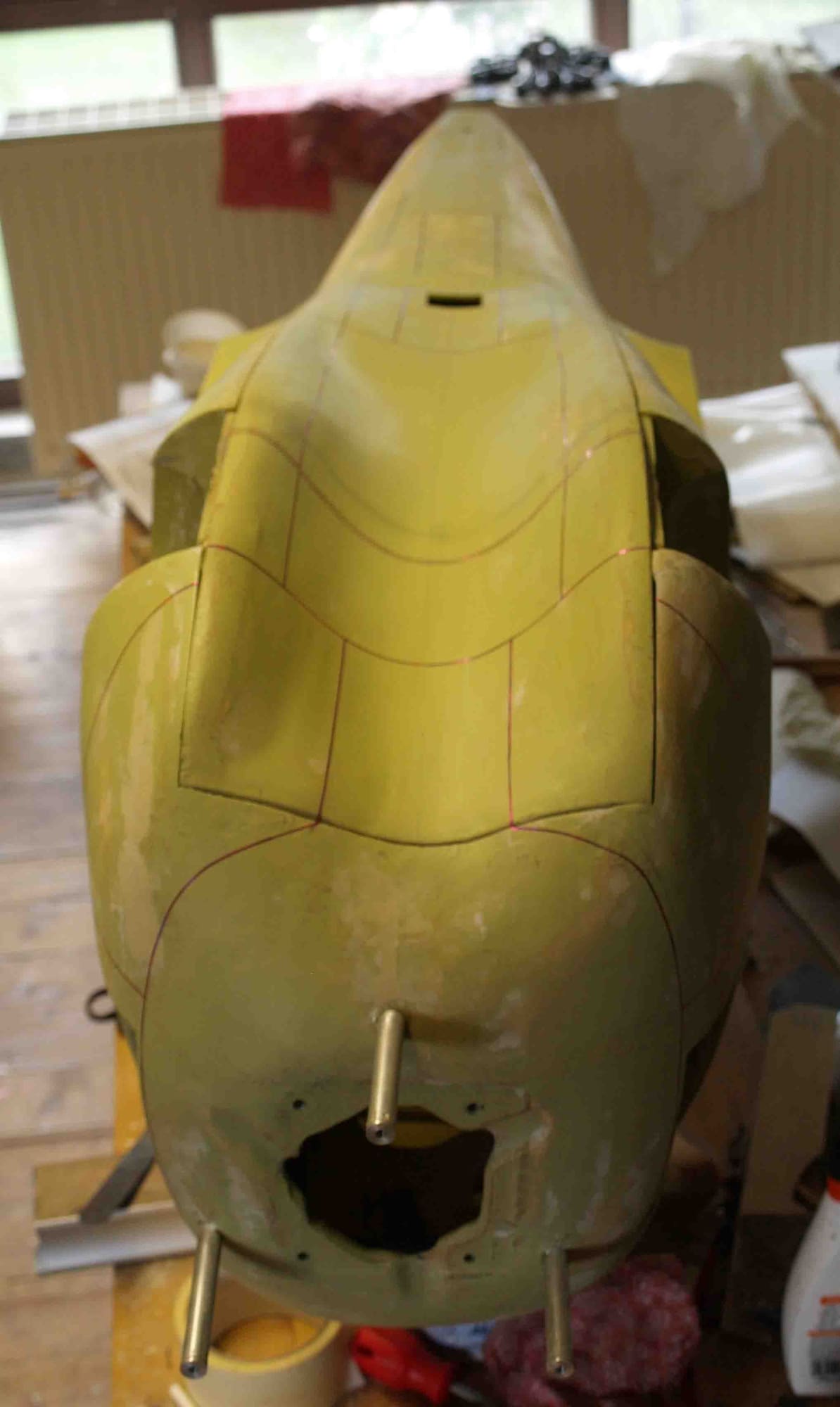
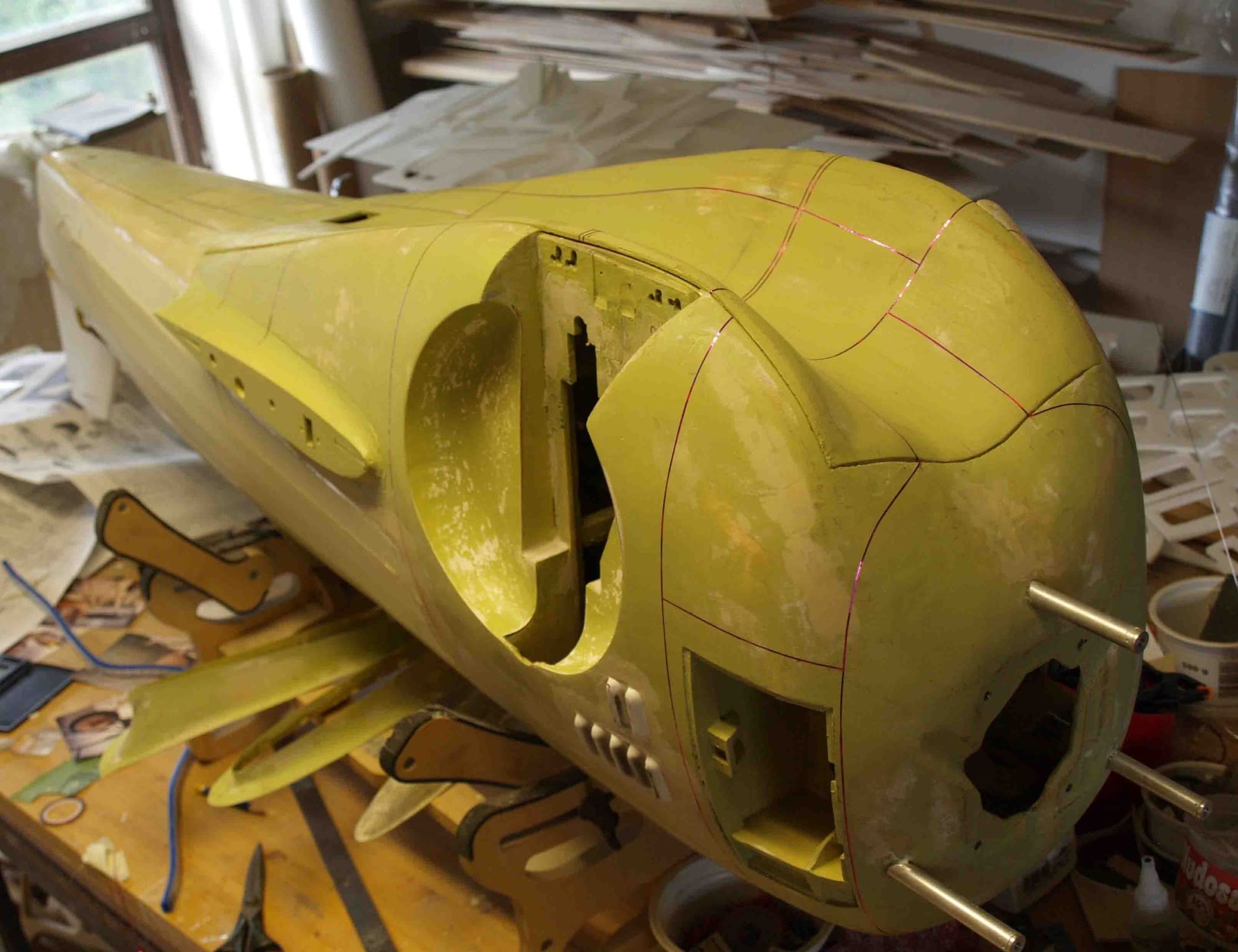
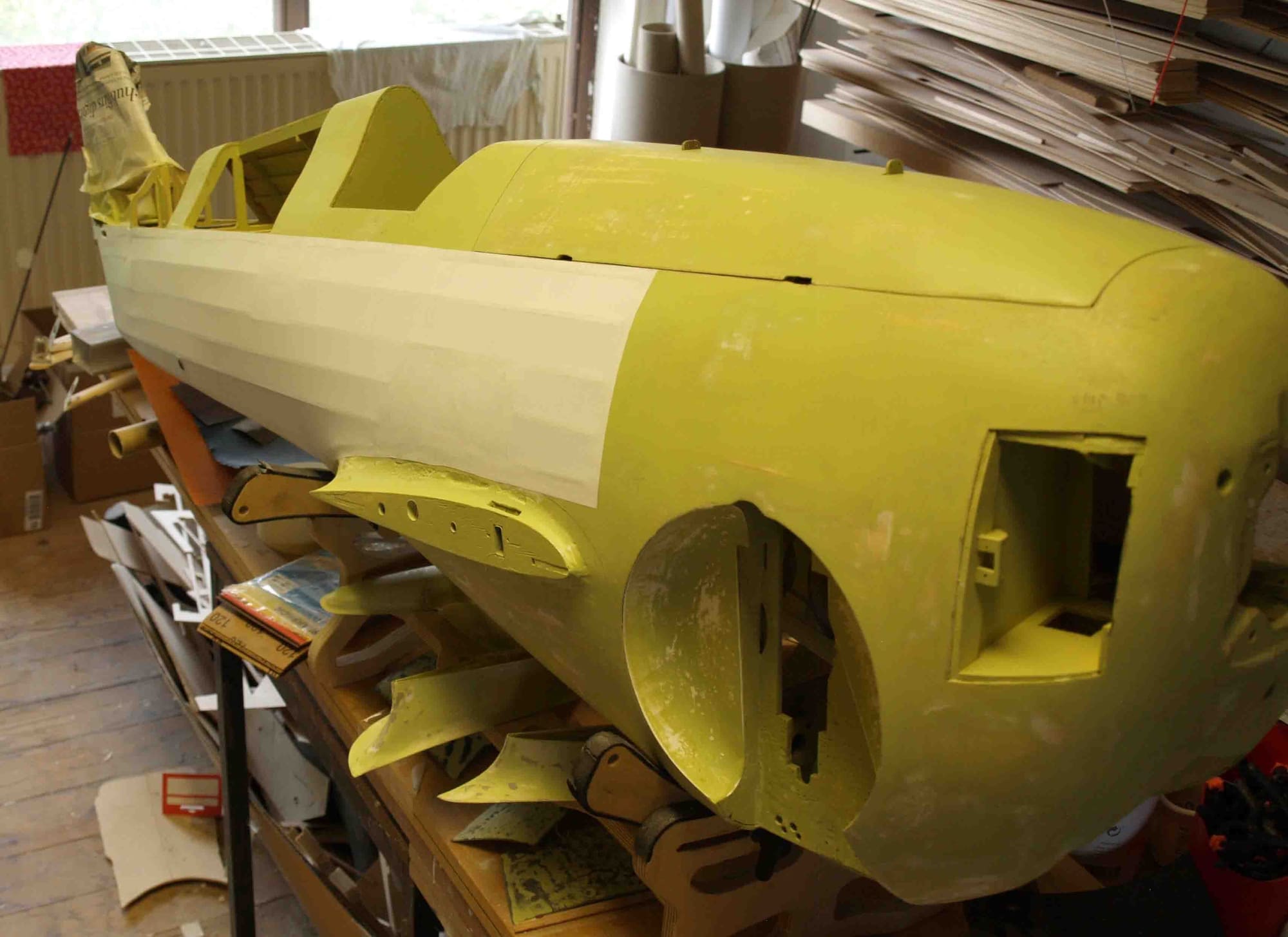
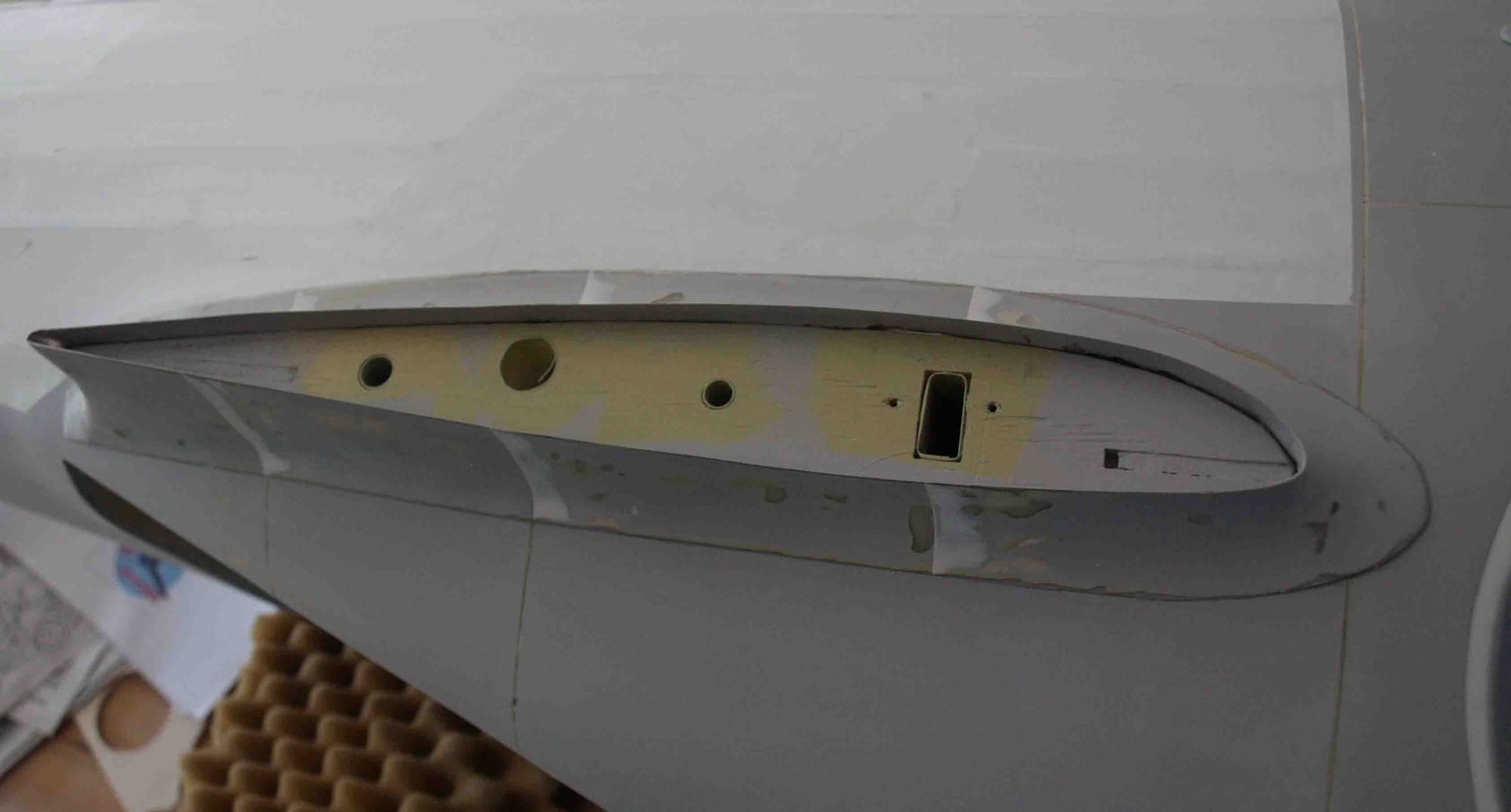
Then I sprayed the next layer filler-primer, water-sanding, sannding, sanding....
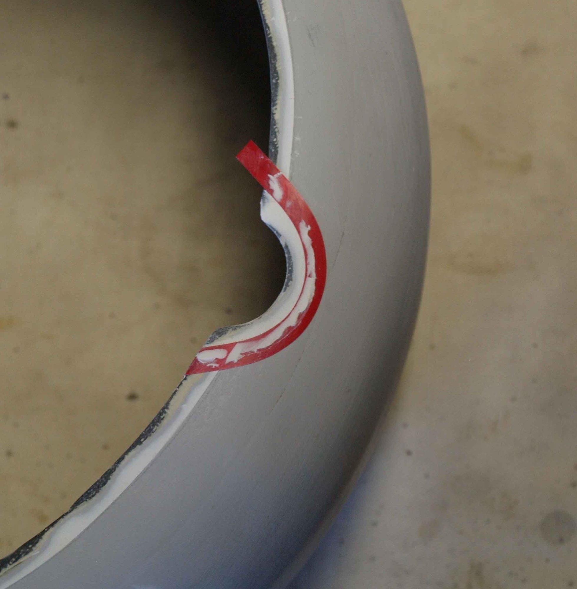
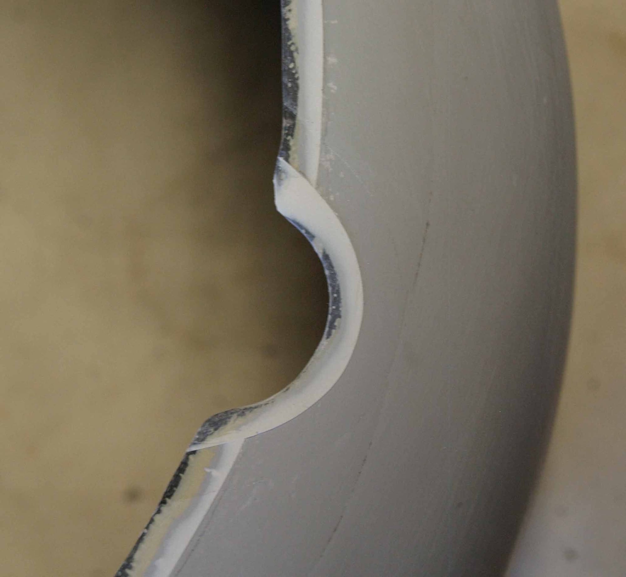
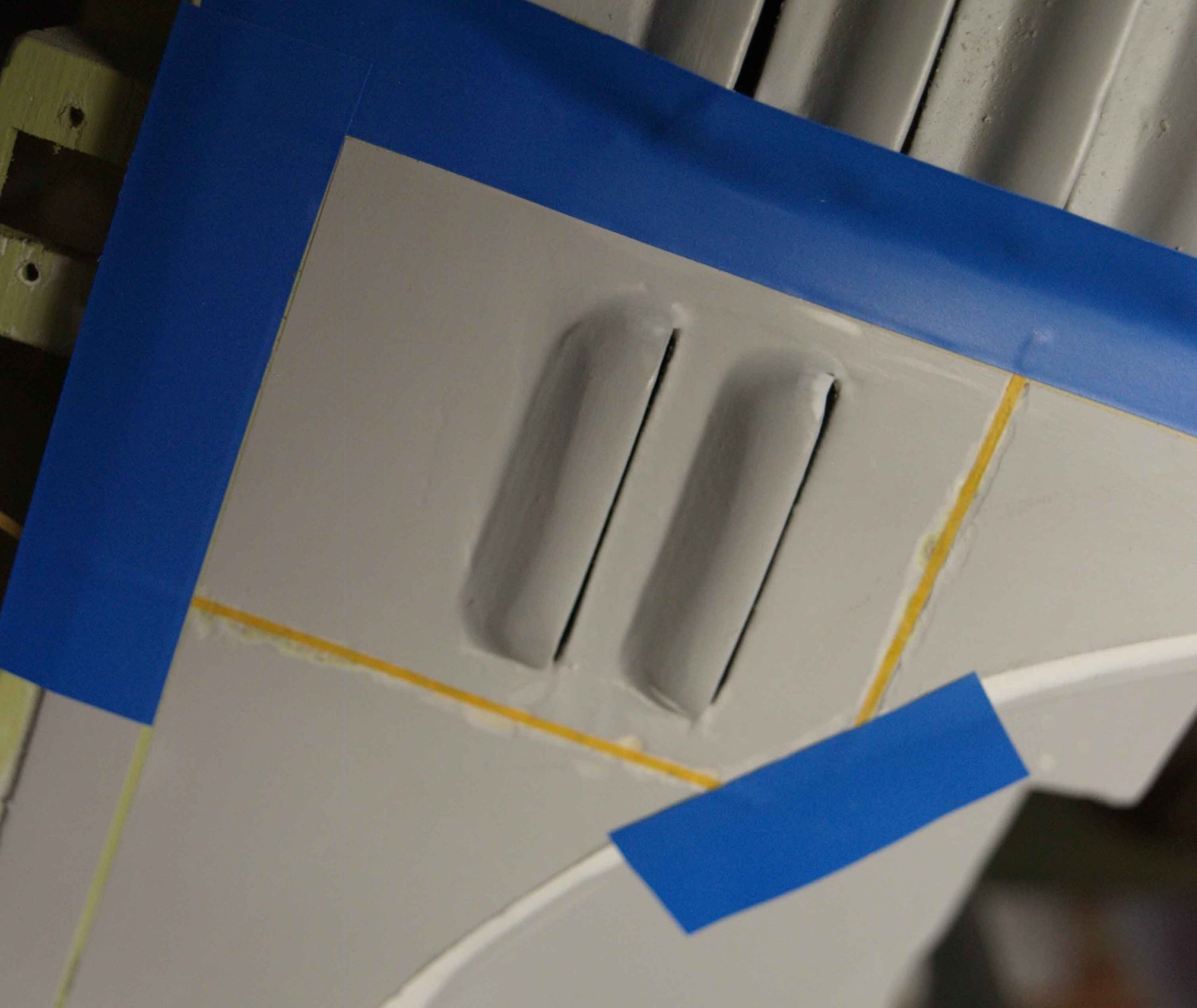
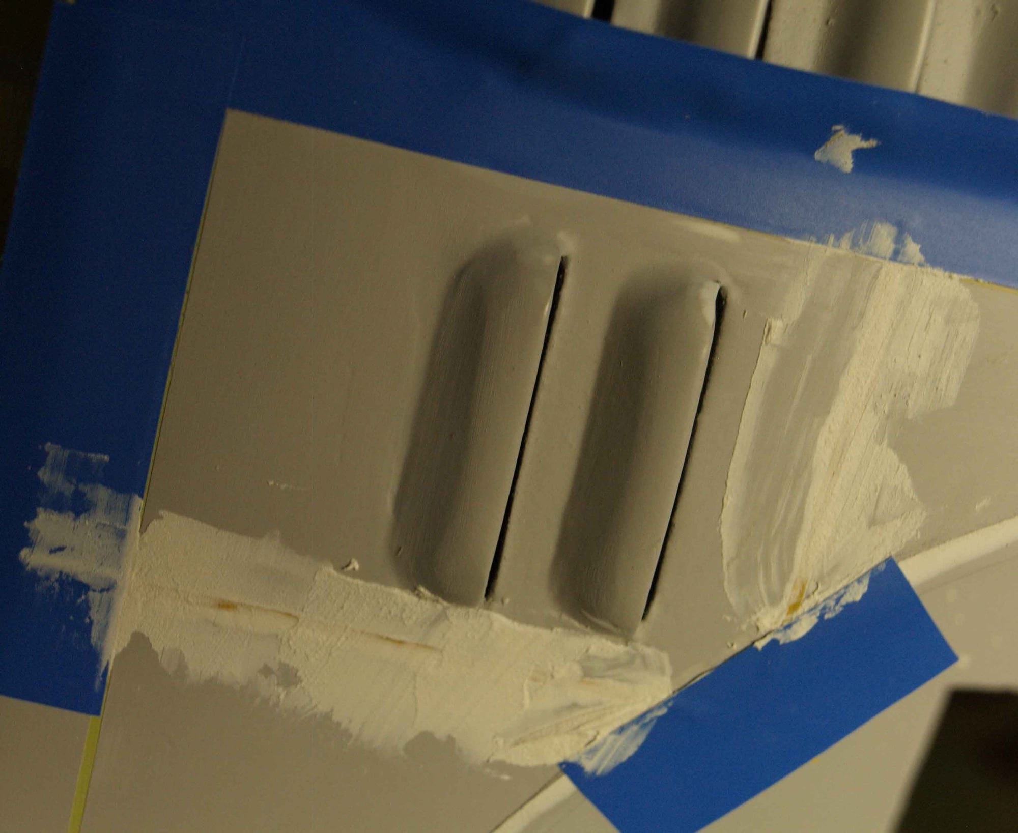
On the cowling a small edge overlaps. This edge I market with a thick masking tape and added a layer of putty. This was sanded down to the tape and so I had it.
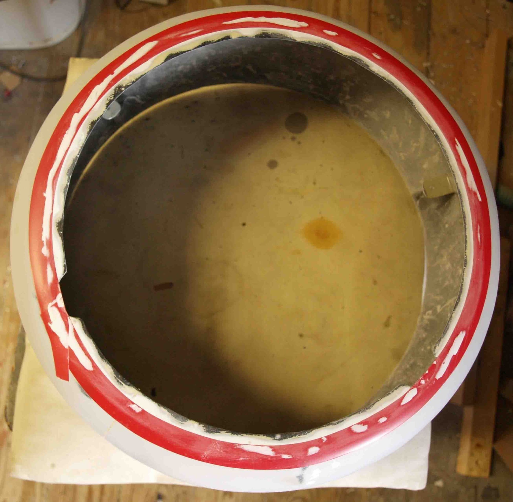
This technologie I used to all overlapping sheets.
Now it`s time to makr the panels, service trapps etc.I use for tis some very masking tape, 0,75 mm wide. This is for the parts where some panels are next to next. If panels overlap I use an other technology.
Then I sprayed the next layer filler-primer, water-sanding, sannding, sanding....
On the cowling a small edge overlaps. This edge I market with a thick masking tape and added a layer of putty. This was sanded down to the tape and so I had it.
This technologie I used to all overlapping sheets.
09-23-2020, 09:47 AM
#97
Thread Starter
Join Date: Jan 2014
Location: Eppendorf, Saxonia, Germany
Posts: 129
Likes: 0
Received 7 Likes
on
7 Posts
Detailing is going straight on here
So I added the wing fairings. To prevent that the glue spoils the wrong places, I masked the aera with masking tape.
Glued and fixed
finished. Here you can also see the overlaping panel sheets
In the same way I glued the gunblisters.
For control > a look from the front side, o.k. they are symmetrical.
The following users liked this post:
mgnostic (09-23-2020)
 09-24-2020, 01:52 AM
#100
Thread Starter
Join Date: Jan 2014
Location: Eppendorf, Saxonia, Germany
Posts: 129
Likes: 0
Received 7 Likes
on
7 Posts
thanks a lot, guys, thanks a lot.
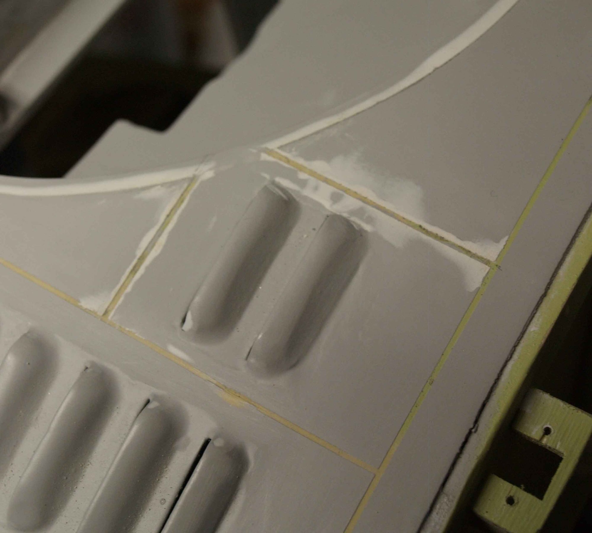
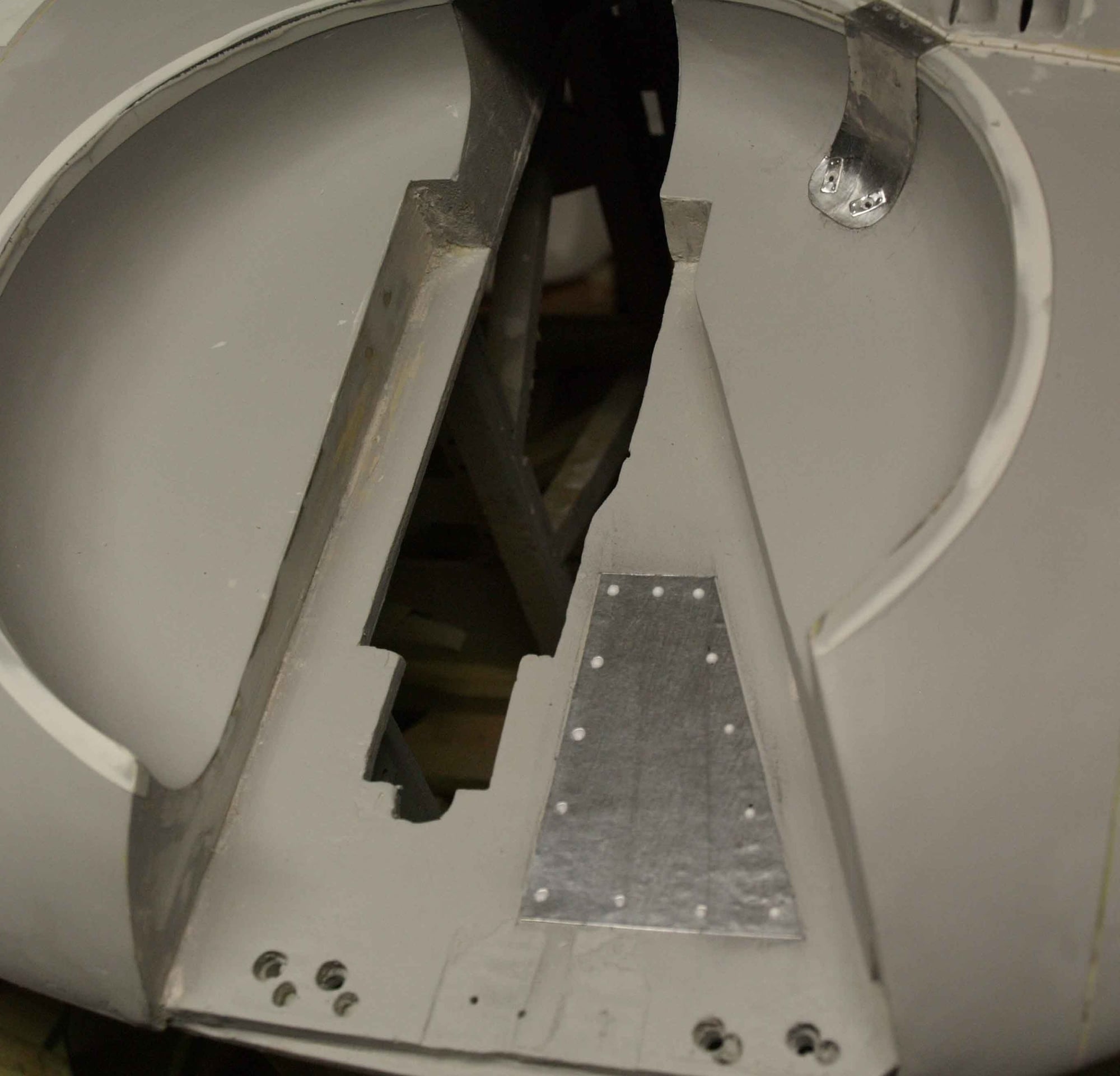
On the wheel arches Ialso added the overlaping sheets.
But then > desaster, I simply forgot to mark this. It looks so
So I had to mill of, marking with masking tape, putty and sanding.
On this airkraft are so many service trapps.
How to open, how to close? Of course, I would not make all of them work but it had to look so. Our copy shop staff cuttet me this of 0,15 mm Alu-sheet.
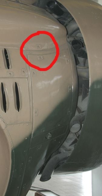
The rivets I`v made with a needle from the backside. On the pic above you can see the service trap into the wheel arches.
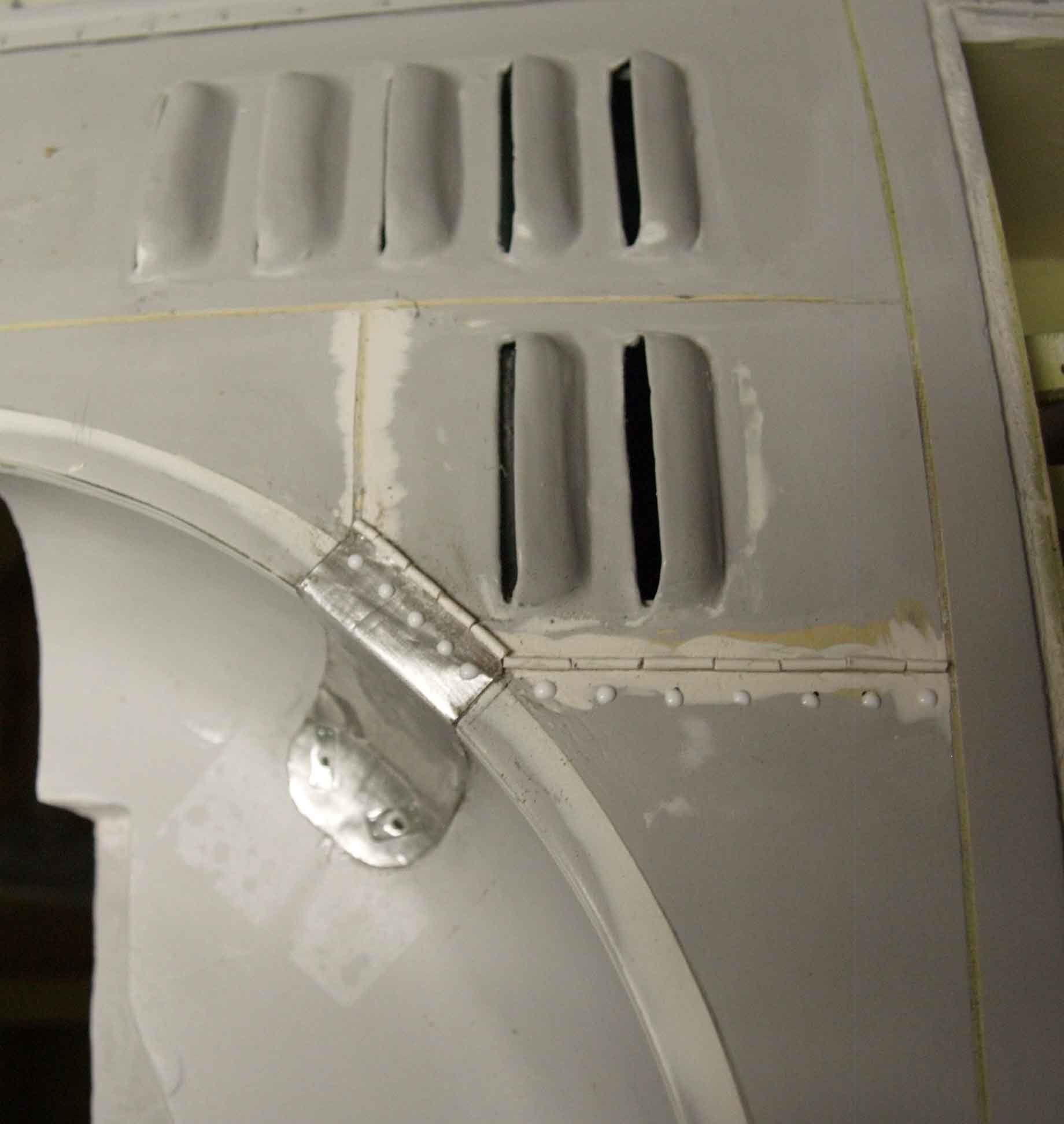
The rivet heads are made of a drop of "white glue". The hinge imitation is a 1 mm polystyrol wire.
the trap doors are made of 0,1 mm alu sheet. In this monent, I was faced to a decision > more detailing and may be it would notfly into the next two years, or, back to the roots (semi scale) and stop excessive detailing...... Rivets I will do but I`m thinking about cockpit, I think it would be a "bust-cockpit" not a complete one. The last complete cockpit took me more than six months...
Currently I`m i a Rehab facility so I can take time to decide. The thread is now up to date, we look ahead.
On the wheel arches Ialso added the overlaping sheets.
But then > desaster, I simply forgot to mark this. It looks so
So I had to mill of, marking with masking tape, putty and sanding.
On this airkraft are so many service trapps.
How to open, how to close? Of course, I would not make all of them work but it had to look so. Our copy shop staff cuttet me this of 0,15 mm Alu-sheet.
The rivets I`v made with a needle from the backside. On the pic above you can see the service trap into the wheel arches.
The rivet heads are made of a drop of "white glue". The hinge imitation is a 1 mm polystyrol wire.
the trap doors are made of 0,1 mm alu sheet. In this monent, I was faced to a decision > more detailing and may be it would notfly into the next two years, or, back to the roots (semi scale) and stop excessive detailing...... Rivets I will do but I`m thinking about cockpit, I think it would be a "bust-cockpit" not a complete one. The last complete cockpit took me more than six months...
Currently I`m i a Rehab facility so I can take time to decide. The thread is now up to date, we look ahead.
Last edited by thomasmuckus; 09-24-2020 at 02:02 AM.