


Pilatus PC9 1/3 scale
 05-08-2010, 03:29 PM
#26

Thread Starter

Join Date: Aug 2009
Location: Paris, FRANCE
Posts: 143
Likes: 0
Received 0 Likes
on
0 Posts
You've seen the principle now it is time to do the same forrest of the bottom half ....
The following formers were aligned and then glued in place then wecut a small section of the central wing to measure the wing angle.

So far everything seems okay, but the foam is not rigid enough to be absolutely sure.

In this picture we can see that all formers are resting on the length of the wing.
Then we have to cover up the wing tip to mesure correctly the angle... next time for a new stage of construction.
 05-16-2010, 04:13 AM
#27
Thread Starter
Join Date: Aug 2009
Location: Paris, FRANCE
Posts: 143
Likes: 0
Received 0 Likes
on
0 Posts
Work is progressing slowly but surely.

The area of the location of the wing has been achieved through the patterns of the wing and the cutting wire.
The base of the wing is perfect and the incidence has been controled.
Note that the wingtip has been shuttered for ensuring rigidity when measuring the angle.

Note that the wingtip has been shuttered for ensuring rigidity when measuring the angle.
Same result but without the piece of wing.
Another work of the day was a big work on the nose of the aircraft, a very large amount of filler was added because the shape was not good.

We would have to go about it differently, by cutting a piece of foam and gluing a square block that would have been re-sanded, it would have saved us a lot of time. We'll know for next time.
We would have to go about it differently, by cutting a piece of foam and gluing a square block that would have been re-sanded, it would have saved us a lot of time. We'll know for next time.
05-24-2010, 02:15 PM
#28
Thread Starter
Join Date: Aug 2009
Location: Paris, FRANCE
Posts: 143
Likes: 0
Received 0 Likes
on
0 Posts
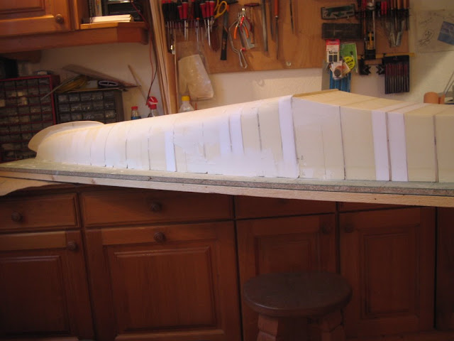
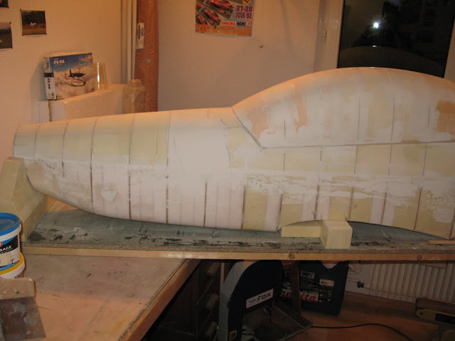
This technique remains the same for further work, we repeat process until reaching the rear of the fuselage.

Here a delicate area of processing soft shape between square at the rear of the wing to the round fuselage.
The cut was made on Hotwire between formers it will of course be sand.
Also the front is better but needs more work.

The black lines enable us to know what area should be recharged of mastic.
The technique is simple, with a 5mm bucket, by applying on the form, we see immediately is missing material.

Viewed of the air intake that feeds the turbo-prop of the PC9. It will be very useful to cool our cylinders.
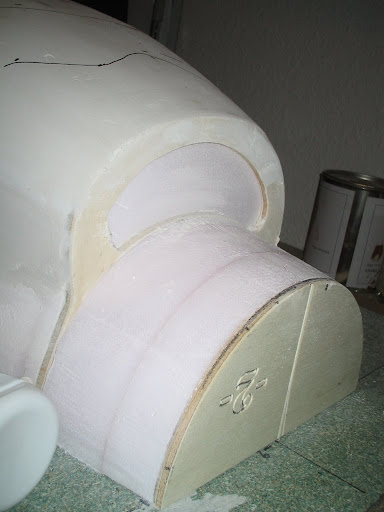
Always the front and bottom of the fuselage. On the front of the lip of the intake will be added a block that will be formatted to give the right angle.
Viewed of the air intake that feeds the turbo-prop of the PC9. It will be very useful to cool our cylinders.
Always the front and bottom of the fuselage. On the front of the lip of the intake will be added a block that will be formatted to give the right angle.
05-30-2010, 01:59 AM
#29
Thread Starter
Join Date: Aug 2009
Location: Paris, FRANCE
Posts: 143
Likes: 0
Received 0 Likes
on
0 Posts
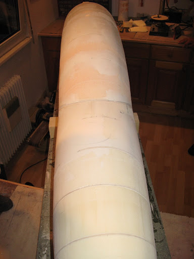
The same process is repeated until this:

The transition area from a square to a round section slowly starting to look like something

A quick overview of the fuselage:
And with the portion of the wing in place.

With a good amount of time of sanding, everything should be clean and smooth.
The transition area from a square to a round section slowly starting to look like something
A quick overview of the fuselage:
And with the portion of the wing in place.
With a good amount of time of sanding, everything should be clean and smooth.
06-05-2010, 03:37 PM
#30
Thread Starter
Join Date: Aug 2009
Location: Paris, FRANCE
Posts: 143
Likes: 0
Received 0 Likes
on
0 Posts
Then follows the end of the fuselage.

Cutting the central spur and two rump pieces

View of the rump

Some fittings with filler on the back.

The spur is 1cm thick.
Cutting the central spur and two rump pieces
View of the rump
Some fittings with filler on the back.
The spur is 1cm thick.
06-07-2010, 04:13 PM
#31


Join Date: Sep 2005
Location: Mesa, AZ
Posts: 1,456
Likes: 0
Received 0 Likes
on
0 Posts
Nice work!!! I start plan for a Italian and he skipped when I sent him a detailed set of three views. I have the mechnical detailes figured out for the hatch / gear links if you are interested would gladly share them with you!
06-13-2010, 01:07 AM
#33
Thread Starter
Join Date: Aug 2009
Location: Paris, FRANCE
Posts: 143
Likes: 0
Received 0 Likes
on
0 Posts
That tail is sanded, and the rear starts to be righter with a good dose of putty.
Focus on the rump

There is still a lot of sanding and putty before arriving at a correct shape

Focus on the rump
There is still a lot of sanding and putty before arriving at a correct shape
06-13-2010, 11:03 AM
#34
Join Date: Sep 2005
Location: Mesa, AZ
Posts: 1,456
Likes: 0
Received 0 Likes
on
0 Posts
06-19-2010, 06:25 AM
#35
Thread Starter
Join Date: Aug 2009
Location: Paris, FRANCE
Posts: 143
Likes: 0
Received 0 Likes
on
0 Posts
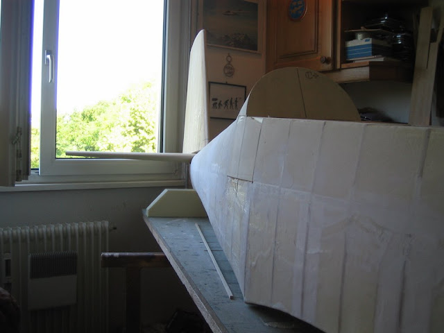
The lower part is almost over we position the right angle on the air intake.

With a good dose of putty to get the correct shape
Viewed from a slightly higher, symmetry looks to be respected.

On the back, we stuck up the spur, and after many sessions of putty shapes begin to be harmonious.

This is another view to see that the line begins to be respected.
Even if this image is not a good quality we can better seen the entrance of air to fuel the engine even at high angles like for take off.

Next step is fiberglass and resin, before to remove the bottom part from the worktable.
With a good dose of putty to get the correct shape
Viewed from a slightly higher, symmetry looks to be respected.
On the back, we stuck up the spur, and after many sessions of putty shapes begin to be harmonious.
This is another view to see that the line begins to be respected.
Even if this image is not a good quality we can better seen the entrance of air to fuel the engine even at high angles like for take off.
Next step is fiberglass and resin, before to remove the bottom part from the worktable.
06-27-2010, 05:49 PM
#37
Thread Starter
Join Date: Aug 2009
Location: Paris, FRANCE
Posts: 143
Likes: 0
Received 0 Likes
on
0 Posts
Thanx,
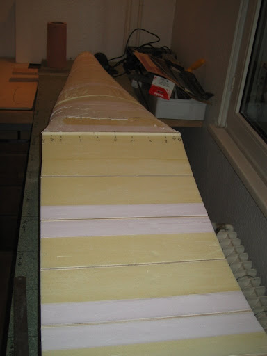
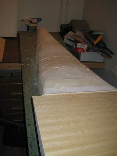
Last step before "unmold" from the table, we fiber the shape.

Last step before "unmold" from the table, we fiber the shape.
Cutting the fiber twill 80g/dm2 two layers will be needed to maintain the bottom.
Rear section with the fiber and resin

Half lower belly fully fiber glassed

Front part glassed
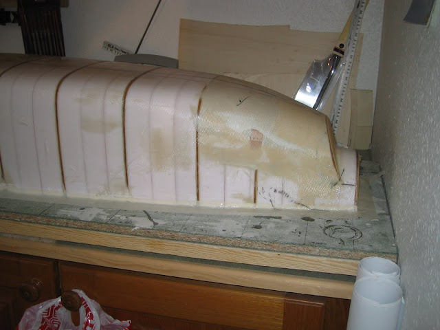
The next step will be to cut down the bottom half from the work plan.
Half lower belly fully fiber glassed
Front part glassed
The next step will be to cut down the bottom half from the work plan.

 07-03-2010, 12:09 PM
#42
Thread Starter
Join Date: Aug 2009
Location: Paris, FRANCE
Posts: 143
Likes: 0
Received 0 Likes
on
0 Posts
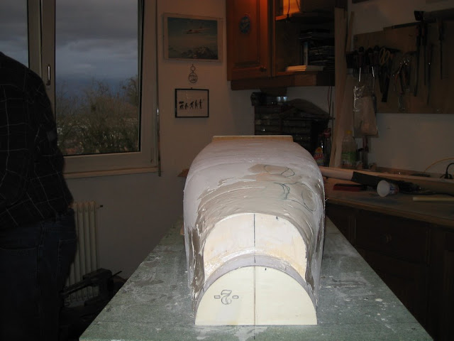
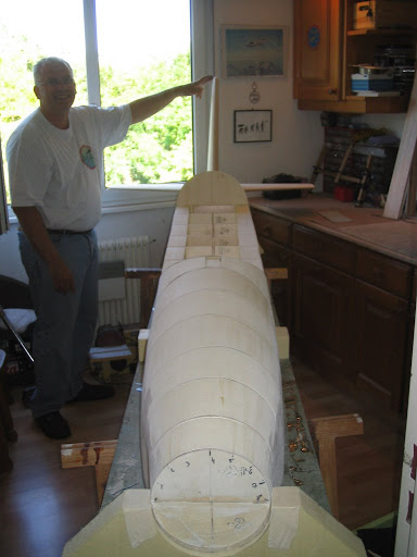
This time it is removed from the workbench ...
Thanks to Christian and his son Jean for this work which has not been very easy

We therefore take this opportunity to make a cradle that nothing happens for the rest of the building.

Thank you to Jean-Claude that came to Christian's house to cut with hot wire the cardle.
In the photo below you can see how much we failed the fiber from the bottom, there are a lot of folds ... and how much time of work to catch up with all that eh Christian???

That day's work is finished, the supports are cut and pasted the same board that serves as our work plan.

This looks like the hull of a sailboat at this stage rather than a plane, we'd gone wrong????
A last one to show the supports gluing with the lower half in place. Seals are used to effectively apply during the drying time.

The next step will be interesting with the assembly of the upper half.
We therefore take this opportunity to make a cradle that nothing happens for the rest of the building.
Thank you to Jean-Claude that came to Christian's house to cut with hot wire the cardle.
In the photo below you can see how much we failed the fiber from the bottom, there are a lot of folds ... and how much time of work to catch up with all that eh Christian???
That day's work is finished, the supports are cut and pasted the same board that serves as our work plan.
This looks like the hull of a sailboat at this stage rather than a plane, we'd gone wrong????
A last one to show the supports gluing with the lower half in place. Seals are used to effectively apply during the drying time.
The next step will be interesting with the assembly of the upper half.
07-10-2010, 07:06 AM
#45
Thread Starter
Join Date: Aug 2009
Location: Paris, FRANCE
Posts: 143
Likes: 0
Received 0 Likes
on
0 Posts
Absolutely incredible feat, Christian made a huge step forward during this week ...

And yes it has almost finished the top in one week ... impressive.

After applying putty and sanding, everything will be at the same level there will be no difference between the fibered part (down) and the non-fibered part (top).

And yes it has almost finished the top in one week ... impressive.
Side view.
To go faster, Christian has tested a new way of working:
He glues few blocks of foam and then cut it with the hot wire, building on the formers then he sand the rest. This technique allows to work very quickly and make a minimum of dust.

Front part with the inclined former of the cockpit.After an afternoon of work, all the remaining blocks are cut and sanded, we added the inclined parts at the front and the rear of the cockpit.
We put the rudder and stab for fun, happy of the result.

Another angleviewof the rear fuselage. Now it looks like an airplane.After applying putty and sanding, everything will be at the same level there will be no difference between the fibered part (down) and the non-fibered part (top).
After a first layer of putty to fill the holes.
We will have to wait until it dries to sand it and to make a second layer of an other putty easier to sand.
07-10-2010, 04:19 PM
#47
Thread Starter
Join Date: Aug 2009
Location: Paris, FRANCE
Posts: 143
Likes: 0
Received 0 Likes
on
0 Posts
Well I would really like to have her with the turboprop, but for now we have choosen the bicylinder in line 140cc.
May be one day the turboprop will come on her.
May be one day the turboprop will come on her.
07-18-2010, 04:19 PM
#49
Thread Starter
Join Date: Aug 2009
Location: Paris, FRANCE
Posts: 143
Likes: 0
Received 0 Likes
on
0 Posts
For now we just made a false exhaust in fiberglass that we want to be unmountable. I have no idea yet of the real exhaust on the model.

three weeks later, the bubble is well advanced, it has a beautiful curve, and looks good with the rear of the fuselage which was been rebuilt elsewhere.
three weeks later, the bubble is well advanced, it has a beautiful curve, and looks good with the rear of the fuselage which was been rebuilt elsewhere.
Front part of the fuselage the cockpit on it.Forward fuselage and on the bubble.
On the bubble the same technique as the fuselage was used.
A plan was made and then the formers have been put on the plane, and then we filled between each pair of formers.
top view.

The rear of the fuselage with Christian who takes up the rudder.

Side view of the volume is impressive.
top view.
The rear of the fuselage with Christian who takes up the rudder.
Side view of the volume is impressive.