


Pulse 125 - Swapping out the DLE 20 for an RCGF 32
 10-07-2013, 05:16 AM
#1
Senior Member
Thread Starter

I've had the Pulse flying with the DLE 20 for a couple of years now but the engine just isn't quite powerful enough to make the plane do what I want it to do. I came across a good deal on an RCGF 32 a few weeks ago and that's going in. The DLE 20 will go to my first plane - the Hobbistar 60 trainer, now a tail dragger - but that's another story for another thread and will come later. It should be a fun winter.
To the shop!
One last look at the DLE 20...

... and out it comes.

Got to fill the old mounting holes...

... and drill the new ones.


Time for a test fit. Bolts in.

Standoffs on.

Test mount complete.

Drive washer should be 140 mm from the firewall. Ruh roh. Looks like I'm going to need some shorter standoffs...

... because this don't look right at all.


I found a couple that will work - both 38mm (I need 42mm - will just need to add a couple of washers):
Evolution

PSP

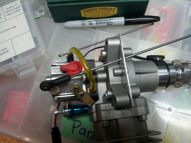
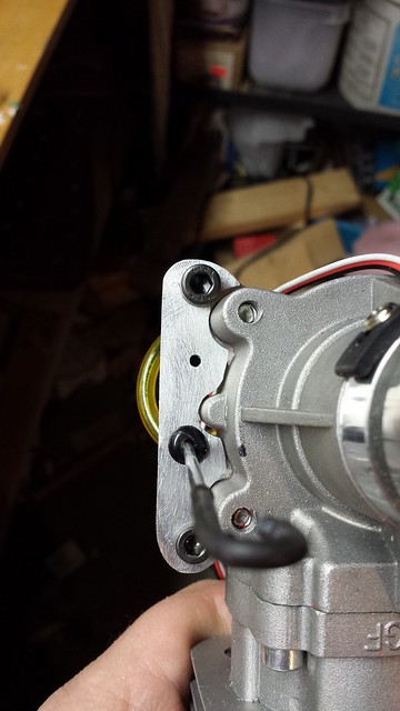
During the test fit I noticed that the throttle and choke levers are on the starboard side, not the bottom like they used to be. Now I have to re-work the linkages. All part of the fun.
The RCGF will get the same treatment as the DLE 20 got:
To the shop!
One last look at the DLE 20...
... and out it comes.
Got to fill the old mounting holes...
... and drill the new ones.
Time for a test fit. Bolts in.
Standoffs on.
Test mount complete.
Drive washer should be 140 mm from the firewall. Ruh roh. Looks like I'm going to need some shorter standoffs...
... because this don't look right at all.
I found a couple that will work - both 38mm (I need 42mm - will just need to add a couple of washers):
Evolution
PSP
During the test fit I noticed that the throttle and choke levers are on the starboard side, not the bottom like they used to be. Now I have to re-work the linkages. All part of the fun.
The RCGF will get the same treatment as the DLE 20 got:
 10-07-2013, 05:16 AM
#2
Senior Member
Thread Starter
The reed valve block was a mess - rough surfaces and a lots of casting flash in the ports:
Before:


After:


Installed the Bowman ring too. Here's the sloppy old one:

And the nice new one:

I'm working on the carb equalization now.
Before:
After:
Installed the Bowman ring too. Here's the sloppy old one:
And the nice new one:
I'm working on the carb equalization now.
10-07-2013, 05:17 AM
#3
Senior Member
Thread Starter
Moving on... ")
To get the RCGF 32's drive washer 140mm forward of the firewall per the Pulse 125's specs, I need 42mm standoffs. However, the rear of the carb is about 62mm behind the mounting point on the engine. I'm going to have to cut into the firewall and to access the HS and LS needles I'll have to drill through the side of the firewall and fuselage.
Here's a little story stick to represent how much further back the engine needs to go.
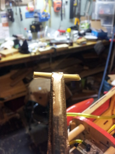
Here it is with the needles.
And here's the rough cut pattern.
To get the RCGF 32's drive washer 140mm forward of the firewall per the Pulse 125's specs, I need 42mm standoffs. However, the rear of the carb is about 62mm behind the mounting point on the engine. I'm going to have to cut into the firewall and to access the HS and LS needles I'll have to drill through the side of the firewall and fuselage.
Here's a little story stick to represent how much further back the engine needs to go.
Here it is with the needles.
And here's the rough cut pattern.
10-07-2013, 05:17 AM
#4
Senior Member
Thread Starter
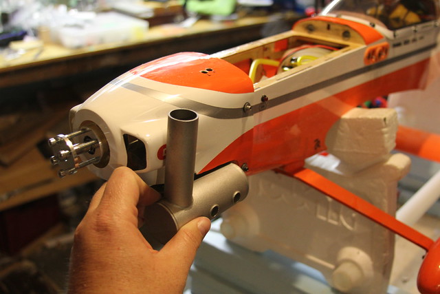
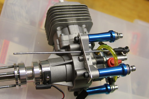
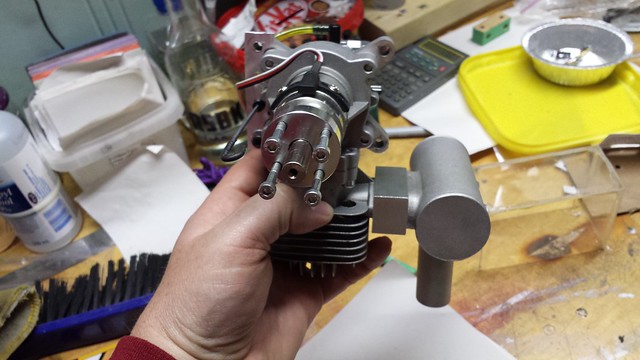
Firewall is cut and engine is on, at least for the time being.


I'll have to work out the choke linkage and move the throttle servo but it looks good so far. Cowl fits too!

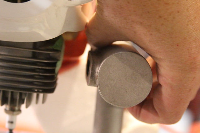
Then came the ruh roh moment. Muffler doesn't fit.
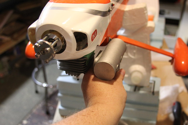
I could hack a chunk out of the fuse or turn it upside down (downside up?)
But I think I am going to fab a spacer instead.
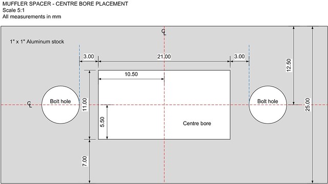
20mm will do it. And the face will need to look like this:
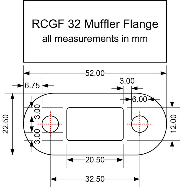
If I go with a spacer I'll use aluminum.
I'll have to work out the choke linkage and move the throttle servo but it looks good so far. Cowl fits too!
Then came the ruh roh moment. Muffler doesn't fit.
I could hack a chunk out of the fuse or turn it upside down (downside up?)
But I think I am going to fab a spacer instead.
20mm will do it. And the face will need to look like this:
If I go with a spacer I'll use aluminum.
10-07-2013, 05:19 AM
#5
Senior Member
Thread Starter
I've heard from several sources that aluminum would be fine. JTec makes a wraparound Pitts for the RCGF 32; I emailed them for the dimensions.
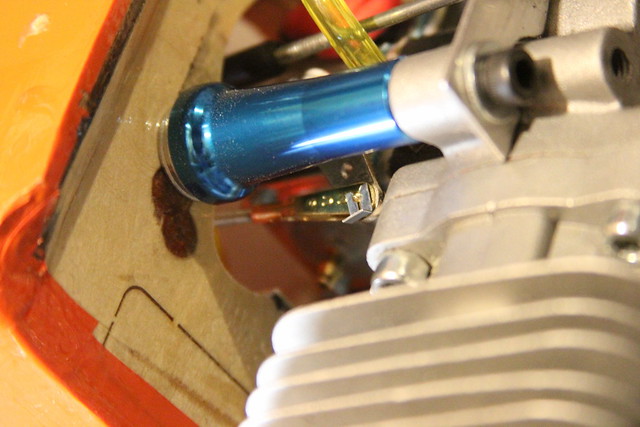
In the meantime, the choke is rigged. It will be accessible through the front of the cowl as with the DA 50 on my 29cc SBach.
Next steps: Round off the corners on the bracket and enlarge the pass-through hole to accept a grommet.
In the meantime, the choke is rigged. It will be accessible through the front of the cowl as with the DA 50 on my 29cc SBach.
Next steps: Round off the corners on the bracket and enlarge the pass-through hole to accept a grommet.
10-15-2013, 06:08 PM
#6
Senior Member
Thread Starter
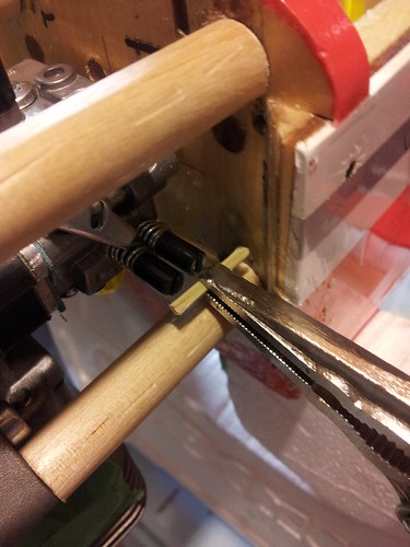
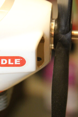
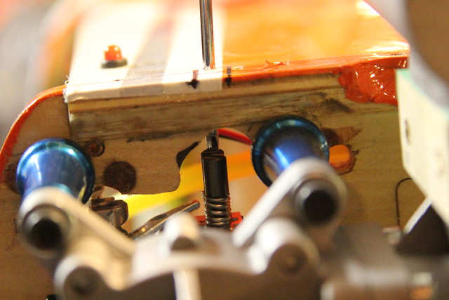
I've rerouted the choke rod to make a straighter run.
Made sure it clears the throttle arm
Put a bend in the end and it clears the prop open or closed.
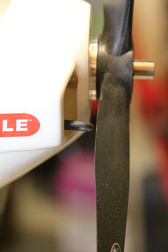
Had to relocate the throttle servo too. I don't think it'll see too much torque so the open servo bay on the other side doesn't concern me.
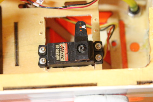
Made sure it clears the throttle arm
Put a bend in the end and it clears the prop open or closed.
Had to relocate the throttle servo too. I don't think it'll see too much torque so the open servo bay on the other side doesn't concern me.


 10-17-2013, 05:15 AM
#8
Senior Member
Thread Starter
Yes indeed - all in good time.
My original plan was to modify this cowl to fit on the Hobbistar that the DLE is going into. That changed when I couldn't find a new cowl for the RCGF 32 - with the plane discontinued, parts are scarce and some are impossible to get for love or money.
So I will be fabbing a custom cowl for the Hobbistar, and this one will stay with the Pulse - decals removed before the maiden!
10-27-2013, 05:05 PM
#9
Senior Member
Thread Starter
You may remember my ruh-roh moment when I tried to attach the muffler to the mounted engine....
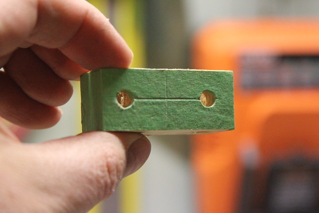
Tonight I mocked up a wooden muffler spacer to see how it would fit - I hope to machine the aluminum one next Sunday.
I made a block 20mm thick, drilled the holes and covered it with tape to keep things clean.
Got the muffler mounted to the engine, the engine mounted to the airframe and the cowl installed.
The spacing is good. And the muffler is not discreet - but I like it.
10-31-2013, 05:40 PM
#10
Senior Member
Thread Starter
ANYway,
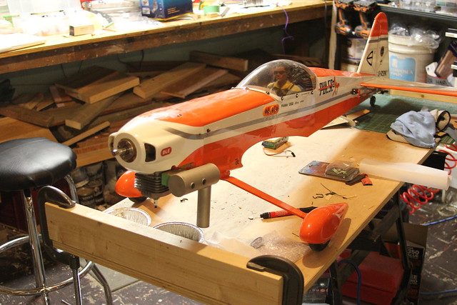
Time to check CG. I fabricated a muffler spacer...
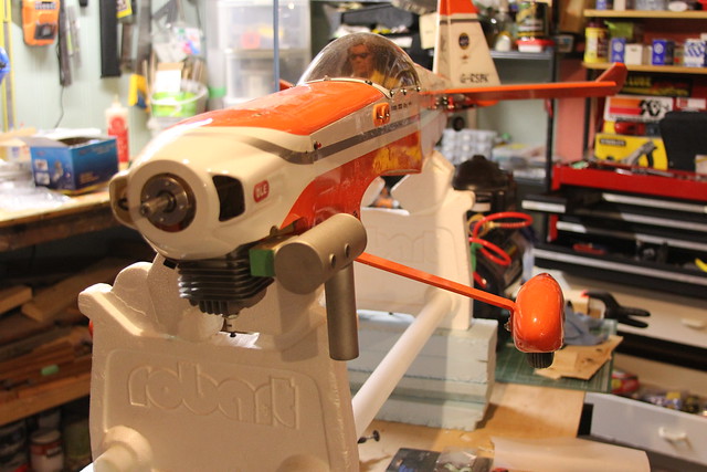
put on the prop and spinner (temporarily)...
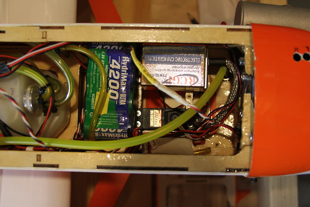
And added the ignition and its battery (also temporarily placed). CG was checked with the scales as usual and after a little futzing around... perfect balance.
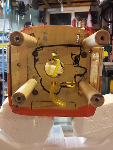
Here's how the battery and ignition will be positioned.
Next up - throttle linkage. Then off to my Uncle's on Sunday afternoon to bore out the 12mm socket and fab the aluminum muffler spacer.
Time to check CG. I fabricated a muffler spacer...
put on the prop and spinner (temporarily)...
And added the ignition and its battery (also temporarily placed). CG was checked with the scales as usual and after a little futzing around... perfect balance.
Here's how the battery and ignition will be positioned.
Next up - throttle linkage. Then off to my Uncle's on Sunday afternoon to bore out the 12mm socket and fab the aluminum muffler spacer.
11-01-2013, 06:30 PM
#11
Senior Member
Thread Starter
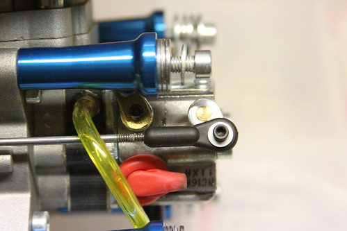
More progress tonight. I got the throttle connected and the end points set.
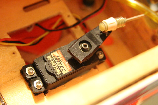
I originally had the ball link on the throttle arm and the gold-n-clevis on the servo arm but I had to swap them due to clearance issues.
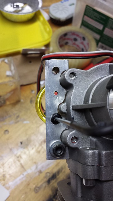
I also got the high and low speed needle access ports done.
High speed:
Low speed:
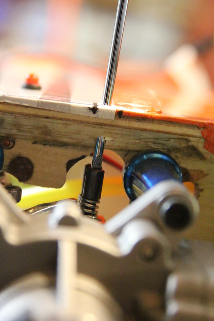
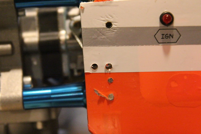
From the outside. The cowl covers that area when it's on so I'll have to pierce it too:
I originally had the ball link on the throttle arm and the gold-n-clevis on the servo arm but I had to swap them due to clearance issues.
I also got the high and low speed needle access ports done.
High speed:
Low speed:
From the outside. The cowl covers that area when it's on so I'll have to pierce it too:
11-01-2013, 08:28 PM
#12


Looking good grosbeak... I have been meaning to ask. I noticed that you used the 3 bladed prop on the DLE as well. Is that because of the landing gear on the Pulse and what size is it?
11-02-2013, 05:42 AM
#13
Senior Member
Thread Starter
The one on the DLE 20 is a 15 x 7; it replaces the 16 x 8 2-blade prop I was using before.
My reasons for a 3-blade:
- Ground clearance
- Braking effect
- I really, really like the way it looks

Last edited by grosbeak; 11-02-2013 at 05:45 AM.
11-05-2013, 03:47 AM
#14
Senior Member
Thread Starter
Getting started on the muffler spacer took a few tries. Initially we worked off the diagram I made but it turns out it's not accurate enough. I needed a way to make an imprint of the flange on the muffler and last night I tried something new.
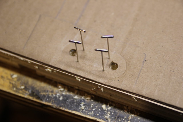
I clamped the muffler to a piece of cardboard...
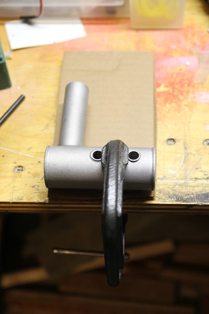
While clamped I drilled the bolt holes through the cardboard using the muffler as a guide. The result was a usable imprint.
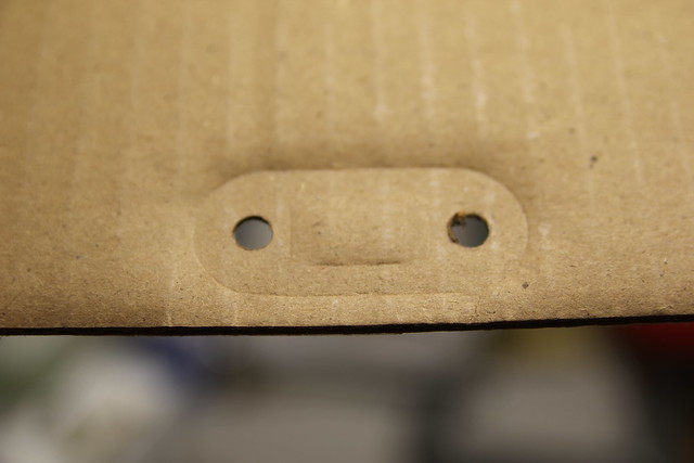
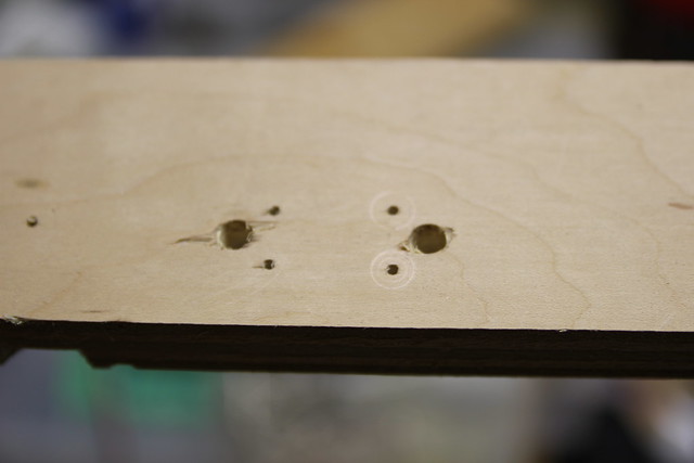
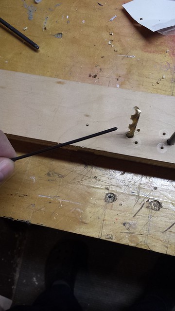
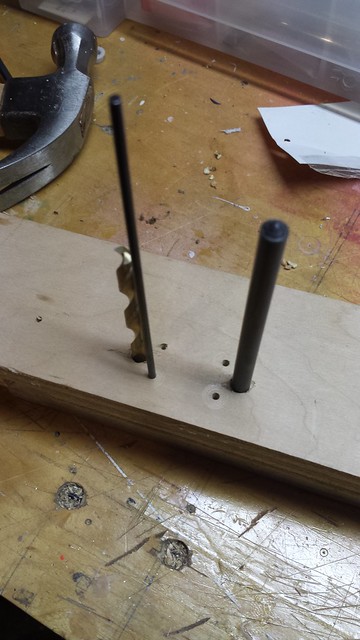
Next step was to pin the template onto a piece of plywood - I pinned by the outer corners of the centre bore and drilled the bolt holes.
Then off came the pins and the cardboard so I could drill the centre bore corners.
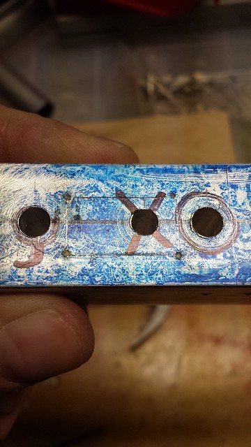
I marked a centre line on the remaining section of aluminum square stock...
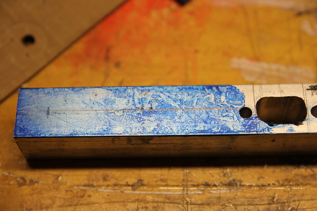
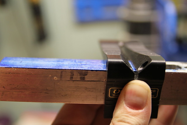
... then used a transfer punch to mark the bolt holes on the side of the aluminum and transferred them to the top with a saddle square.
Marked and punched the bolt holes.
Then to the drill press. Success! I could bolt it onto the engine.
Next step - the centre bore. Then I'll cut the piece off of the square stock and machine it to thickness.
I clamped the muffler to a piece of cardboard...
While clamped I drilled the bolt holes through the cardboard using the muffler as a guide. The result was a usable imprint.
Next step was to pin the template onto a piece of plywood - I pinned by the outer corners of the centre bore and drilled the bolt holes.
Then off came the pins and the cardboard so I could drill the centre bore corners.
I marked a centre line on the remaining section of aluminum square stock...
... then used a transfer punch to mark the bolt holes on the side of the aluminum and transferred them to the top with a saddle square.
Marked and punched the bolt holes.
Then to the drill press. Success! I could bolt it onto the engine.
Next step - the centre bore. Then I'll cut the piece off of the square stock and machine it to thickness.
11-05-2013, 07:05 PM
#15
Senior Member
Thread Starter
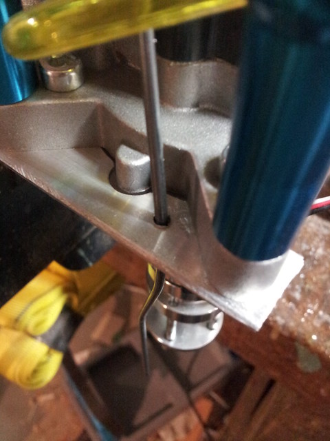
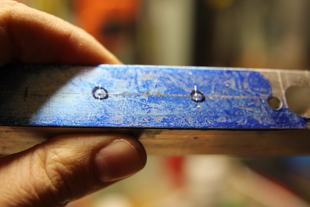
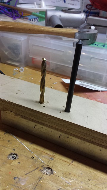
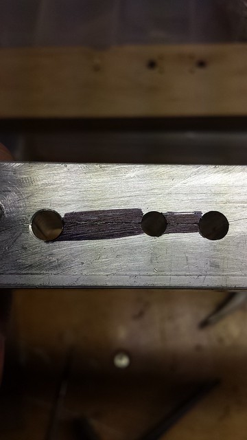
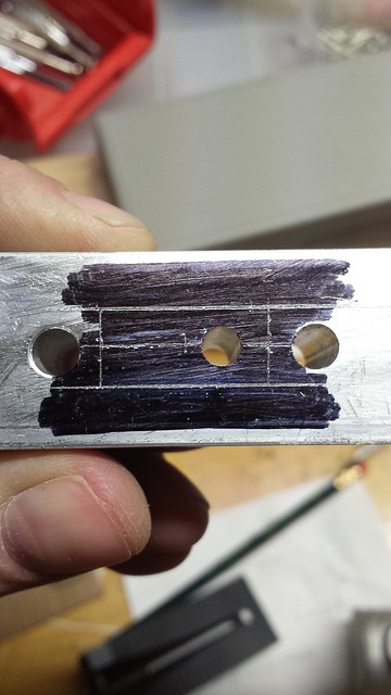
I didn't have a lot of time tonight, but I did get the centre bore marked. I started by pinning my wooden template to the aluminum bar with a 15/64" transfer punch and a 15/64" drill bit. That held it on and kept it from wiggling.
Next step was to mark the corners of the centre bore using a 3/32" transfer punch.
With all four corners marked I used a saddle square to mark the vertical lines and a marking gauge to mark the horizontal lines. As you can see, the outline is not centred on the horizontal reference line.
That's a no-no... so I flipped the bar over and started fresh with a new centre line.
Time for some workshop math.
With the help of metric calipers I got the outline transferred (ignore the centre hole - that's from a previous mistake and inside the centre bore, so it doesn't matter).
11-08-2013, 05:15 PM
#16
Senior Member
Thread Starter
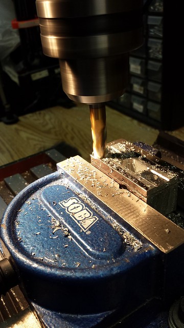
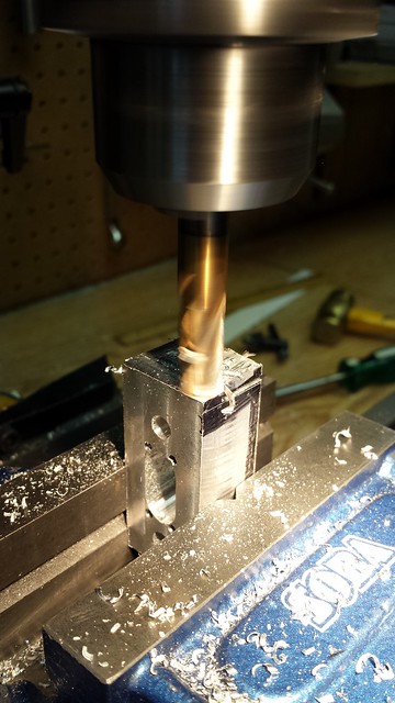
I spent some more time working with my Uncle today. After lots of time on the mill, we got the muffler spacer finished.
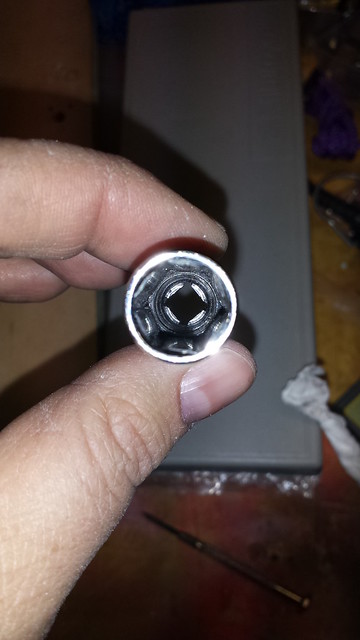
And I left the socket with him last time at his request, and he bored it out.
And I left the socket with him last time at his request, and he bored it out.
11-10-2013, 05:10 PM
#17
Senior Member
Thread Starter
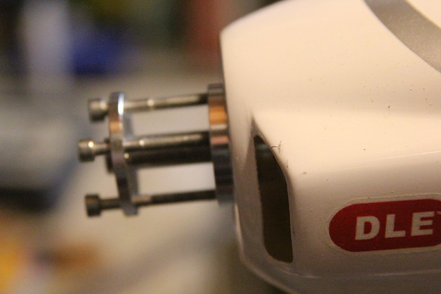
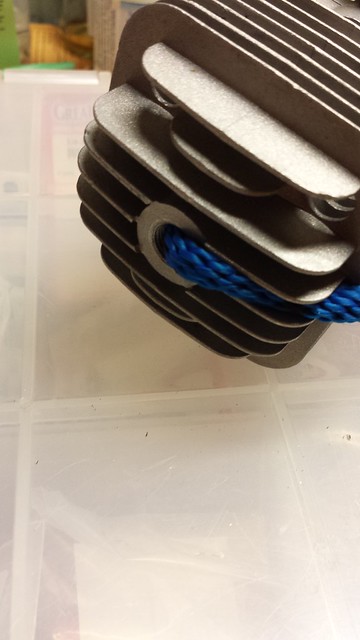
Time to put on the prop adapter. Per Valley View's instructions the first step is to rotate the crank counter-clockwise - the same direction the prop travels - until the piston fully blocks the exhaust port on the upstroke. Then several inches of rope are fed into the spark plug hole.
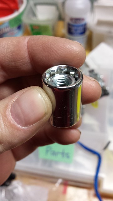
Put the socket on the ratchet and get a firm grip on the engine. It's tight.
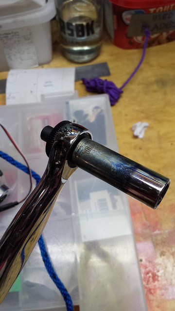
The prop adapter will come out.
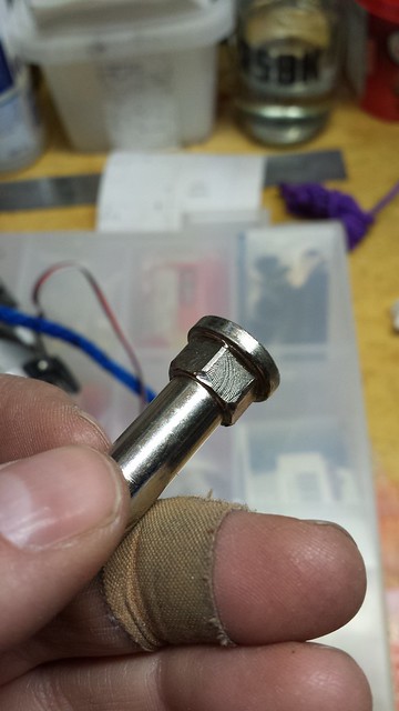
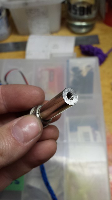
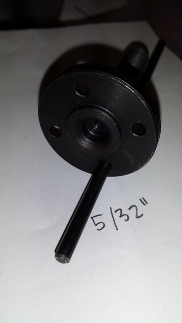
Next step is to cut the prop shaft about 1/16" into the hex nut. I asked Valley View why they didn't just recommend a regular nut, and they replied that the outer dimensions of a standard nut are too big.
I wanted to find out for myself so I checked the thread pitch of the prop shaft - M8 x 1.00 (Metric fine).
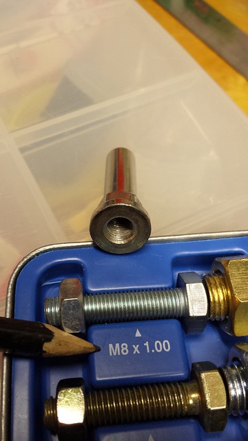
I popped down to my local Home Hardware and picked up several M8 x 1.00 nuts. Tried 'em out at home and sure enough they require a 13mm socket.
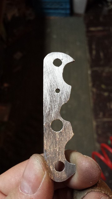
There's no way that socket is going to fit in the hub, so I am going to try removing some excess the outer dimensions of a nut. Seems simple enough to reduce a 13mm span to 12mm... here's the approach I'm going to try.
There's another ruh roh, though.
The valley view prop adapter is for a DLE 30. And even though I very carefully measured the bolt pattern on the RCGF 32, they don't.... quite... match. I tried rotating the adapter to different positions - no joy.
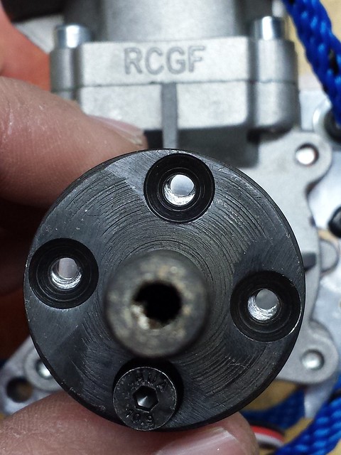
At first, I thought, I would drill out the holes on the prop adapter to the next size. The holes are 5/32".
That's not going to work, though. The bolts from the prop adapter are flat headed, which means they have tapered shoulders that match the countersunk holes in the prop adapter itself. If the bolts don't go into the centre of the holes, the bolt will contact the shoulder of the countersink before it reaches the bottom, and that would put a LOT of stress on the bolt.
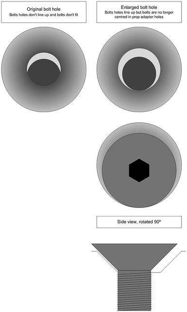
If I want to use this prop adapter only two possible solutions come to mind: Drill and tap new holes in the drive hub to match the prop adapter, or drill and countersink new holes in the prop adapter to match the hub. The former is beyond what I'm willing to do to a perfectly good engine to get a three-blade prop to fit; either would be incredibly difficult to do accurately enough to avoid introducing vibration into the engine. So the prop adapter is out.
I may have to rethink my ideas of a 3-blade prop on this engine... or at least a cheap 3-blade prop. A carbon prop might work if I can get one small enough.
I'm going to let this ruminate for a while. In the meantime, constructive thoughts and suggestions are welcome.
Put the socket on the ratchet and get a firm grip on the engine. It's tight.
The prop adapter will come out.
Next step is to cut the prop shaft about 1/16" into the hex nut. I asked Valley View why they didn't just recommend a regular nut, and they replied that the outer dimensions of a standard nut are too big.
I wanted to find out for myself so I checked the thread pitch of the prop shaft - M8 x 1.00 (Metric fine).
I popped down to my local Home Hardware and picked up several M8 x 1.00 nuts. Tried 'em out at home and sure enough they require a 13mm socket.
There's no way that socket is going to fit in the hub, so I am going to try removing some excess the outer dimensions of a nut. Seems simple enough to reduce a 13mm span to 12mm... here's the approach I'm going to try.
- Mark all sides from 1 to 6
- Carefully grind side 1 until the span is 12.5 mm
- Repeat for sides 2 and 3
- Carefully grind side 4 until the span is 12.0 mm
- Repeat for sides 5 and 6
There's another ruh roh, though.
The valley view prop adapter is for a DLE 30. And even though I very carefully measured the bolt pattern on the RCGF 32, they don't.... quite... match. I tried rotating the adapter to different positions - no joy.
At first, I thought, I would drill out the holes on the prop adapter to the next size. The holes are 5/32".
That's not going to work, though. The bolts from the prop adapter are flat headed, which means they have tapered shoulders that match the countersunk holes in the prop adapter itself. If the bolts don't go into the centre of the holes, the bolt will contact the shoulder of the countersink before it reaches the bottom, and that would put a LOT of stress on the bolt.
If I want to use this prop adapter only two possible solutions come to mind: Drill and tap new holes in the drive hub to match the prop adapter, or drill and countersink new holes in the prop adapter to match the hub. The former is beyond what I'm willing to do to a perfectly good engine to get a three-blade prop to fit; either would be incredibly difficult to do accurately enough to avoid introducing vibration into the engine. So the prop adapter is out.
I may have to rethink my ideas of a 3-blade prop on this engine... or at least a cheap 3-blade prop. A carbon prop might work if I can get one small enough.
I'm going to let this ruminate for a while. In the meantime, constructive thoughts and suggestions are welcome.
11-11-2013, 01:31 PM
#18
Senior Member
Thread Starter
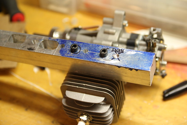
Spent some time in the shop today. I thought I might have to remove more aluminum from the centre bore on the muffler spacer - I put the gasket on and traced around the inside. Sure enough...

I clamped it in the vise and got a file.
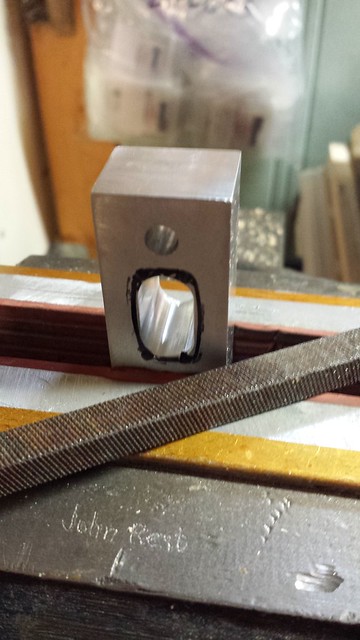
In short order the corner holes were opened up.
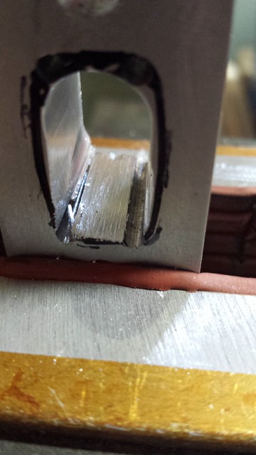
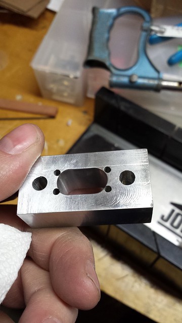
Getting the rest done took a little longer but here it is, a good match to the gasket.
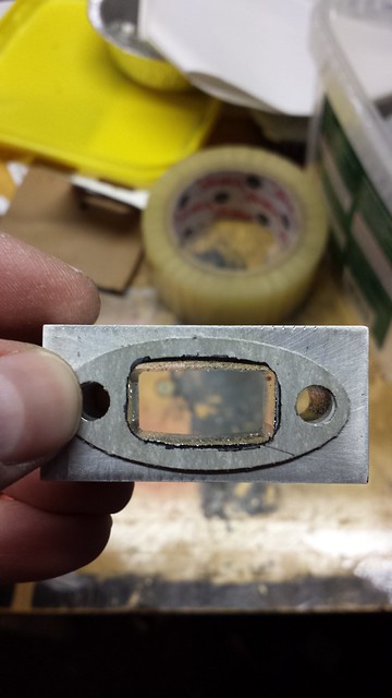
Here's how the block looks now.
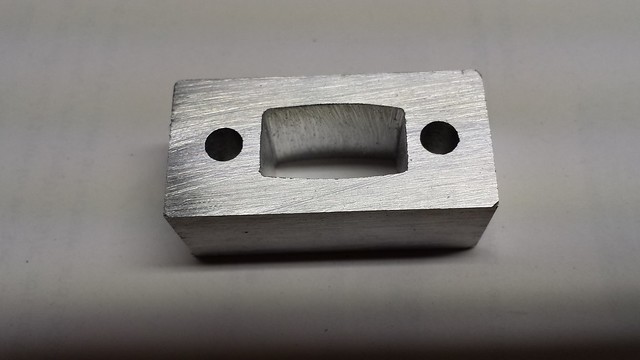
Here it is mounted. I'm very pleased with how this turned out.
Since I was working with metal anyway, I decided to tidy up the choke bracket. Before:
Polished and corners rounded:
Reinstalled:
I clamped it in the vise and got a file.
In short order the corner holes were opened up.
Getting the rest done took a little longer but here it is, a good match to the gasket.
Here's how the block looks now.
Here it is mounted. I'm very pleased with how this turned out.
Since I was working with metal anyway, I decided to tidy up the choke bracket. Before:
Polished and corners rounded:
Reinstalled:
11-17-2013, 02:04 PM
#20
Senior Member
Thread Starter
Heh heh...
Got a bit more done today...
First off, one of the cowl bolts is behind the muffler in a hard-to-reach place. I have some rare earth ring magnets, so I thought I'd use one of those.
Step 1 - Insert the bolt. Blue thread lock.

Step 2 - Cut off the bolt head. I always wear a full face shield with a rotary tool and cutting disk ever since one broke at 50,000 RPM and doinked me in the forehead.


Step 3 - Try it out. Works well.

Step 4: Cut a slot in the cowl bolt hole so it can slide onto the post when the muffler is in place.

Secondly, I got the engine on the plane with the real muffler spacer. I like it!
Step 1 - Bolt it on and put the cowl on.

Step 2 - Tape the spacer in place. The gasket is between the engine and the spacer.

Step 3 - Slide the Nord-Lock washers onto the bolts.

Step 4 - Lay down a thin bead of Permatex Ultra Copper on the muffler spacer where it will contact the muffler.

Step 4 - Make the bolts finger tight (hard to do when they're recessed so far into the muffler, so I just tightened them to the point where the Ultra Copper squeezed out). Leave it for an hour, then tighten it fully.

Thirdly, I made the access holes in the cowl for the Low and High carb needles.
Step 1 - Having located where the holes had to go, I measured the outer diameter of the grommet collar.

Step 2 - Drill out the holes in the cowl to match

Step 3 - The cowl is pretty flush with the fuse so I only wanted the grommets on the outside. A razor blade works well.

Slice one face off, leaving the collar on the other piece.

Step 4 - Test fit the grommets and mark the holes


Step 5 - Glue the grommets in place.


The last thing I did today was to cover up the old carb needle access holes from the DLE 20.

Got a bit more done today...
First off, one of the cowl bolts is behind the muffler in a hard-to-reach place. I have some rare earth ring magnets, so I thought I'd use one of those.
Step 1 - Insert the bolt. Blue thread lock.
Step 2 - Cut off the bolt head. I always wear a full face shield with a rotary tool and cutting disk ever since one broke at 50,000 RPM and doinked me in the forehead.
Step 3 - Try it out. Works well.
Step 4: Cut a slot in the cowl bolt hole so it can slide onto the post when the muffler is in place.
Secondly, I got the engine on the plane with the real muffler spacer. I like it!
Step 1 - Bolt it on and put the cowl on.
Step 2 - Tape the spacer in place. The gasket is between the engine and the spacer.
Step 3 - Slide the Nord-Lock washers onto the bolts.
Step 4 - Lay down a thin bead of Permatex Ultra Copper on the muffler spacer where it will contact the muffler.
Step 4 - Make the bolts finger tight (hard to do when they're recessed so far into the muffler, so I just tightened them to the point where the Ultra Copper squeezed out). Leave it for an hour, then tighten it fully.
Thirdly, I made the access holes in the cowl for the Low and High carb needles.
Step 1 - Having located where the holes had to go, I measured the outer diameter of the grommet collar.
Step 2 - Drill out the holes in the cowl to match
Step 3 - The cowl is pretty flush with the fuse so I only wanted the grommets on the outside. A razor blade works well.
Slice one face off, leaving the collar on the other piece.
Step 4 - Test fit the grommets and mark the holes
Step 5 - Glue the grommets in place.
The last thing I did today was to cover up the old carb needle access holes from the DLE 20.
Last edited by grosbeak; 11-17-2013 at 02:14 PM.
11-17-2013, 03:30 PM
#22
From Step 1, it looks like you are also going to be making a gear change as well. The plug on the RCGF looks as if it will be dragging on the ground. Your going to rip the wings off with the new motor, it's a lot of work and looks great.
On another subject, I am still working on my Pulse 125, and will post some pics on my pilot size thread. I am planning to go with one battery (LiFe A123) and optical kill switch BEC combo.
On another subject, I am still working on my Pulse 125, and will post some pics on my pilot size thread. I am planning to go with one battery (LiFe A123) and optical kill switch BEC combo.
11-22-2013, 01:14 PM
#23
Senior Member
Thread Starter
From Step 1, it looks like you are also going to be making a gear change as well. The plug on the RCGF looks as if it will be dragging on the ground. Your going to rip the wings off with the new motor, it's a lot of work and looks great.
On another subject, I am still working on my Pulse 125, and will post some pics on my pilot size thread. I am planning to go with one battery (LiFe A123) and optical kill switch BEC combo.
On another subject, I am still working on my Pulse 125, and will post some pics on my pilot size thread. I am planning to go with one battery (LiFe A123) and optical kill switch BEC combo.
Should be a good performer. Thanks for the props. No pun intended.
11-22-2013, 01:15 PM
#24
Senior Member
Thread Starter
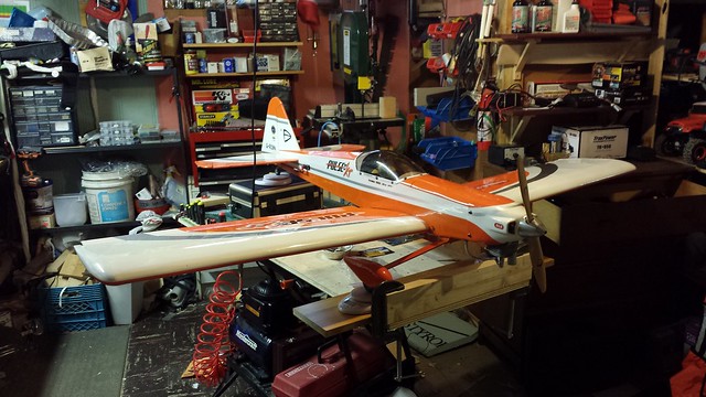
With almost everything done, it was time to double check the balance and mount the ignition components.
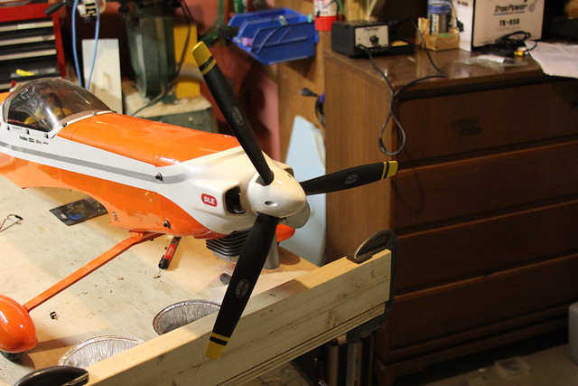
I will be putting a 3-blade 17 x 10 Biela prop on this engine with an aluminum spinner. For balancing I mounted one of the 2-blade 16 x 8 Xoar props I had as extras for my DLE 20. I figured the weights would be pretty close with either prop but I will check them again before the (re-)maiden.
When I was marking my old aluminum spinner for drilling the bolt holes I noticed something that speaks to the lack of quality in this engine: The bolt holes are not equidistant from the prop shaft hole!
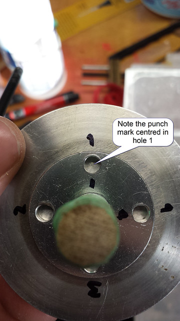
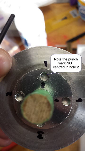
There looks to be about a millimetre difference; it's not as obvious in the photos but it's very clear to the eye. I will be careful drilling props and spinners in future.
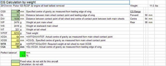
Anyway, I got the prop mounted, all the ignition components loosely placed and the hatch and wings on, the I put the plane on the scales.
By shifting the battery and ignition around I got within a millimetre of the CG. Here's the data from the spreadsheet (click to enlarge):
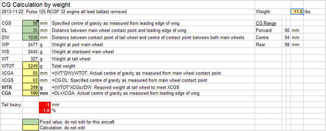
The lateral balance is good with only 30g extra at the port wheel. Nothing to worry about there.
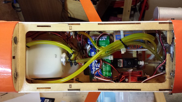
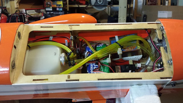
With everything in place, I got all the ignition components mounted and wired up. A place for everything and everything in its place.
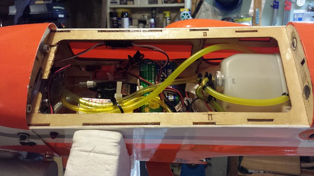
Not much left to do - Install the new prop and spinner (when they arrive), connect the fuel line, put some thread lock on the standoff bolts and charge the batteries. Then mix up some gas and fire it up!
I will be putting a 3-blade 17 x 10 Biela prop on this engine with an aluminum spinner. For balancing I mounted one of the 2-blade 16 x 8 Xoar props I had as extras for my DLE 20. I figured the weights would be pretty close with either prop but I will check them again before the (re-)maiden.
When I was marking my old aluminum spinner for drilling the bolt holes I noticed something that speaks to the lack of quality in this engine: The bolt holes are not equidistant from the prop shaft hole!
There looks to be about a millimetre difference; it's not as obvious in the photos but it's very clear to the eye. I will be careful drilling props and spinners in future.
Anyway, I got the prop mounted, all the ignition components loosely placed and the hatch and wings on, the I put the plane on the scales.
By shifting the battery and ignition around I got within a millimetre of the CG. Here's the data from the spreadsheet (click to enlarge):
The lateral balance is good with only 30g extra at the port wheel. Nothing to worry about there.
With everything in place, I got all the ignition components mounted and wired up. A place for everything and everything in its place.
Not much left to do - Install the new prop and spinner (when they arrive), connect the fuel line, put some thread lock on the standoff bolts and charge the batteries. Then mix up some gas and fire it up!